lancer 1500 Operation Manual
Hide thumbs
Also See for 1500:
- Installation and service manual (20 pages) ,
- Instructions for trouble shooting (2 pages)
Table of Contents
Advertisement
Quick Links
1500/2500 Chiller
Operation Manual
Model 1500
Model 2500
®
Lancer
is a registered trademark of Lancer Corp.
®
For more Information visit
lancerworldwide.com
or call Tech Support/Warranty: 800-729-1550
6655 Lancer Boulevard • San Antonio, TX 78219 • custserv@lancerworldwide.com • ©2023 Lancer Corp. • Lancer PN: 28-3163 • Rev 00-0, 04/17/23
Advertisement
Table of Contents

Subscribe to Our Youtube Channel
Related Manuals for lancer 1500


Summary of Contents for lancer 1500
- Page 1 Lancer Corp. ® For more Information visit lancerworldwide.com or call Tech Support/Warranty: 800-729-1550 6655 Lancer Boulevard • San Antonio, TX 78219 • custserv@lancerworldwide.com • ©2023 Lancer Corp. • Lancer PN: 28-3163 • Rev 00-0, 04/17/23...
-
Page 2: Table Of Contents
TABLE OF CONTENTS ABOUT THIS MANUAL BEFORE GETTING STARTED This booklet is an integral and essential part of the product and Each unit is tested under operating conditions and is thoroughly should be handed over to the operator after the installation for fu- inspected before shipment. -
Page 3: Intended Use
! Intended Use F Electrical Warning • The chiller is for indoor use only and must be installed and ser- • Follow all local electrical codes when making connections. viced by a professional. • Check the chiller nameplate label, located behind the splash •... -
Page 4: Pre-Installation
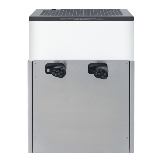
SPECIFICATIONS AND FEATURES 1500 Specifications 26 in 650 mm 19 in 19 in 477 mm 486 mm A. Bonnet B. Water and Syrup Inlets & Outlets C. Front Plate DIMENSIONS WATER SUPPLY Width: 19 inches (486 mm) Min Inlet Pressure: 25 psi (0.172 MPa) Depth: 19 inches (477 mm) Max Static Pressure: 70 psi (0.483 MPA) - Page 5 2500 Specifications 31 in 777 mm 22 in A. Bonnet 553 mm 26 in B. Water and Syrup Inlets & Outlets 659 mm C. Front Plate DIMENSIONS WATER SUPPLY Width: 26 inches (659 mm) Min Inlet Pressure: 25 psi (0.172 MPa) Depth: 22 inches (553 mm) Max Static Pressure: 70 psi (0.483 MPA) Height: 31 inches (777 mm)
-
Page 6: General System Overview
Oetiker Clamp Fittings BAG-IN-BOX (BIB) SYSTEM: Can the countertop support the Water Booster weight of the chiller? BIB Rack (Lancer PN: MC-163172) Is chiller located away from BIB Syrup Boxes Water Regulator (recommended) direct sunlight or overhead lighting? BIB Regulator Set... -
Page 7: Installation
Please read this manual before installation and operation of this unit. Please see pages 10-12 for troubleshooting or service assistance. If this does not resolve the issue and you need additional assistance, please call your Service Agent or Lancer Customer Service. Always have your model and serial number avail- able when you call. -
Page 8: Chiller Installation
300 ppm or 468 µS/cm could cause the lines to freeze. The necessary TDS may be achieved using tap water; however, Lancer recommends using a mixture of 1 tbsp of baking soda for every 5 gals. (19 L) of distilled water. Carefully pour water into the water bath tank until water A. -
Page 9: Cleaning And Sanitizing
General Information GENERAL INFORMATION Lancer equipment (new or reconditioned) is shipped from the factory cleaned and sanitized in accordance with Na- tional Sanitation Foundation (NSF) guidelines. The operator of the equipment must provide continuous maintenance as required by this manual and/or state and local health department guidelines to ensure proper operation and sanitation requirements are maintained. -
Page 10: Maintenance
MAINTENANCE Scheduled Maintenance As Needed • Keep exterior surfaces of chiller clean using a clean, damp cloth. • With a clean cloth and warm water, wipe off all of the unit’s exterior surfaces. DO NOT USE Daily ABRASIVE SOAPS OR STRONG DETERGENTS. Weekly •... - Page 11 TROUBLE CAUSE REMEDY Compressor starts and PCB malfunctioning or faulty ice bank Have the unit repaired by a qualified continues to run until freeze probe. service technician. and will not cut off. Ice bank probe positioned improperly. Check positioning of ice bank probe and replace if needed.
- Page 12 TROUBLE CAUSE REMEDY Compressor does not start (no Compressor relay capacitors or overload Replace compressor relay capacitors or hum), but gas cooler fan motor malfunctioning. overload. runs. Inadequate voltage. Measure voltage across common and run terminal on compressor. Voltage must not Incorrect wiring.
-
Page 13: Illustrations And Part Listings
ILLUSTRATIONS AND PART LISTINGS 1500 Cabinet Assembly Item Part No. Description 82-1207 CAB ASSY,LWR,1500E,CHILLER 30-5535 FRONT PLATE,1500E CHILLER 23-0760/01 CAGE ASSY,LG1500Y,6&1&1 82-2668/01 DCK ASY,RF,1/3,115/60,EIBC,NT 23-1776 BONNET ASSY,SS,1500... - Page 14 2500 Cabinet Assembly Item Part No. Description 82-0820 CAB ASSY,LWR,2500,CHILLER 82-2670 DCK ASY,RF,3/4,115/60,EIBC,NT 23-0650 BONNET ASSY,2500Y,SST 23-0798/01 CAGE ASSY,2500 REF,6&2&1 30-5218 FRONT PLATE,2500 REF...
-
Page 15: Wiring Diagrams
Wiring Diagrams Model 1500 OVERLOAD GREEN BLACK KILL WHITE SWITCH MOTOR AGITATOR MOTOR LANCER BANK CONTROL RELAY PROBE Model 2500 IMPORTANT WHEN STARTING UNIT OR IF CURRENT IS INTERRUPTED, THERE IS A FIVE (5) MINUTE DELAY BEFORE THE COMPRESSOR/FAN STARTS. -
Page 16: Plumbing Diagrams
Plumbing Diagrams Model 1500 - 23-0910 Cage Assembly, 4 Circuit 1500 Chiller, 4 Circuit S1 S2 S3 S4 S3 S2 S1 Model 1500 - 23-0760 Cage Assembly, 6 Circuit 1500 Chiller, 6 Circuit CW PW S1 S2 S3 S4 S5 S6... - Page 17 Plumbing Diagrams Model 2500 - 23-0919 Cage Assembly, 4 Circuit 2500 Chiller, 4 Circuit S1 S2 S3 S4 S3 S2 S1 Model 2500 - 23-1359 Cage Assembly, 6 Circuit 2500 Chiller, 6 Circuit S1 S2 S3 S4 S5 S6 S6 S5 S4 S3 S2 S1 Model 2500 - 23-0798 Cage Assembly, 9 Circuit 2500 Chiller, 9 Circuit...
- Page 18 6655 Lancer Boulevard San Antonio, TX 78219 lancerworldwide.com A HOSHIZAKI COMPANY...
Need help?
Do you have a question about the 1500 and is the answer not in the manual?
Questions and answers