Advertisement
INSTRUCTIONS FOR TROUBLE SHOOTING
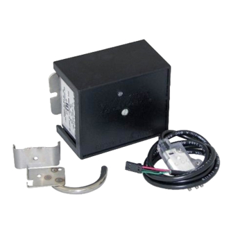
LANCER ELECTRONIC ICE BANK CONTROL (EIBC)
1. To check for normal PCB operation, please refer to the following instructions.
1.1
Turn power OFF or ensure that power has been disconnected from dispenser.
1.2
Pull PCB upward, so that it is no longer connected to the terminal block.
Terminal Block HAS AC LINE VOLTAGE AND SHOULD BE COVERED WITH TAPE.
INSERT A SMALL STRIP OF ELECTRICAL TAPE BETWEEN BOARD AND CONNECTOR TO
PREVENT RE-CONNECTION.
TAPE SHOULD COVER BARE ELECTRICAL CONNECTIONS TO PREVENT ELECTRICAL
SHOCK.
1.3
Disconnect both the Ice Bank probe (J2) and the Carbonator probe (J3) (if equipped) connections
from board (see Figure 1 on reverse).
1.4
Use a short copper wire, paper clip, or other means to short the Ice Bank probe terminals (J2) on
the PCB by touching all three (3) pins together.
1.5
Set Ohm test meter to measure continuity.
1.6
Reconnect power or turn dispenser ON. Observe time and check continuity of the PCB edge
connector (see Figure 1 on reverse).
A. The following should be observed:
1. Terminal 3 to 2 (Carbonator): During the first 2.5 to 3.5 minutes, there should be continuity.
After 2.5 to 3.5 minutes, there should be NO continuity.
2. Terminal 3 to 1 (Compressor): During the first 4 to 6 minutes, there should be NO continu-
ity. After 4 to 6 minutes, there should be continuity. Remove wire from J2 connector. There
should be NO continuity from 3 to 1.
3. You should be able to hear the "click" sound of the relay closing when the time delays end.
1.7
Turn electrical power OFF for 15 seconds and then back ON again to reset Carbonator timer. Again,
measure continuity of the PCB edge connector.
A. Terminal 3 to 2: There should be continuity. Use a short copper wire, paper clip, or other means
to short the Carbonator probe terminals (J3) on the PCB by touching all three (3) pins together.
This should be done before the 2.5 to 3.5 minute time limit has elapsed.
continuity again between Terminal 3 to 2. There should be NO continuity.
1.8
If all the above work as noted, then the board is functioning properly. Remove tape and reconnect
board. If any non-conformities are found, the PCB must be replaced (PN 52-0952/01).
• USA -CANADA – 210-310-7250 • LATIN AMERICA – 210-310-7245 • ASIA – 210-310-7242 •
"Lancer" is the registered trademark of Lancer • Copyright — 1998 by Lancer, all rights reserved.
FOR MODELS: DELTA/1500/800
WARNING
6655 LANCER BLVD. • SAN ANTONIO, TEXAS 78219 USA • (210) 310-7000
FAX SALES
• EUROPE – 32-2-755-2399 • PACIFIC – 61-8-8268-1978 •
FAX ENGINEERING: • 210-310-7096
Measure the
DATE: 03/18/98
P.N.:
28-0393
Advertisement
Table of Contents

Subscribe to Our Youtube Channel
Related Manuals for lancer DELTA


Summary of Contents for lancer DELTA
- Page 1 • USA -CANADA – 210-310-7250 • LATIN AMERICA – 210-310-7245 • ASIA – 210-310-7242 • • EUROPE – 32-2-755-2399 • PACIFIC – 61-8-8268-1978 • DATE: 03/18/98 FAX ENGINEERING: • 210-310-7096 P.N.: 28-0393 "Lancer" is the registered trademark of Lancer • Copyright — 1998 by Lancer, all rights reserved.
- Page 2 SHORT OUT PINS ICE BANK PROBE TERMINAL CARBONATOR PROBE TERMINAL 24VAC CARB COMP RELAY RELAY PCB EDGE CONNECTOR TAPE TERMINAL BLOCK Figure 1 Check out the Lancer web site: www.lancercorp.com...
Need help?
Do you have a question about the DELTA and is the answer not in the manual?
Questions and answers