
Related Manuals for Diesse VES-MATIC 20


Summary of Contents for Diesse VES-MATIC 20
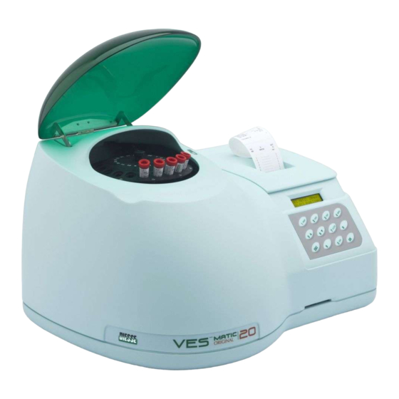
- Page 1 DIESSE DIAGNOSTICA SENESE S.P.A. VES-MATIC 20 VES-MATIC 20 PLUS Service Manual Release 1.00 - English Automatic instrument for the determination of the erythrosedimentation rate (ESR) (patent pending)
- Page 2 The information contained in this manual can be subject to modification without notice. Any of the parts of this manual can be reproduced in any way or media electronic or mechanical, for any use, without the written authorisation of Diesse Diagnostica Senese S.p.a.
-
Page 3: Table Of Contents
TABLE OF CONTENTS VES MATIC 20 / VES MATIC 20 PLUS INTERVENTION PROCEDURES (TROUBLE SHOOTING) ..........p.5 1.1. Approach to the VES MATIC 20 / VES MATIC 20 PLUS instrument 1.2. Analysis of the faults 1.2.1. The instrument does not switch on 1.2.2. - Page 4 Appendix F: CONNECTION TO A HOST COMPUTER AND SPECIFICATIONS OF THE COMMUNICATIONS PROTOCOL FOR VES-MATIC 20 / VES MATIC 20 PLUS Appendix G: CONNECTION OF A BARCODE READER TO INSTRUMENTS OF THE VES LINE Appendix H: FIRMWARE UPGRADE FOR THE VES MATIC 20 AND VES MATIC 20 PLUS...
-
Page 5: Ves Matic 20 / Ves Matic 20 Plus Intervention Procedures (Trouble Shooting)
VES MATIC 20 / VES MATIC 20 PLUS - INTERVENTION PROCEDURES (TROUBLE SHOOTING) Before performing any type of intervention on the instrument: a) SWITCH OFF THE ON/OFF SWITCH ON THE VES MATIC INSTRUMENT. b) DISCONNECT THE INSTRUMENT FROM THE POWER SUPPLY IN ORDER TO AVOID ANY RISK OF CONTACT WITH ELECTRICAL OR MECHANICAL PARTS UNDER LINE VOLTAGE. -
Page 6: Analysis Of The Faults
1.2. ANALYSIS OF THE FAULTS The faults reported in the following paragraphs make reference to the Trouble Shooting procedures described for the individual modules, in order to demonstrate the type of approach to follow in these situations. 1.2.1. The instrument does not switch on a) Check that the mains power supply is working. -
Page 7: The Instrument Switches On / Printer
1.2.3. The unit is on/display a) The display visualizes but does not illuminate (backlighting ) b) The display does not visualize but illuminate c) The display does not visualize and does not illuminate d) The display visualize but the data can not be entered with the keyboard See Display/Keyboard module procedure (5.3.). - Page 8 EXPLODED VIEW AND PART LIST TABLE...
- Page 9 Espl oso M eccani ca VES-M ATI C 20 N ew - Pag. 1/4...
- Page 10 Espl oso M eccani ca VES-M ATI C 20 N ew - Pag. 2/4...
- Page 14 30002870 – Ves-Matic 20 New Part list 30002570 – Ves-Matic 20 Identisystem 30002830 – Ves-Matic 20 Plus Code Description Note Position 10325860 Case power supply 10128470 Insulator pad for power supply 10301290 Ves20 painted tray 10126400 V20 pivot plate 10327500...
- Page 15 Position Code Description Note 10127270 V20 bubble zipper guide 10325840 Half-case/microswitch support 10127910 V20 glass display 1110F35Z Würth 0683-284-3 (single) self-adhesive buffer 10301330 Ves20 painted up case 10328090 V20 painted box printer 10126750 Paperbreaking 30204720 Assembly fulcrum zipper printer cover 10127260 Printer cover zipper 10301280...
- Page 16 Position Code Description Note 1110010Z STEAB 5021/5////05 spacer 1110675Z Benzing ring 6 UNI 7434-75 11712010 1056 MXL 025 (svil. 268,386) belt 12500290 Zipper art. 101 30x30 nikel. 21200680 Microswitch Honeywell V5C010BG1L PrinterPANAS.EPL-1902S2AE(PAN-MEC000200) 21430120 12300010 Termal printer roll l=58 mm 10326070 Plate microswitch 10125620 Bush of beat...
- Page 17 Position Code Description Note 11141394 Screw M4x10 UNI 5931 inox 1114474L Nut M4 UNI 5588 inox 1114501Z Washer 4,3x9 UNI 6592 inox 1110026Z Hexagonal spacer M-F M3x30 1110027Z Hexagonal spacer M-F M3x10 11141404 Screw M4x12 UNI 5931 inox 11141192 Screw M3x10 UNI 7687 inox 1110021Z Hexagonal spacer M-F M3x15 11141402...
- Page 18 Position Code Description Note 11141172 Screw M3x6 UNI 7687 inox 11141183 Screw M3x8 UNI 7688 inox … … … -------------------- Cables list--------------------------------- Position Code Description Note 30113870 Signals motors driver cable V30/V20 new 30114280 Flash writer cable Ves20 30114270 Seriale cable RS232C V20 30114260 Barcode reading cable ext.
-
Page 19: Procedure To Dismount
PROCEDURE TO DISMOUNT THE ROTATION GROUP-SAMPLE HOLDER PLATE (see figure of exploded views) Proceed step by step as reported below a) Follow the recommendations in paragraph 1 points a) and b) b) Unscrew the 5 screws (pos. 089) on the base’s external sides. c) Open the outer covering (Pos. - Page 20 CALIBRATION PROCEDURE OF THE UNIT VES MATIC 20 /VES MATIC 20 PLUS AFTER THE DISASSEMBLY OR FOR THE PERIODICAL PROTOCOL. When the unit is assemblied back keeping the carter opened: Access to the instrument keeping pressed the button “0” of the keyboard, the instrument pages to automatically in “TEST FACTORY”.
- Page 21 Pressing the button “1” of the keyboard we select the dates trasmission like on the old instruments Ves Matic 20/60 on the display appears: Serial Protocol OLD PROTOCOL Pressing the button “2” of the keyboard we select the new dates trasmission on the display appears: Serial Protocol NEW PROTOCOL...
- Page 22 Pressing the button “ESC” we cancel the set up date and we place the instrument for the insertion of the new date, on the display appears: DATE DD/MM/YEAR Pressing the numerical buttons we insert the day, the month then the last two figures that indicate the year.
- Page 23 Ex. We want to insert the following time 08:50:52 Pressing: For the hours: Button”0” Button “8” For the minutes: Button “5” Button “0” For the seconds: Button“5” Button “2” Pressing the button “OK” we confirm what we have pressed, automatically the instrument updates the time , the date an the printer prints : * * * * * * * * * * * * * * * * * * CLOCK TEST...
- Page 24 TRANSLATOR If there were some faultes the printer prints the following report: * * * * * * * * * * * * * * * * * * TRANSLATOR TEST * * * * * * * * * * * * * * * * * * TRANSLATOR If test “KO”...
- Page 25 sample holder plate rotation and places itself on the new ofset set up. The display shows the new set up value. Pressing the button “ESC” we get out from the procedure and we come back to the menù “TEST FACTORY” -select pressing the button “6”...
- Page 26 Insert the Check Device in the special place, with the arrow put in the direction of the instrument and the white side with Diesse green logotype in up direction. Press a button’s keyboard and on the diplay appears :...
- Page 27 CARD EXAUSTED! 00000 -select pressing the button “9” the voice “BARCODE” on the display appears: VES MATIC 20New COD: With this menù we can verify the barcode working for the instruments in version IDSYSTEM. After the selection the instrument overturns the sample holder plate in a way it can take it in the bar code reading position, pressing the button “5 UP arrow”...
- Page 28 position, at every stop comes made a trolley reset, that brings the reading sensor. This test is useful in assembly and disassembly case of the sample holder group plate for to verify in automatically the right movement. For to finish the test press the button “ESC”.
-
Page 29: Procedures To Follow For Interventions On The Different Modules
PROCEDURES TO FOLLOW FOR INTERVENTIONS ON THE DIFFERENT MODULES 5.1. SERVICE MANUAL THE POWER SUPPLY MODULE (Pos. 072) 5.1.1. General 5.1.1.1. Aim 5.1.1.2. Applicability 5.1.2. Relative documentation 5.1.3. Relative instrumentation 5.1.4. Trouble shooting 5.1.4.1. Description of the module 5.1.5. Flow Chart no. 2 5.1.6. -
Page 30: Relative Documentation
5.1. SERVICE MANUAL THE POWER SUPPLY MODULE (Pos. 072) 5.1.1. General 5.1.1.1. The present document furnishes details of the Trouble Shooting procedures regarding the Power supply module (Pos. 072), assembled on the VES MATIC 20 / VES MATIC 20 PLUS instrument. 5.1.1.2. - Page 31 5.1.5. Flow Chart no. 2 Trouble shoooting phase in relation to the Power Supply module (Pos. 072). Power supply Check Power On Fuse Fuse Change the fuse OK ? Check the supply Cable Change the supply Cable OK ? Cable Change power supply Board...
- Page 32 5.1.6. Access to the module Disconnect the VES MATIC 20 / VES MATIC 20 PLUS instrument from the power supply, as reported in paragraph 1. Remove the outer covering as reported in paragraph 2 in order to gain access to the internal parts.
- Page 33 Appendix A: Examination of the possible faults The examination of the main defects is performed according to the table reported below: Type of failure The voltage is not coming through on connector pos. 209 Local effect The indicator LEDs of CPU board (pos. 048) are off. General effect No voltage is going out to the different connectors.
- Page 34 5.2. SERVICE MANUAL CPU MODULE (Pos. 048) 5.2.1. General 5.2.1.1. Aim 5.2.1.2. Applicability 5.2.2. Relative documentation 5.2.3. Relative instrumentation 5.2.4. Trouble shooting 5.2.4.1. Description of the module 5.2.5. Flow Chart no. 3 5.2.6. Access to the module Appendix B: Examination of the faults...
- Page 35 5.2. SERVICE MANUAL CPU MODULE (Pos. 048) 5.2.1. General 5.2.1.1. Aim The present document reports in detail the Trouble Shooting procedures regarding the CPU unit code 30100020, assembled on the VES MATIC 20 / VES MATIC 20PLUS instrument. 5.2.1.2. Applicability The recommendations reported here below are applicable in the final service check to ascertain acceptability of the product.
- Page 36 a) MPU and CONTROL ADDRESS/DATA BUS Block This block includes the microprocessor which performs the functions according to the resident programme. It contains a system clock of 6 Mhz and a bus speed (speed at which an operation is performed) of 6 Mhz. b) MEMORY Block FlashEprom This is integrated in the CPU processor which contains the control...
- Page 37 5.2.5. Flow Chart no. 3 Il Flow Chart n°3 mostra il diagramma di flusso per quanto riguarda la CPU pos. 048 Control visualization Date on display Effect Calibration Procedure Visualization See point 4.a Control visualization Date on display Raplace CPU Visualization Function of CPU On switching on...
- Page 38 5.2.6. Access to the module a) Disconnect the VES MATIC 20 / VES MATIC 20 PLUS from the power supply, as in paragraph 1. b) Gain access to the inside of the instrument as reported in paragraph 2. c) Losen the screw pos. 051 and remove the case pos. 047 d) Disconnect the cable on CPU board pos.
- Page 39 Appendix B: Examination of the possible faults An examination of the main defects is performed according to the table reported below: Type of failure The timer is not working. Local effect The clock on the display is not updated. General effect The date is not memorized in the instrument.
- Page 40 5.3. SERVICE MANUAL DISPLAY/KEYBOARD MODULE (pos. 064/065) 5.3.1. General 5.3.1.1. Aim 5.3.1.2. Applicability 5.3.2. Relative documentation 5.3.3. Relative instrumentation 5.3.4. Trouble shooting 5.3.4.1. Description of the module 5.3.5. Flow Chart no. 4 5.3.6. Access to the module Appendix C: Examination of the faults.
- Page 41 5.3. SERVICE MANUAL DISPLAY/KEYBOARD MODULE (Pos. 064/065) 5.3.1. General 5.3.1.1. Aim The present document reports details of the Trouble Shooting procedures relating to the Display/Keyboard module pos. 064 and 065 assembled on the VES MATIC 20/VES MATIC 20 PLUS. 5.3.1.2. Applicability The recommendations contained in the present document are applicable to final servicing to ascertain the acceptability of the product.
- Page 42 5.3.5. Flow Chart no. 4 The Flow Chart n° 4 shows the flow chart for the Trouble Shooting part’s form Display/Keyboard pos. 064/065. Diplay Check Display Verify Connection connection CPU OK ? Check Feeding Verify feeding Feeding OK ? Check Display Change Display OK ?
- Page 43 5.3.6. Access to the module a) Turn off the feeding to the VES MATIC 20 / 20 PLUS like paragraph 1. b) Come in to the unit opening the plug like paragraph 2. c) Take off the interface cable connected on the board’s connector CN2 pos. 065. d) Unscrew the crews (pos.
- Page 44 Appendix C: Examination of the possible faults An examination of the main defects is performed according to the table reported below: Type of failure There is no visualization. Local effect The keyboard works and voltage is present in the display; the CPU works.
-
Page 45: Flow Chart No
5.4. SERVICE MANUAL PRINTER INTERFACE MODULE Pos. 066 5.4.1. General 5.4.1.1. Aim 5.4.1.2. Applicability 5.4.2. Relative documentation 5.4.3. Relative instrumentation 5.4.4. Trouble shooting 5.4.4.1. Description of the module 5.4.5. Flow Chart no. 5 5.4.6. Access to the module Appendix D: Examination of the faults. - Page 46 5.4. SERVICE MANUAL PRINTER INTERFACE MODULE (Pos. 066) 5.4.1. General 5.4.1.1. Aim The present document reports in detail the Trouble Shooting procedures to be used in relation to the Printer Interface Module pos. 066, assembled on the VESMATIC 20 / VES MATIC 20 PLUS.
- Page 47 5.4.5. Flow Chart no. 5 Interface module Trouble shooting. Printer Check Paper Paper Insert OK ? Paper Check Paper Insert Paper Paper correctly OK ? Check Power Supply on CN11 Power Replace Power OK ? cable Replace Interface board Printer Check Head lever up Lever...
- Page 48 5.4.6. Access to the module a) Disconnect from the power supply, as in paragraph 1. b) Open the outer covering (pos. 046)to gain access to the inside of the instrument and unscrew the screw pos.160, extract the printer module. c) Disconnect the power supply cable on connector CN11. d) Disconnect the serial cable connected on CN12.
- Page 49 Appendix D: Examination of the faults. An examination of the main defects is performed according to the table reported below: Type of failure The printer does not print. Local effect The paper does not advance forward with the printed results. General effect Printing does not take place.
-
Page 50: Flow Chart No
5.5. SERVICE MANUAL MOTORS AND CONTROLS BOARD pos. 061 5.5.1. General 5.5.1.1. Aim 5.5.1.2. Applicability 5.5.2. Relative documentation 5.5.3. Relative instrumentation 5.5.4. Trouble shooting 5.5.4.1. Description of the module 5.5.5 Flow Chart no. 6 5.5.6. Access to the module Appendix E: Examination of the faults. - Page 51 SERVICE MANUAL MOTOTRS AND CONTROLS BOARD POS. 061 5.5.1 General 5.5.1.1. Aim The present document reports in detail the Trouble Shooting procedures to be used in relation to the Motors and Controllers Board pos. 061, assembled on the VES MATIC 20 / 20 PLUS. 5.5.1.2.
- Page 52 5.5.5 Flow Chart no. 6 Trouble shooting phase in the Motors and Controls Board. Motors and driver Board Motors driver board Error message: ERROR READING Error message: ERROR MIXING Check Replace Breakin belt belt Check Replace Plate Motore Motor Error message: ERROR READING Error message: ERROR MIXING...
- Page 53 Motors driver Board Error message: ERROR PLATE Check Replace Cabled moto Motoreduc. reductor Error message: ERROR PLATE Check Replace Sensor Sensors Plate Replace I/O board 5.5.6. Access to the module a) Disconnect from the power supply, as in paragraph 1. b) Open the outer covering to gain access to the inside, as in paragraph 2.
- Page 54 Appendix E: Examination of the faults. An examination of the main defects is performed according to the table reported below: Type of failure The Self-Test starts up with the error message: ERROR READING. Local effect The data is not read, or is read incorrectly. General effect Error message;...
- Page 55 Appendix F: HOST COMPUTER CONNECTION FOR VES-MATIC LINE INSTRUMENTS AND VES-MATIC 20 / 20 PLUS COMMUNICATION PROTOCOL. Check that the connection cables are 3 wire connectors (Tx-Rx-Gnd) and are connected as follows: VES CONNECTOR HOST-COMPUTER CONNECTOR Type DB9 Type DB9...
- Page 56 SPECIFICATIONS FOR THE ASYNCHRONOUS SERIAL COMMUNICATION PROTOCOL Representation of the bytes transmitted on the serial line: STX BLK BLK LEN LEN ADD ADD COM ETX CHK Each box represents 1 byte transmitted on the serial port. The pair of bytes will instead be packed in the memory and return to the value of 1 byte.
- Page 57 Each command is interpreted and receives as reply ‘ACK’=[0x06]+ID+CR If a syntax error occurs or an incorrect command is issued, the reply will be ‘NACK’=[0x15]+ID+CR 0x01: Request of version Example: From Host >00000181+CR+00 Asks unit with ID ‘01‘ to run command ‘81’ (that is command ‘01’...
- Page 58 ESR settings during the reception 1byte (X X BO BE BI FP FD FT where FT= temperature correction flag 1 is ON, FD=Displayed results flag, FP=Printed results flag, BI=Internal bar code selection flag, BE=External bar code selection flag, BO= Barcode deselection flag) Number of samples 1 byte Cycle 1byte Temperature during test 1 byte...
- Page 59 0x04: Command to request the unit status The unit status is constituted by 2 ASCII hex integers represented by means of two sets, each with 4 bytes. The first four bytes contain the following information: Bit value: Code Test type Test type Test type Reset in progress...
- Page 60 0x05: Reading the Setting register The unit returns the value of the setting register in 2 ASCII hex bytes. The register bit have a Boolean value (1=ON) Code Temperature correction Displayed results Printed results Internal barcode External barcode Disabled barcode Example: From Host Send command >00000185+CR+00...
- Page 61 0x07: Start test The command enables to start and select the type of test. The type is codified as follows: Type Code 0x01 F1 Normal 0x02 F2 Normal 0x03 F1 Kinetic 0x04 F2 Kinetic Example: From Host Sends command >0002018703+CR+00 Ask the unit with ID ‘01‘...
- Page 62 The units sends the 13 character code related to the requested barcode. 0x0A: Write barcode This command enables the write the barcode in the desired position during the test cycle. Positions range from 0 to 19 for VES20. Example: From Host Send command >000F018A07ABCDEFGHILMNO+CR+00 Ask unit with ID ‘01‘...
- Page 63 Example: From Host Send command >000C018C0C00000F0601+CR+00 Ask unit with ID '01' to run command ‘0x8C’ (that is command ‘0x0C’ without checksum control) with data field 0C00001F0601. This enables to set the timer at 12:00:00 hours and with a 15/06/01 date . From ESR ‘ACK’...
- Page 64 CONNECTING A BAR CODE READER TO VES 20/30 INSTRUMENTATION The identification number of the samples (ID) can be entered manually or through the BAR CODE READER. 1. Before performing any connection, check that the presence of the following signals on the connector used for connection purposes (refer to the instruction manual of the bar code reader): EXTERNAL DB9 CONNECTOR...
- Page 65 Appendix H: FIRMWARE UPGRADE FOR THE VES MATIC 30 AND VES MATIC 30 PLUS INSTRUMENT VES20NEW & VES30NEW PROGRAMMING MANUAL Ver. 1.1 - 23.07.01 PROGRAMMING SOFTWARE INSTALLATION Create the folder C:\AVRTOOLS directly on C:\ Copy the file Atmelisp.exe from floppy disk to C:\AVRTOOLS. The file Atmelisp.exe is a compressed file that when started decompress all the files it contains.
- Page 66 Connector for PROGRAMMATION Connect the 9-ways D-sub male connector (Programming Key), included in the Programming Kit, to the female connector ‘RS232’ placed near the programming panel. Insert the mains cable and turn on the Instrument. PROGRAMMING PROCEDURE Start the program ISP.EXE on the Personal Computer. Select ‘Project’...
- Page 67 START PROGRAMMING A. Select ‘Program’, and then ‘Auto-Program Options’. Check on all the available options except ‘Reload files’ and ‘Program Security bits’ that must be de-selected and press OK. B. Press F5 to start programming. C. If during the procedure there are errors the program will inform you, otherwise no message will be displayed.
- Page 68 Appendix I: LAYOUT FOR ELECTRONIC CONTROL BOARD AND SCHEMATICS...
Need help?
Do you have a question about the VES-MATIC 20 and is the answer not in the manual?
Questions and answers