Diesse CUBE 30 TOUCH Service Manual
Automatic instrument for esr determination with modified westergren method, only for in vitro diagnostic use
Hide thumbs
Also See for CUBE 30 TOUCH:
- Service manual (113 pages) ,
- User manual (80 pages) ,
- Quick start manual (3 pages)

Related Manuals for Diesse CUBE 30 TOUCH


Summary of Contents for Diesse CUBE 30 TOUCH
- Page 1 SERVICE MANUAL Rev 1.0 March/2018 SW Rel. 1.xx Automatic instrument for ESR determination with modified Westergren method Only for in vitro diagnostic use 1/66 Rev 1.0 13/03/2018...
- Page 2 MANUAL DESCRIPTION OF MODIFICATION APPR. REVISIONS 03/2018 Official Version MODELS This manual applies to the following CUBE 30 TOUCH model: DIESSE Code Model description CUBE 30 TOUCH 10395 TECHNICAL ASSISTANCE DIESSE DIAGNOSTICA SENESE SpA - CUSTOMER CARE Via del Pozzo 5, 53035 Monteriggioni (SI), Italy Tel.
-
Page 3: Table Of Contents
CONTENTS GENERAL DESCRIPTION OF THE INSTRUMENT ............5 1.1. OVERALL VIEW OF THE UNIT ................6 1.2. TECHNICAL SPECIFICATIONS ................8 1.3. INSTALLATION ...................... 9 1.4. SHUTTING DOWN AND SHIPPING ............... 9 SERVICE MENU ......................11 2.1. SERVICE FUNCTIONS ..................12 2.1.1. - Page 4 ATTACHMENT A: EXTERNAL CONNECTIONS ..............58 GENERAL SPECIFICATIONS FOR CONNECTING TO A BARCODE READER. 59 CONNECTION TO A HOST COMPUTER Rev 1.0 13/03/2018 4/66...
-
Page 5: General Description Of The Instrument
GENERAL DESCRIPTION OF THE INSTRUMENT 1.1. OVERALL VIEW OF THE UNIT ....................6 1.2. TECHNICAL SPECIFICATIONS ....................8 1.3. INSTALLATION .......................... 9 1.4. SHUTTING DOWN AND SHIPPING ................... 9 5/66 Rev 1.0 13/03/2018... -
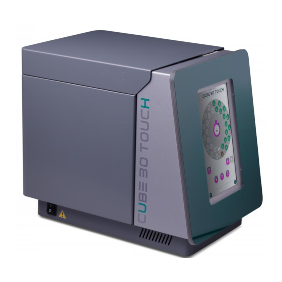
Page 6: Overall View Of The Unit
OVERALL VIEW OF THE UNIT Fig. 1.1 The CUBE 30 TOUCH module consists of a single body containing all the operating functions necessary for analyzing the sample. The instrument has 30 housings arranged in two concentric circles with 15 positions each, which allow the insertion of samples. - Page 7 EXTERNAL CONNECTIONS On the rear side of the instrument, there is a power supply connector. On the left side of the instrument, there is the ON/OFF power button. On the right side of the instrument, there are: two connectors for connection with Computer / HOST. One RS232 Serial type (9pin) and the other USB type.
-
Page 8: Technical Specifications
1.2. TECHNICAL SPECIFICATIONS Internal use Europe: 230Vac@50Hz; POWER SUPPLY Usa/Canada: 110-120Vac@60Hz Power: 100VA DIMENSIONS 297x450x390 (l x p x h) (mm) WEIGHT 14 kg ROOM Operating temperature From +5° to +35°C TEMPERATURE Storage temperature From +5° to +45°C RELATIVE 20%-80% without condensation HUMIDITY (RH) ALTITUDE Maximum 2000 meters (6562 ft) -
Page 9: Installation
1.3. INSTALLATION Please refer to the User Manual for the installation procedure. 1.4. SHUTTING DOWN AND SHIPPING Before shutting down and shipping the instrument it is recommended carrying out the following sanitising procedure: A) The instrument must be turned off and cleaned internally of all residues or spillage with a liquid detergent and left to dry. - Page 10 SHIPPING Put the instrument into its plastics bag and place into its own box as shown in the installation guide. If the instrument is being shipped to the manufacturer for repairs, affix a copy of the “Fault Report” form to the outside of the box. Rev 1.0 13/03/2018 10/66...
-
Page 11: Service Menu
SERVICE MENU 2.1. SERVICE FUNCTIONS ......................12 2.1.1. ACCESS TO THE SERVICE MENU ..................12 2.1.2. SERVICE MENU ........................15 2.1.3. DIAGNOSTICS FUNCTIONS ....................21 2.1.3.1 TOUCH PANEL CALIBRATION ....................22 2.1.3.2 BUZZER TEST ......................... 22 2.1.3.3 EEPROM TEST ........................22 2.1.3.4 SD CARD TEST ........................ -
Page 12: Service Functions
2.1. SERVICE FUNCTIONS 2.1.1. ACCESS TO THE SERVICE MENU Starting up the system PROCEDURE: Turn on the instrument. When the instrument turns on, it shows the following menu: Settings Press the Settings Button to access the Settings Menu. Rev 1.0 13/03/2018 12/66... - Page 13 Press SERVICE to access to the ACCESS CODE Input Page: Service 13/66 Rev 1.0 13/03/2018...
- Page 14 In the Top part of this page you can find the current Firmware Version and its release date. ACCESS CODE LIST: 98521 14785 74159 SERVICE PARAMETERS VIEWER Rev 1.0 13/03/2018 14/66...
-
Page 15: Service Menu
2.1.2. SERVICE MENU Page 1- Function: Function Description Default The instrument's serial number HCT HOST For future uses, always set to OFF HOST BY USBH In USB /Serial link to ves matic Protocol to host: ON = on USBH (USB HOST) with FTDI (USB/Serial Adaptor) OFF = on CDC (USB DEVICE) : direct USB connection to the PC, requires “STM32”... - Page 16 STANDBY > To set the screen save function and the brightness of the CUBE 30 TOUCH written. TIME STANDBY: Time of inactivity, in Seconds, after which the Instrument goes in Stand-by mode. Set = 0 to deactivate the Standy-by management.
- Page 17 ARCHIVES DELETE: Delete all archives LOG DELETE: Delete all log files SD BACKUP: Copy all files to internal CUBE 30 TOUCH in a USB key It is advisable to do this in a completely empty key SD RESTORE: Copy all the files in a USB key in uSD inside the CUBE 30 TOUCH SD FORMAT: Formats the internal uSD to CUBE 30 TOUCH.
- Page 18 CONFIG MENU > EXPORT: Export the Configuration Parameters into a file on a USB Pen Drive PRINT: Prints the list of the Configuration Parameters In this print out of the configuration are included the Motor Home Position setting! HOME STEP Plate, Reader and mixer. DEFAULT: Set the configuration Parameters to their default values EEPROM >...
- Page 19 2.1.3. HOME POSITION CALIBRATION In this test the selected Motor executes a complete movement and the Home offset can be adjusted to align it perfectly to its home position. This menu is very important to set the Home position of the Reading Unit. If the Motor or the Home Optical Sensor have been dismounted or replaced a new Home Position Setting is needed.
- Page 20 Rev 1.0 13/03/2018 20/66...
-
Page 21: Diagnostics Functions
2.1.4. DIAGNOSTICS FUNCTIONS 21/66 Rev 1.0 13/03/2018... -
Page 22: Touch Panel Calibration
2.1.4.1 TOUCH PANEL CALIBRATION To enter the Touch panel calibration proceed as follow: a. Power off the Unit b. Press the Touch panel and power on the unit keeping the Touch panel pressed, until the Touch Calibration page appears on the display. c. -
Page 23: Home Sensor Test
2.1.4.6 HOME SENSOR TEST This test report the status of the Home Sensor of the three Motors and the status of the caver microswitch that colud be Obscured (the carriage is in its Home position) Free 23/66 Rev 1.0 13/03/2018... -
Page 24: Motor Test
2.1.4.7 MOTOR TEST In this section each single Motor can be moved 2.1.4.8 SENSOR TUBE TEST By entering in this menu it is possible to set the light levels of the 2 white LEDs emitters (Range 0-100), and read the light level read by the corresponding Light Sensors. LEDS TEST: There are four predefined light levels written in the fileds listed on the upper left side. -
Page 25: Barcode (Internal) Test
2.1.4.9 BARCODE (internal) TEST Press the Barcode ON button to activate the Barcode Reader, then place any barcode label in front of it to check if it’s properly read and printed on the screen. It is also possible to insert sample’s tubes with labels in the sample plate and manually rotate it I order to test if their barcodes can be read by the reader. - Page 26 Transmit Code 39 Start/Stop character Disabled Convert Code 39 to Code 32 Disabled Set Lengths for Code 39 4-30 check digit verification Disabled Code 39 FULL ASCII conversion Disabled Code 39 data redundant check Off Code 93 Code 93 Enabled Set Lengths for Code 93 4-30 check digit verification Disabled Code 93 data redundant check Off...
- Page 27 Transmit GS1 DataBar Omnid. Application ID(01) Enabled GS1 DataBar Omnid. to EAN-128 emulation Enabled Transmit GS1 DataBar Limited application ID(01) Enabled Transmit GS1 DataBar Expanded application ID(01) Disabled Telepen Telepen Disabled AIM Character Telepan Enabled ADDITIONAL SETTINGS from FIRMWARE CUBE30T (BARCODE - PROG. FACTORY) - Codabar minimum length setting: 1 - Codabar maximum length setting: 30 - ITF 2 of 5 code minimum length setting: 1...
-
Page 28: Stress Test
2.1.4.10 STRESS TEST Use this function to stress all the Motors and the Reading Unit. Put some samples tube and close the cover. Press Start once you have set the parameters. The test will perform One Mixing + Plate rotation + Reading Procedure for each cycle. A step loss control and the light level of each sensor is monitored cycle-by-cycle. -
Page 29: Reading Parameters
2.1.5. READING PARAMETERS (password: 14785) In this menu the parameters used to calculate the blood level and the ESR values are accessibles and may be varied. Pay attention : changing these values may affect the performances of the Instrument. The values below are the default values actually used on the unit. NUM_READINGS Number of Readings (1 after mixing, 2... - Page 30 The Control Method used is the DERIVATIVE of the graph. CM.AVG_N_SAMP_PRE Filtering with moving average for the Control Method. A new curve is drawn where each point is the average of +/- 5 CM.AVG_N_SAMP_POST points. (Pre/Post processing filter values). CM.ACCEPTABILITY Maximum difference admitted in the blood level detection (or in the sedimentation level detection) between Method 1 and Control Method, if the difference is above this limit, the sample is...
-
Page 31: Reading Viewer
2.1.6. READING VIEWER (password: 74159) This part of the program displays all graphs of the samples present in the LOG.txt file. As you enter it's showing the latest LOG. File reading. The graphs displayed are those of the last sample of the last cycle. Below the date of the log.txt file (a file log, covers a day), with the right and left arrow keys to scroll forward and backward through the log files. - Page 32 ESR is always presented in Westergren and cannot take account of two corrections to HCT Because while saving the log, the HCT is not present. Note: The graph shown with different colors the tracks That originated the date of four columns Blue = R1 Red = R2 Cyan = R1E...
-
Page 33: Learning About The Unit- Description Of The Main Modules
LEARNING ABOUT THE UNIT- DESCRIPTION OF THE MAIN MODULES 33/66 Rev 1.0 13/03/2018... -
Page 34: Interconnection Diagrams
3.1. INTERCONNECTION DIAGRAMS 1 - General interconnection Drawing (see the PartList for the reference numbers) Rev 1.0 13/03/2018 34/66... - Page 35 2 – BASE ASS.Y INTERCONNECTION DIAGRAM (see the PartList for the reference numbers) 35/66 Rev 1.0 13/03/2018...
- Page 36 3 – MECHANIC UNIT INTERCONNECTION DRAWINGS (see the PartList for the reference numbers) Rev 1.0 13/03/2018 36/66...
-
Page 37: Cpu Board Connections
3.2. CPU BOARD CONNECTIONS CN14 : Stepping Motor CN15 : Home Sensor Optical Switch CN12 : Reading Sensors LEDS CN11: Reading Sensors Leight Detectors CN6: USB Ports, to be connected to the Interconnection Board in the Base block CN3: 12Vdc Power Supply + Barcode Reader RS232 Port + RF Antenna output for the transponder readr. -
Page 38: Power Supply Interconnection Board Connections
3.3. Power Supply Interconnection Board Connections 30137930 – Power supply Interrconnection Board CN1 : 24V input CN2: FAN power supply CN6: LID Microswitch in CN8: Motor Power Supply Voltag (24V) for CPU (CN13) P1: Control Display Board Bus connection (P1) CN7: RS485 in from CPU (CN3) CN5 External Interconnection Board (CN1) CN3: 12V Power supply + RS232 connection for CPU (CN5) -
Page 39: External Interconnection Board
3.4. External Interconnection Board J2: USB HOST port J3: USB DEVICE port J4: Barcode RS232 port CN3: Transponder Antenna CN2: USB PORTS input from CPU board CN1: POWER Supply out for the CPU Board + RS232 signals for the Barcode readr and the RF Antenna. -
Page 40: General Instrument Exploded View
3.6. General Instrument Exploded View Rev 1.0 13/03/2018 40/66... - Page 41 Description Q.ta Reference 10807930 ETICHETTA MATRICOLARE VES MATIC CUBE 30 TOUCH 1 10 10808030 ADESIVO PRODOTTO CUBE 30 TOUCH 10808040 ADESIVO PRESPAZIATO IMPRONTA INTERA 10808050 ADESIVO PRESPAZIATO IMPRONTA DIVISA 2/3 10808060 ADESIVO PRESPAZIATO IMPRONTA DIVISA 1/3 1110009Z RONDELLA STEAB 5015/4/1//16 6 201 1110H44Z DADO A GABBIA M4 INOX (1.7-2.3 FORO 5.3)
-
Page 42: Base Ass.y Exploded View
3.7. Base Ass.Y Exploded View Rev 1.0 13/03/2018 42/66... - Page 43 INOX 2 215 ROSETTA DENTELLATA A 4,3 DIN 6798 1114B62Z INOX 6 216 SCHEMA INTERCONN. BASAMENTO VES 20010800 MATIC CUBE 30 TOUCH FUSIBILE 10A RITARD 5X20 GT520310 20400500 [OMEGA] UL 2 104 KIT COL.FISS.CONN.VASCH.DB M/F 20814070 NIKEL L=7 1 217 SWITCH BIP.
- Page 44 30114021 CABL. NEUTRO SPINA/FILTRO UL 1 301 30114191 CABL.TERRA L=150 O/F UL 2 302 30129530 CABL. MOLEX 5264 2P DRITTO L=600 1 318 - x NTC CABL. PER MOT.DRV.DSP 8X AWG24 30129670 L=300mm 1 319 VENTOLA MULTICOMP MC36288 30135780 CABLATA 1 105 SCHEDA CPU CORTEX M4 180MHz TFT + 30136901...
-
Page 45: Internal Mechanics Exploded View
3.8. Internal Mechanics Exploded View 45/66 Rev 1.0 13/03/2018... - Page 46 4 202 1114B37Z ROSETTA A 4,3 UNI 1751 GROVER INOX 4 203 SCHEMA INTERCONN. MECCANICA VES 20010810 MATIC CUBE 30 TOUCH CABL. FFC P=1.27mm 10V 50cm F-F POLAR. 30140360 INVERSA UL 1 300 per primi strumenti utilizzato 30135720 CABL. PROLUNGA FOTOCELLULA...
-
Page 47: Dual Channel Reading Unit Exploded View
3.9. Dual channel Reading Unit exploded View 47/66 Rev 1.0 13/03/2018... - Page 48 Descr Q.ta Reference 101A4541 PIASTRINA PER CHIOCCIOLA 101A4561 DISTANZIALE SCHEDA LETTORE 101A5181 PIASTRINA GUIDA LETTORE 101A5970 TASSELLO NEOPRENE ADESIVO 103A4521 SUPPORTO LETTORE DOPPIO CANALE 103A4530 SUPPORTO CAVO FFC LETTORE 11101152 VITE M3X4 UNI 7687 ZN - TCB IC 2 203 1110389G VITE PZAB 2,9X6,5 UNI 6954 ZN - AF TCB IC 2 204...
-
Page 49: Display + Touch Front Panel Exploded View
3.10. Display + Touch Front panel exploded view 49/66 Rev 1.0 13/03/2018... - Page 50 1 102 30140890 CABL. RACCORDO DISPLAY DLC0101EZG-T-2 1 302 30141040 STRISCIA LED RGB CABLATA L=1000 1 103 PANNELLO FRONTALE CUBE 30 TOUCH 30223800 COMPLETO NOTE: for the actually orderable part numbers refer to the official spare partlist Rev 1.0 13/03/2018...
-
Page 51: External Cover Ass.y Exploded View
3.11. External Cover ass.y Exploded View 51/66 Rev 1.0 13/03/2018... - Page 52 Descr. Q.ta Reference 103A4142 CARTER MOBILE SALDATO 103A4172 SPORTELLO SALDATO 103A4231 ATTUATORE SWITCH SPORTELLO 103A7301 BATTUTA SPORTELLO 103A7311 SUPPORTO SPORTELLO SALDATO 10803380 ETICHETTA DI TERRA 13x13 UL 10803880 ETICHETTA "BIO HAZARD" 25x25 UL 1110H35Z DIST.ESAG. FF10 H 4070 10 (M4X10) E.ZUB. 1 213 1110H96Z DISTANZIALE Art.
-
Page 53: Frontal Fixed Cover Exploded View
3.12. Frontal Fixed Cover exploded View 53/66 Rev 1.0 13/03/2018... - Page 54 Descr. Q.ta Reference 10127710 BOCCOLA FISSAGGIO VASCHETTA 101A4290 STRAPPACARTA 101A4321 SUPPORTO SWITCH SPORTELLO 101A4331 POZZETTO RICARICA CHECK DEVICE 103A4111 CARTER FISSO SALDATO 10803380 ETICHETTA DI TERRA 13x13 UL 10804200 ETICHETTA POZZETTO CHECK DEVICE 1110009Z RONDELLA STEAB 5015/4/1//16 1 201 1110028Z VITE M3X10 STEAB 5074/10/25 1 202 1110392G VITE PZAB 2,9X16 UNI 6954 ZN - AF TCB IC...
-
Page 55: Official Spare Part List
3.13. Official Spare Part List P/N Code Descrizione Description 30006202 STRUMENTO VES-MATIC CUBE 30 TOUCH VES-MATIC CUBE 30 TOUCH INSTRUMENT 10127710 BOCCOLA FISSAGGIO VASCHETTA CUP FIXING BUSHING 101A4321 SUPPORTO SWITCH SPORTELLO LID SWITCH SUPPORT 103A4111 CARTER FISSO SALDATO WELDED FIXED CARTER 11300570 MOLLA COMPR. - Page 56 21430340 STAMPANTE TERMICA PRT ART. PT486F-B THERMAL PRINTER PRT ART. PT486F-B 21430370 CONTROLLER STAMPANTE PRT PT486F (RS232) PRINTER CONTROLLER PRT PT486F (RS232) 30114201 CABL.TERRA L=120 O/O UL GROUND CABLE L=120 O/O 30141160 SCHEDA REGOLATORE 8V PRINTER (Vin= 24V) PRINTER POWER SUPPLY BOARD 30221391 ASSIEME MECCANICA INTERNA INTERNAL MECHANICS ASS'Y...
- Page 57 11504370 CUSCINETTO 6004-2Z BALL BEARING 6004-2Z 30401170 PULEGGIA MOTRICE AVANZAMENTO SHIFT DRIVING PULLEY 30222091 ASSIEME FRONTALE VES-MATIC CUBE 30 TOUCH VES-MATIC CUBE 30 TOUCH FRONT PANEL ASS'Y 101A7181 GUSCIO DISPLAY DISPLAY SHELL 101B0060 COVER POSTERIORE DISPLAY DISPLAY BACK COVER 101B0070...
- Page 58 ATTACHMENT A: EXTERNAL CONNECTIONS GENERAL SPECIFICATIONS FOR CONNECTING TO A BARCODE READER ...... 59 The cables used for the external connections must not exceed 3 metres in length. Rev 1.0 13/03/2018 58/66...
- Page 59 GENERAL SPECIFICATIONS FOR CONNECTING TO A BARCODE READER Before connecting the external barcode reader it is recommended checking that: This is fitted with a cable with a DB9 female connector in DTE set-up with a 5Vdc 9-pin power supply (refer to the instruction manual of the barcode reader), The signals on the DB9 female connector are compatible with the connector installed on the rear of the instrument to which it is connected: DB9 Male “EXTERNAL BARCODE”...
- Page 60 CUBE 30 touch’s USB port (type-B rectangular connector). The driver (STM32 SW; download from www.diesse.it) for MS Windows will need to be installed to establish communication with the CUBE 30 touch through a virtual COM port on USB.
- Page 61 Foreword: Hexadecimal ASCII (HEX-ASCII) representation In the protocol described below a great deal of the parameters and data are represented in Hexadecimal ASCII (HEX-ASCII) format, in other words: a byte with a value of 0x7A is represented by two ASCII characters: ‘7’...
- Page 62 Length of the data field, from Data-1 to Data-n inclusive, represented in HEX-ASCII. Maximum value ‘F’ (0x46) / ‘F’ (0x46). This is the effective number of bytes contained in the data field. The maximum number of bytes contained in the ‘Data’ field is in fact 255. Data-1 ..
- Page 63 H-FLAGS / L-FLAGS: Bitmap with 8-bit of the sample errors, represented in HEX-ASCII. The following table illustrates the errors: Error Description Sample High Blood column too high Sample Low Blood column too low Sample Absent Tube Empty Reading Error Generic reading error QC PASS Reserved for samples with control blood QC FAIL...
- Page 64 ACK Message H-ADD L-ADD (0x06) (0x30) (0x31) (0x0D) Timeout on ACK Message: 1 Sec. NACK Message NACK H-ADD L-ADD H-ERR L-ERR (0x15) (0x30) (0x31) (0x0D) where: H-ERR / L-ERR are the HEX-ASCII representation of the error code defined according to the following table: Error code H-ERR Value...
- Page 65 Length of the data field, from Data-1 to Data-n inclusive, represented in HEX-ASCII. Maximum Value ‘F’ (0x46) / ‘F’ (0x46). This is the effective number of bytes contained in the data field. In fact, the maximum number of bytes contained in the DATA field is 255. Data-1 ..
- Page 66 TIME ANALYSES : string of 4 characters without terminator, “hhmm” where: “hh” = hour of the day, from “00” to “23” ASCII. “mm” = Minutes, from “00” to “59” ASCII. VES: Value of the VES measured on the QC sample, ASCII string without terminator: from “...
Need help?
Do you have a question about the CUBE 30 TOUCH and is the answer not in the manual?
Questions and answers