
Related Manuals for Diesse Chorus TRIO


Summary of Contents for Diesse Chorus TRIO
- Page 1 OPERATING MANUAL For Chorus TRIO REF.81200 REV 1.3 ISSUED IN JUNE2016 THIS MANUAL IS FOR SOFTWARE VERSION 3.2.x SOFTWARE VERSION 4.0.x FOR IN VITRO DIAGNOSTIC USE ONLY...
- Page 2 Chorus TRIO Operating Manual MANUFACTURER DIESSE DIAGNOSTICA SENESE SpA Via delle Rose 10, 53035 Monteriggioni (SI), Italy Tel. ++39 0577 587111 Fax. ++39 0577 318690 WWW.DIESSE.IT LEGAL REPRESENTATIVE PRESIDENT Dr. Francesco Cocola REGISTERED AND ADMINISTRATIVE OFFICE Via A. Solari 19, 20144 MILANO, Italy Tel.
- Page 3 For technical support, contact your country’s assistance center or the DIESSE assistance center. ATTENTION Do not use this manual if it is not complete. If this manual is used when not complete, DIESSE Diagnostica Senese S.p.A. declines responsibility for any adverse results.
-
Page 4: List Of Manual Revisions
Chorus TRIO Operating Manual LIST OF MANUAL REVISIONS REVISION MANUAL DESCRIPTION OF MODIFICATIONS Two modifications have been made: 1. There was an error in the number of the software release. It was not 05/2013 3.2. The right SW Release number is 3.1. -
Page 5: Table Of Contents
Chorus TRIO Operating Manual Contents LIST OF MANUAL REVISIONS ..................4 INTRODUCTION ....................9 GENERAL INFORMATION ..................9 SAFETY INFORMATION ..................9 FIELD OF APPLICATION ..................9 1.3.1 Infectious diseases ..................9 1.3.2 Autoimmunity .................... 10 DESCRIPTION OF THE INSTRUMENT ............... 11 1.4.1... - Page 6 Chorus TRIO Operating Manual 3.2.3.2 Connection to a Centralized Waste Disposal System ........31 3.2.4 Loading Paper ..................31 3.2.5 Strip Insertion ................... 31 3.2.6 Electrical Connections ................32 SWITCHING THE INSTRUMENT ON ..............32 START-UP......................33 3.4.1 Electronic Check ..................33 3.4.2...
- Page 7 Chorus TRIO Operating Manual 4.6.1 Using the R-List ..................66 RUNNING THE CYCLE ..................70 4.7.1 Liquid Level Control .................. 71 4.7.2 Washing Buffer Priming ................71 4.7.3 Cycle Splitting ................... 71 4.7.4 Preliminary Operations ................73 4.7.4.1 Warming the Tray .................... 73 4.7.4.2...
- Page 8 Identification of the Cleaning Solution ............. 117 5.5.2 Identification of the Buffer Solution for Autoimmunity ......118 5.5.3 Identification of the Buffer Solution for Infectious diseases ..... 120 CHORUS TRIO TO LIS CONNECTION ............. 123 5.6.1 Communication Protocol ................ 123 5.6.2 Interface Programming ................124 5.6.3...
-
Page 9: Introduction
GENERAL INFORMATION Intended Use The Chorus TRIO analyzer, including the installed software, is an automatic clinical analyzer designed to conduct immunometric assays using serum samples with ready-to-use single test devices. This bench-top instrument is intended for use by trained professionals in a clinical laboratory setting. -
Page 10: Autoimmunity
Chorus TRIO Operating Manual immune system, the complement fixation test is particularly useful, together with clinical analysis of the patient, to identify the acute phase of an infection. 1.3.2 Autoimmunity The applied method is EIA (Enzyme Immunoassay). By highlighting the various classes of autoantibodies directed against cellular and non-cellular antigens, it is possible to assist in the clinical diagnosis of a large number of systemic or organ-specific autoimmune pathologies. -
Page 11: Description Of The Instrument
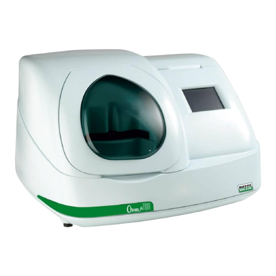
Chorus TRIO Operating Manual DESCRIPTION OF THE INSTRUMENT The Chorus TRIO analyzer is a standalone, bench-top unit that is preprogrammed with the software required to conduct the necessary tests autonomously (see Figure 1). Figure 1 The high level of automation provides the Chorus TRIO analyzer with a “walk-away” capability. -
Page 12: Front Side
Chorus TRIO Operating Manual 1.4.1 Front Side 1.4.1.1 Inserting the Strips Lifting up lid A (Figure 1) allows you to insert strips into the tray (see Figure 2). Figure 2 Each position of the carousel is numbered. Up to 30 strips may be inserted for each testing session. -
Page 13: Back Side
Chorus TRIO Operating Manual 1.4.2 Back Side 1.4.2.1 Electrical Connections The instrument’s electrical connections are located on the back left side of the instrument as described in Figure 5. 1. Power cord receptacle 2. Fuses 3. On-off switch 4. Cooling fans 5. -
Page 14: Supplied Materials
Chorus TRIO Operating Manual SUPPLIED MATERIALS The instrument is delivered in a box including the following items: Chorus TRIO analyzer with the software installed REF 81200 Bar code reader with cable Hospital-grade power cable Washing Buffer Infectious Diseases 10x, REF 86004... -
Page 15: Environmental Requirements
Chorus TRIO Operating Manual Max resolution: 0.125 mm, 5 mils Sensor: LCD solid-state (2048 pix) Default codes: code 128, code 39, Interleaved & Codebar 2 of 5 Test tube codes: 1-16 alphanumeric characters Strip and bottle codes 1-20 alphanumeric characters... -
Page 16: Safety
Protective glasses Lab coat 2.1.2 Security Labels The following labels are used on the Chorus TRIO to point out possibly dangerous conditions. Risk of puncture to hands and fingers Risk of hands bumping mechanical equipment Risk of thermal shock... -
Page 17: Name Rating Plate Label
Chorus TRIO Operating Manual 2.1.3 Name Rating Plate Label Figure 7 1. Manufacturer information 2. Instrument name and code (P/N) 3. Certification mark for conformity to CE normative for European Union 4. Mark of declaration of use for in-vitro diagnostic instruments 5. -
Page 18: Mechanical Risks
Chorus TRIO Operating Manual MECHANICAL RISKS 2.2.1 Transportation The instrument is packaged, and the internal mobile parts are secured, to allow it to be transported safely if the following precautions are taken: When loaded on a pallet, the instrument container must be moved using a pallet jack. -
Page 19: Movement Of The Sample Tray
Chorus TRIO Operating Manual 2.2.4 Movement of the Sample Tray The only moving part of the instrument which the operator might come in contact with is the carousel tray because part of it extends beyond the front of the instrument. During a run, the carousel revolves and the user might accidentally touch it, causing the run to stop. -
Page 20: Risks Regarding The Use Of Liquids
Chorus TRIO Operating Manual RISKS REGARDING THE USE OF LIQUIDS The instrument is not protected against liquid spills, and large liquid spills could seriously damage the instrument function. Do not place any containers on top of the instrument. ... - Page 21 Chorus TRIO Operating Manual ATTENTION Always wear proper protective equipment when handling bio-hazardous waste. Refer to Section 2.1.1. The waste material from the instrument must be handled as bio-hazardous waste. In the areas where contact with serum can occur, a label is affixed to the instrument indicating a biological contamination hazard.
-
Page 22: Preparation Of The Instrument
This section includes unpacking instructions and is included on the outer cover of the transport box. Please read these instructions carefully. The operations described should be performed by trained personnel authorized by DIESSE Diagnostica Senese SpA HANDLING 3.1.1 Transport and Storage The instrument is packed in a palletized cardboard box by the dimensions 75 x 84 x 75 (h) cm. - Page 23 Chorus TRIO Operating Manual The opened box appears as shown in Figure 9. Figure 9 Remove the kit and the upper part of the packing in polyethylene, as shown in Figure Remove outer cardboard casing leaving the Chorus nestling on the pallet (fig.11)
- Page 24 Chorus TRIO Operating Manual Once that has been removed the cardboard box the tool can be positioned on the work surface. Figure 11 Remove the top of the cover as follows: unscrew the hex keys (as shown in Figure 12) using the 3 mm hex key.
- Page 25 Chorus TRIO Operating Manual Lift up the cover and disconnect connector A (see Figure 14). Then remove the cover. Figure 14 Remove the packing material which vertically secures the two dispensers. Figure 15 Keep all the packing material for later use in case the instrument must be moved.
-
Page 26: Disconnection And Reinstallation
Move the tanks by themselves, using all the necessary precautions, especially for the waste tank which could contain potentially bio-hazardous liquids. Once the Chorus TRIO analyzer has been placed in its new position: Reconnect the waste tubes, taking all the necessary precautions. -
Page 27: Installation
INSTALLATION 3.2.1 Set-Up Operations to Be Performed by the User The Chorus TRIO must be installed in an environment that is suitable for its normal function. This environment must meet the electrical requirements (Section 1.6.2) and safety requirements (Section 0) described in this manual. - Page 28 Chorus TRIO Operating Manual Figure 17 The Chorus TRIO analyzer is equipped with (see Figure 17): One connection to the tank containing Washing Buffer Autoimmunity One connection to the tank containing Washing Buffer for Infectious diseases One connection to the tank containing Cleaning Solution. (This connection is also attached to the tank containing Sanitizing Solution as a substitute for the Cleaning Solution during the sanitizing cycle).
-
Page 29: Washing Buffer
Chorus TRIO Operating Manual 3.2.2.1 Washing Buffer The instrument uses both the Washing buffer for Autoimmunity that is contained in a 1 Liter tank having the code 42462 and identified with a green label and the Washing Buffer for the Infectivity that is contained in a 1 Liter tank having the code 42461 and identified with a blue label. -
Page 30: Connection Of The Waste Tank
Chorus TRIO Operating Manual 3.2.3 Connection of the Waste Tank For proper instrument function, the liquids used by the instrument must be discarded. These liquids must be collected in suitable, sealed bottles or transported into a centralized waste disposal system. -
Page 31: Connection To A Centralized Waste Disposal System
This operation must be performed with the instrument power switched off. Only the connection marked with a red band may be used to connect to the waste disposal system. If a different connection is required, order it directly from DIESSE Diagnostica Senese SpA, specifying the features of the connection needed. -
Page 32: Electrical Connections
Chorus TRIO Operating Manual Figure 21 Insert the strip slowly but firmly until you are able to feel the spring resistance; then push it in as far as it will go. To extract a strip, pull hard until the strip is released from the spring which holds it. Be careful not to spill the serum. -
Page 33: Start-Up
If desired, you may calibrate the touch screen by pressing the screen within five seconds after the blue side bar and the DIESSE logo are shown (immediately following the initial electronic check). This is described in detail in Appendix 5.2. -
Page 34: Warm-Up
Chorus TRIO Operating Manual Pressing the Skip key will allow the system check to proceed. No further checks will be performed on the lid. A warning message will appear in the first error window at the end of the check. -
Page 35: Preparations For The Check Procedure
Chorus TRIO Operating Manual before the instrument will allow you to start a run. When the software determines that more than 24 hours have elapsed since the last instrument status check, the R-List button in the Start window becomes red (see Section 4.3) and in the Check window (see Figure 86), the Optical calibration and/or Hydraulic check are shown to be needed. - Page 36 Chorus TRIO Operating Manual Figure 23 If positions 10, 20, and 30 are occupied, a warning message (shown in Figure 24) is displayed. You must position and/or remove the test strips as indicated and then press the OK key. Pressing the Exit key will interrupt the check.
-
Page 37: Initial Check Operations
Chorus TRIO Operating Manual Figure 25 ATTENTION Pressing the Skip key allows you to skip this waiting time; but the optic calibration will not be performed, even if necessary, because the optic calibration requires that the instrument has reached the set temperature. -
Page 38: Washing Buffer Priming
Chorus TRIO Operating Manual Figure 26 Note: Before performing a new cycle, the instrument automatically sets an internal software flag and a buffer priming will be done before running the test. If there are any outstanding checks, the status bar will show the message “Not ready”. The check window (see Section 4.10) can be used to view the elements that need to be checked. -
Page 39: Washing Buffer Priming Operations
Chorus TRIO Operating Manual Figure 27 The tank must be filled at least with the 25% of solution. Following the Washing Buffer priming step, you must remove any strips present in the positions 7 and 11 on the tray (Figure 28). -
Page 40: Strips, Calibrators And Qc
Chorus TRIO Operating Manual The deep priming consists of: First cleaning of whole hydraulic circuit, dispensers included First standard priming Second cleaning of whole hydraulic circuit, dispensers included Second standard priming STRIPS, CALIBRATORS AND QC 3.6.1 Strips... -
Page 41: Insertion And Extraction
Chorus TRIO Operating Manual 3.6.1.1 Insertion and Extraction The strip is held in place in the tray by a spring stop. When inserting the strip, it is necessary to push the strip in with some force to overcome the resistance of the spring. The same is true when extracting the strip since it requires some force to pull it free. -
Page 42: Use
Chorus TRIO Operating Manual 3.6.3 QC 3.6.3.1 Use The QC is processed as any sample and its code represents the sample code. Therefore, to allow the instrument to recognize that the strip was loaded with the QC insert, in the column corresponding to the sample code, or in C-List, or in the R-List, near the strip code, enter the QC code either by reading it with the external bar code reader or by entering it manually. -
Page 43: Replenishing Operating Liquids
Chorus TRIO Operating Manual Keep the area surrounding the instrument clean using standard cleaning solutions as appropriate for the type of work surface. When cleaning, make sure to inspect the depressions in the tray where the strips are inserted. If you find these areas contain moisture or are wet, call for technical assistance. -
Page 44: Sanitizing
Such a cycle includes using an antibacterial solution supplied by DIESSE Diagnostica Senese SpA to wash all the parts that came into contact with a whole or diluted solution. This procedure helps prevent mold from growing in the hydraulic lines and must be performed once a week. -
Page 45: Scheduled Maintenance
Chorus TRIO Operating Manual Check and possible filling of the liquids Emptying the waste tank Replacing paper in the printer Performing the internal cleaning procedure at the end of the test day Execution of the sanitizing cycle when the instrument requires it When the instrument is switched on, it performs the Initial Check that checks all system functions (electronic, mechanical, hydraulic). -
Page 46: Use Of The Instrument
Job List (J-List) is the list which associates all the sample codes with the test codes. In the Chorus TRIO system, the sample must be transferred to a ready-to-use strip that is specific for a particular test. Each strip is provided with a bar code that specifies the type of test (test-code) it can be used with and a numeric code that differentiates it from all other strips manufactured by DIESSE. -
Page 47: Connection To Host Computer Not Available
Chorus TRIO Operating Manual 4.1.3.1 Connection to Host Computer Not Available If a connection to the host computer is not available, the following procedure is recommended: 1. Using the paper J-List, assemble the strips necessary to perform the tests 2. Place all the strips in the tray (it is not necessary to insert the strips in order from the paper J- List), taking care to always place the calibrators in the first positions of the tray 3. -
Page 48: Description Of The Windows
This shows the company logo, the name of the instrument, the current time, and the date. Status Bar: This describes the status of the instrument. A white background shows that the Chorus TRIO analyzer is ready and/or running. A red, yellow, or magenta colored background indicates a problem interfering with normal operation. -
Page 49: Start Window
Chorus TRIO Operating Manual START WINDOW The START window appears after the initial checks are complete. This window enables you to access all the different functions of the instrument. There is no Exit key as this is the opening screen. -
Page 50: Manual Editing
Chorus TRIO Operating Manual MANUAL EDITING Manual editing replaces the use of the bar code reader in the following cases: Manual introduction of codes which the bar code reader is unable to read Correction of erroneous codes Addition of personalized codes 4.4.1 Description of the Commands in Editing Mode... -
Page 51: Editing In Insert Mode
Chorus TRIO Operating Manual 4.4.2 Editing in Insert Mode When Insert mode is selected, only the cursor is visible. Figure 32 Insert the desired code by typing the characters on the keyboard. Press the OK key to save the code and return to the previous window. -
Page 52: Editing In Modify Mode
Chorus TRIO Operating Manual 4.4.3 Editing in Modify Mode In the modify mode of editing, the bar shows the whole code selected, with the cursor positioned after the last character. Figure 34 The characters to be modified may be deleted by pressing the Back key. -
Page 53: The C-List Window (Coupling List)
Chorus TRIO Operating Manual THE C-LIST WINDOW (COUPLING LIST) The C-List window shows the list of the associations between samples and tests (see Section 4.1). Keyboard: accesses the editing window Delete: deletes the current C-List or the line selected (a window appears allowing... -
Page 54: Insertion Of The First Code
Chorus TRIO Operating Manual ATTENTION It is not possible to start the compilation of a C-List unless at least one sample code has been inserted, because each test must be associated with a sample code that is already present. An empty C-List, therefore, will disable all of the keys except the Edit and Exit keys. -
Page 55: Insertion Of The Next Codes
After entering the first sample code, you may then enter: Sample code/QC sample code/Calibrator code Strip codes The Chorus TRIO automatically recognizes a sample strip code, a QC (quality control) code, or a calibrator code. 55 of 132 Software Release 3.2.x and 4.0.x Rev 1.3 (06/2016) - Page 56 Chorus TRIO Operating Manual Entering a SAMPLE / QC / CALIBRATOR Code To enter a new code, two methods are available: 1. Scanning using the bar code reader 2. Using the keyboard to enter: a valid Sample code (15 characters maximum) ...
-
Page 57: Modification Of A Code
Chorus TRIO Operating Manual Entering a STRIP Code To enter a strip code after the first sample, two methods are available Scanning by the bar code reader. Typing a valid strip code using the keyboard. The strip code will be displayed in the same row that the sample code is displayed. - Page 58 Chorus TRIO Operating Manual Figure 46 Figure 47 ATTENTION The Modification operation does not delete the code but rather changes the code to be a new valid sample/QC/Calibration code. Modification of a STRIP Code Press the Modify key and, with the selection bar located in the Test column as displayed in Figure 49, two methods are available for modifying the code: Scan the code using the bar code reader.
-
Page 59: Insertion Of A Strip Code In An Empty Position
Chorus TRIO Operating Manual Figure 50 ATTENTION The Modification operation does not delete the code but rather changes it to a new, valid strip code. 4.5.1.4 Insertion of a STRIP Code in an Empty Position In case a position for a strip code has been... -
Page 60: Duplication Of A Sample Code
Chorus TRIO Operating Manual Move the selection bar to highlight the free position (the fifth position in Figure 52). Enter the new code by: Scanning using the bar code reader Typing using the keyboard The new strip code will appear in the desired position (Figure 52). -
Page 61: Compilation By Host Connection
Chorus TRIO Operating Manual 4.5.1.6 Compilation by Host Connection It is possible to obtain the list of tests that must be performed on the samples from the LIS. Follow the steps below Open the C-List window and compile the C-List by typing or scanning the sample codes for your daily job list. -
Page 62: Job List To C-List
Chorus TRIO Operating Manual 4.5.1.7 Job List to C-List To transform the Job List sent by the host computer, it is necessary to: Enter the Modify mode Scan the strip code corresponding to that sent by the host... -
Page 63: The R-List (Running List) Window
Chorus TRIO Operating Manual THE R-LIST (RUNNING LIST) WINDOW The R-List shows the status of the strips and of the samples that have been dispensed before starting the cycle. The R-List is defined after the identification procedure during which all the tray positions are scanned and the inserted strips are identified by reading their bar codes. - Page 64 Chorus TRIO Operating Manual The commands available in the R-List window are: Keyboard Opens the keyboard to allow you to manually enter a code (see Section 4.4). The keyboard button may be disabled (shown in red) depending upon whether or not a code may be entered (see sample/test command).
- Page 65 Chorus TRIO Operating Manual Figure 61 shows an example of R- List with a successful strip’s codes identification process. The software automatically given some sample code according to the strip position in the list Figure 61 - R-list example Figure 62 shows the yellow cursor in the second row.
-
Page 66: Using The R-List
Chorus TRIO Operating Manual In figures 62bis and 63bis two examples, similar to those present in the figures 62 e 63, are shown. The unique difference is that the automatic row scroll mode is off and the scroll from one to another row is performer using the buttons "+"... - Page 67 Chorus TRIO Operating Manual Figure 64 To start the R-List function, press Yes and continue. The system revolves the carousel and identifies the strips that have been inserted. After the identification process, the R-List window is displayed. An example is shown in Figure 65.
- Page 68 Chorus TRIO Operating Manual The errors present in this example must be corrected as shown below. First, dispense calibrator TX-G into strip number 1 and calibrator Glia-A into strip number 8. Figure 66 shows the new information. Figure 66 STR RD in position 4 stands for strip code reading error. To remove this error, enter the strip code manually using the keyboard.
- Page 69 Chorus TRIO Operating Manual REMARKS Identification Errors The list of errors that may appear during the identification procedure is described in Section 5.4.2.4 along with an explanation of what you can do to solve or remove them. Sample Codes The sample code that is coupled with a strip in the C-List is automatically entered on the sample column when the bar code identifies the strip on the tray.
-
Page 70: Running The Cycle
Chorus TRIO Operating Manual RUNNING THE CYCLE Pressing the RUN button in the R-List window starts the cycle. Some warnings will be displayed to inform you about the conditions under which the cycle will be performed. Figure 68 Sample Error If any strips give an error, a message will appear asking you to confirm that you want to start the cycle (see Figure 68). -
Page 71: Liquid Level Control
Chorus TRIO Operating Manual 4.7.1 Liquid Level Control The cycle starts only if the tanks are filled with enough solution to perform the test. ATTENTION The quantity of the Washing Buffer Solution and the Cleaning Solution required depends on the number of tests to be executed. - Page 72 Chorus TRIO Operating Manual Second - the speed at which the test is performed : short step time (SST) long step time (LST) so that, it is possible to have the the following four cycles 1. Infectious test at SST together the no buffer test at SST 2.
-
Page 73: Preliminary Operations
Chorus TRIO Operating Manual 4.7.4 Preliminary Operations Before starting the run, some preliminary operations are performed on the strips. 4.7.4.1 Warming the Tray After any message is confirmed, the run starts. The first operation is to check if the tray is at the temperature required by the test. -
Page 74: Strip Shaking
Chorus TRIO Operating Manual 4.7.4.4 Strip Shaking Before that the cycle starts, it is necessary to shake the strips so that all the solutions are well mixed. The window that is displayed while the tray can be heard to be vibrating is shown in Figure 73. - Page 75 Chorus TRIO Operating Manual Short for “time to expire”) Indicates the time, expressed in hours and minutes, required to finish the run. The two letter-code for the operation being performed on the strip. The possible values are: TR = liquid transferring from one well to another...
- Page 76 Chorus TRIO Operating Manual Session aborted due to thermoregulation failure Session aborted (no empty position for priming) Session aborted (priming failed) Session aborted (no devices to be processed) If the error that occurred may be bypassed or is only a warning, the status bar becomes respectively purple or yellow and the error list may be opened by pressing the center of the status bar.
-
Page 77: Cycle Results
Chorus TRIO Operating Manual 4.7.6 Cycle Results At the end of the cycle, the window in Figure 77 appears, reporting the results of the last cycle performed followed by all of the strip errors. Print: prints the results Host: sends the results to the host... - Page 78 Chorus TRIO Operating Manual The codes used in the columns are as follows: The position of the strip on the tray. Smp Code: The sample code. If preceded by the letter T, the strip has been processed with a temperature error and the result might not be correct.
-
Page 79: Sanitizing Need
Chorus TRIO Operating Manual 4.7.6.2 Sanitizing Need In case the working cycle was started disregarding the sanitizing request, after the header of the report, the following text is printed: “This session was executed on a non-sanitized instrument” to indicate that the results of that session might be invalidated by the state of the hydraulic system. -
Page 80: The Sessions Archive
Chorus TRIO Operating Manual THE SESSIONS ARCHIVE 4.8.1 The Archives Window This window presents a list of the runs performed, displaying the date and time of execution for each one. The instrument can store up to 20 runs; the most recent runs overwrite the oldest ones. -
Page 81: The Utilities Window
Description of the content of the utility window “3.1.2 V” Firmware release of the software installed in Chorus TRIO Serial Number: Serial number of the Chorus TRIO analyzer (serial number/month of production/year of production). Method release: Release of the test methods stored. -
Page 82: Settings Window
Chorus TRIO Operating Manual 4.9.1 Settings Window 4.9.1.1 Clock Setting Store: saves the date and time that have been set (only enabled in case of modification) Exit: returns to the settings window : they modify date and time Figure 82 4.9.1.2 Audio Setting... -
Page 83: Monitor Brightness Setting
Chorus TRIO Operating Manual 4.9.1.3 Monitor Brightness Setting Store: saves the level of brightness that has been set Exit: returns to the settings window Scrollbar: increases/decreases brightness level Figure 84 4.9.1.4 Language Setting Italian: permits to set the language of the... -
Page 84: Check Window
Chorus TRIO Operating Manual 4.10 CHECK WINDOW The check window shows the state of the instrument and allows access to the various controls necessary to re-establish proper function. Restore: determines which checks should be performed and starts those that are... - Page 85 Chorus TRIO Operating Manual Hydraulic Check: Indicates (in red with the wording “required“) when it is necessary to perform a hydraulic check (if more than 24 hours have passed or if the previous check was interrupted). Liquid in the Washing Buffer Circuit: Indicates which liquid is present in the buffer circuit.
-
Page 86: Errors Window
Chorus TRIO Operating Manual 4.11 ERRORS WINDOW If errors are found during the initial check procedure, the following summary appears: Print: prints the list of errors found with their numeric identification corresponding description Silent: disables the audible alarm Report: prints all the errors with numeric... -
Page 87: Appendixes
Chorus TRIO Operating Manual APPENDIXES WINDOWS FLOW-CHART Figure 88 87 of 132 Software Release 3.2.x and 4.0.x Rev 1.3 (06/2016) -
Page 88: Touch Screen Calibration
Chorus TRIO Operating Manual TOUCH SCREEN CALIBRATION You may calibrate the touch screen during the startup procedure of the instrument by pressing the screen within 5 seconds from the moment the first empty screen is seen (see Figure 89). Figure 89... - Page 89 Chorus TRIO Operating Manual Keep press the yellow cross, which appears at the right side of the screen. If the pressure on the cross is not kept for at least 5 seconds or if the pressure is not constant, the instrument will ask you to repeat the operation.
-
Page 90: Analytic Evaluations
Chorus TRIO Operating Manual ANALYTIC EVALUATIONS The final test result (titration) is determined by means of dedicated algorithms that analyze the results read at optical densities (OD), using three optical channels, in two wells of the strip (well#5 and well#6). Specifically, the optical densities of well 5 are detected using Ch1, Ch3 and Ch5; the optical densities of well 6 are detected using Ch2, Ch4 and Ch6. -
Page 91: Kinetics Acceptance
Chorus TRIO Operating Manual 5.3.1 Kinetics Acceptance At the end of the test concerning either a sample, a calibrator, or a QC, the kinetics are analyzed to determine congruence by means of the following checks: 5.3.1.1 Initial Value Check with 650nm filter In case of increasing kinetics, if it turns out that: ... -
Page 92: Qualitative Tests
Chorus TRIO Operating Manual 5.3.2 Qualitative Tests 5.3.2.1 Calibration During the qualitative tests is determined, for each lot of a test, the optical density of the calibrator: For test with 650nm filter the optical density of the calibrator is determined by the following formula: = (OD3 –... -
Page 93: Quality Control
Chorus TRIO Operating Manual The index value is used on a linear scale, as the one of the Figure 95, to evaluate whether it is positive, negative, or doubtful (doubtful area). In the final report, the result appears as P, N, or E with the indication of the index value. -
Page 94: Quantitative Test
Chorus TRIO Operating Manual 5.3.3 Quantitative Test 5.3.3.1 Calibration During the quantitative tests is determined, for each lot of a test, the optical density of the calibrator: - For test with 650nm filter the optical density of the calibrator is determined by the following formula: = (OD3 –... -
Page 95: Titration
Chorus TRIO Operating Manual I1 = I3 = I4 = I5 = ODcal ODcal ODcal ODcal Figure 96 5.3.3.2 Titration The sample is processed with one strip of a test batch and its optical density is thus determined: - For test with 650nm filter = OD3 –... -
Page 96: Quality Control
Chorus TRIO Operating Manual It is calculated as follows: If T and T represent the concentrations (in ng/ml) determined by the Tg test in cuvettes 5 and 6 of the strip, then the formula is: R% = (T ) *100 10 ng/ml 5.3.3.4 Quality Control... -
Page 97: Quality Control
Chorus TRIO Operating Manual then the sample is said to be strongly positive IgG. The sample is defined as DIL. In this case, the sample will be diluted, as described in the instruction for use of the product, and the analysis will be repeated. -
Page 98: Quality Control With Direct Index
Chorus TRIO Operating Manual 5.3.5.2 Quality Control with Direct Index After determining = OD3 – OD1 Calculate the index: = OD / OD And make sure that: ≥ I ≥ I upper lower Where the limits I are found in the QC bar code. -
Page 99: Cft
Chorus TRIO Operating Manual 5.3.6 CFT The test foresees the execution at the same time of the following: Anti-complementary power of the sample (ACP) in well 6 (blue curve) Reaction Sample-Antigen in well 5 (green curve) The cycle is carried out in 3 reading operations (R1, R2, R3) for both the reaction with the antigen and the anti-complementary power (ACP). - Page 100 Chorus TRIO Operating Manual > OD1 x ACP% ACP. The result is “A.C.P.” (Anti-Complementary Power of the sample) fig 98. OD 3 < OD1 x ACP% ACP. The readings concerning the antigen well are evaluated and the routine goes on to phase c)
- Page 101 Chorus TRIO Operating Manual ACP % A.C.P ACP % >1/128 ACP % Figure 98 101 of 132 Software Release 3.2.x and 4.0.x Rev 1.3 (06/2016)
- Page 102 Chorus TRIO Operating Manual 102 of 132 Software Release 3.2.x and 4.0.x Rev 1.3 (06/2016)
-
Page 103: Troubleshooting
Chorus TRIO Operating Manual TROUBLESHOOTING An error detection procedure is present on the instrument, running in the background, in order to alert you of possible anomalies during functioning by means of a message on the status-bar. This section reports the actions that should be taken in case these errors occur. -
Page 104: Recoverable Errors
Chorus TRIO Operating Manual 5 to 7 Not used Strip Thermometer Description: The strip thermometer does not respond. Strip Temp. Adj. Description: Strip thermostat out of range. Instrument Thermometer Description: The instrument thermometer does not respond. Instr. Temp Adj. Description: Instrument thermostat out of range. -
Page 105: Fatal Errors
Chorus TRIO Operating Manual 5.4.2.3 Fatal Errors ATTENTION The errors listed in the section below are called fatal because the instrument cannot recover from them and whatever process was in progress will be aborted. Because of that, no corrective actions are suggested. You must contact your local Customer Support for field service. - Page 106 Chorus TRIO Operating Manual Strip Temp. Adj. Description: Strip thermostat out of range. Instr. Thermometer Description: The instrument thermometer does not respond. Instr. Thermo Adj. Description: Instrument thermostat out of range. The four temperature errors (67-70) constitute fatal errors when the instrument is in standby.
- Page 107 Chorus TRIO Operating Manual Washer #1 Assembly Description: Washer 1 home position cannot be reached after motor motion. Washer #2 Assembly Description: Washer 2 home position cannot be reached after motor motion. Washer #3 Assembly Description: Washer 3 home position cannot be reached after motor motion.
- Page 108 Chorus TRIO Operating Manual - in the initial check to test partial emptying of the container. Not used Waste Pump Fault Description: Error found at the start of the hydraulic check due to damage to the waste pump. Wsh#1 Coll. Well Filling...
- Page 109 Chorus TRIO Operating Manual 250 μl Syringe Disp. Description: Error found at the start of the hydraulic check due to incorrect dispensation of liquid from the 250 ul syringe into the test strip well. Not used Washer#1 Suct. (Well#5) Description: Error found at the start of the hydraulic check, due to incorrect aspiration of washer 1 from well n°5 of the test strip.
- Page 110 Chorus TRIO Operating Manual Washer#3 Suct. (Well#6) Description: Error found during the hydraulic check due to incorrect aspiration of washer 3 from well number 6 of the test strip. CS Solenoid Valve the Cleaning Solution doesn’t flow properly in the wash tubing.
- Page 111 Chorus TRIO Operating Manual Channel #6 Receiver Description: Optical channel 6 is not lighted. Channel #1 Offset Description: The offset regulation of optical channel 1 has failed. Channel #2 Offset Description: The offset regulation of optical channel 2 has failed.
-
Page 112: Identification Errors
Chorus TRIO Operating Manual Channel #1 Air (650) Description: The white balancing of optical channel 1 has failed. Channel #2 Air (650) Description: The white balancing of optical channel 2 has failed. Channel #3 Air (650) Description: The white balancing of the 650nm portion of optical channel 3 has failed. -
Page 113: Strip Processing Errors
Chorus TRIO Operating Manual NO CALIB Description: The corresponding strips are part of a non-calibrated batch. Corrective action Calibrate the lot of the test. CAL POS Description: The calibrator is positioned after a strip with the same code. The calibrator must precede the relative strip on the tray. -
Page 114: Analytical Errors
Chorus TRIO Operating Manual The error code is D1. Corrective action Save the strip and contact Customer Support. If the error is occasional, you may continue to work. DRILL#2 Description: Dispenser 2 has not perforated the strip well correctly. The error code is D2. - Page 115 Chorus TRIO Operating Manual Corrective action Contact Customer Support. CAL OVR Description: The sample is inserted in a run where its relative calibrator has failed. Corrective action After the lot has been calibrated, recalculate this test using the option provided in the ARCHIVE / VIEW window.
-
Page 116: Cycle Messages
Chorus TRIO Operating Manual 5.4.3 Cycle messages Messages regarding the test results Description: Sample too concentrated. Dilute as specified in the instructions for use of the kit. Corrective action Dilute the sample and repeat the test and/or contact Customer Support. -
Page 117: Identification Of The Tanks
Chorus TRIO Operating Manual IDENTIFICATION OF THE TANKS The identification is started: for all tanks every time the instrument is switched on; for a specific tank that has to be substituted as soon as the probe from that tank is removed;... -
Page 118: Identification Of The Buffer Solution For Autoimmunity
Chorus TRIO Operating Manual Subsequently, you will be requested to insert the probe into the tank (not empty) the cleaning solution that was previously identified (Figure 101). Using the Skip key, it is possible to skip this check (Figure 101). - Page 119 Chorus TRIO Operating Manual As soon as removal of the probe is detected, the following window (Figure 104) will request reading of the bar code. Whenever a bar code reader is not available, it is possible to enter the code manually by pressing the Edit key (code 42462).
-
Page 120: Identification Of The Buffer Solution For Infectious Diseases
Chorus TRIO Operating Manual If the Skip key is pressed, the instrument will not permit you to start priming autoimmunity buffer solution which was selected as current buffer. It will not be possible to start a working cycle until the buffer solution is identified correctly. - Page 121 Chorus TRIO Operating Manual As soon as removal of the probe is detected, the following window (Figure 108) will request the reading of the bar code. Whenever a bar code reader is not available, it is possible to enter the code manually by pressing the Edit key (code 42461).
- Page 122 Chorus TRIO Operating Manual If the Skip key is pressed, the instrument will not permit you to start the priming of the autoimmunity buffer solution which was selected as current buffer. It will not be possible to start a working cycle until the buffer solution is identified correctly.
-
Page 123: Chorus Trio To Lis Connection
The following diagrams explain the two possible paths by which data can be exchanged between a Chorus and the LIS (laboratory information system) 1. Before running samples, the Chorus TRIO transmits the Sample List to the LIS and receives back the related Job List. -
Page 124: Interface Programming
Chorus TRIO Operating Manual 5.6.2 Interface Programming The connection consists of a standard RS-232C serial interface. A pinout diagram for the connection cable is shown in the picture below. Pins shown as unconnected may either be connected or not, as desired, beecause they are not used. -
Page 125: Serial Communication Frame
Chorus TRIO Operating Manual Port Parameter HOST EXT-SERV Note: Bitrate setting affects the HOST connector only. EXT-SERV connector bitrate is fixed at 38400 baud. Note: HOST connector requires firmware version 2.10 or above. Note: Used byte order is little-endian: bytes are stored from the less significant to the most (e.g., a word field of value 258 is coded as 0x0201). -
Page 126: Enquiry
0x05 5.6.5 Sample programming After receiving each sample code that has been entered, the computer sends to the Chorus TRIO the list of tests to be executed on that sample. This is called the Job-List (J-List). After establishing a connection between the computer and the Chorus TRIO (Section 5.6.4), the instrument sends the following frame for each inserted sample: ... - Page 127 SampleCode field contains 19 characters (including trailing character). Note: Since the total number of storable tests of the Chorus TRIO is limited, the computer must not send a number of TestID records greater than StorableRec. Therefore, there is the possibility that not all of the relative IDs for a given sample can be sent because of space.
- Page 128 Chorus TRIO Operating Manual Field Description Value Data type Bytes JlistEnd J-List end command 0xD3 byte The Computer closes the connection with the following frame: Computer Chorus TRIO Example: No tests have to be executed on sample S1; ANA-Screen (ID1) has to be executed on sample S2;...
-
Page 129: Result Management
Chorus TRIO Operating Manual 5.6.6 Result Management In the result window, after each cycle or anytime from the session archive, the Chorus TRIO can send the computer sample results in order to archive or elaborate upon them. After establishing a connection between the computer and the Chorus TRIO (Section 5.6.4), the instrument sends the... - Page 130 Chorus TRIO Operating Manual Chorus TRIO Computer 0x02 0x32 0xD7 0x53 0x33 0x00 0x00 0x00 0x00 0x00 0x00 0x00 0x00 0x00 0x00 0x00 0x00 0x00 0x00 0x00 0x00 0x00 0x41 0x4E 0x41 0x48 0x45 0x2D 0x70 0x4E 0x30 0x2E...
-
Page 131: Ec Declaration Of Conformity
Chorus TRIO Operating Manual EC DECLARATION OF CONFORMITY 131 of 132 Software Release 3.2.x and 4.0.x Rev 1.3 (06/2016) - Page 132 Chorus TRIO Operating Manual Distributed by 132 of 132 Software Release 3.2.x and 4.0.x Rev 1.3 (06/2016)
Need help?
Do you have a question about the Chorus TRIO and is the answer not in the manual?
Questions and answers