Advertisement
Quick Links
Advertisement

Subscribe to Our Youtube Channel
Related Manuals for Diesse VES MATIC CUBE 80


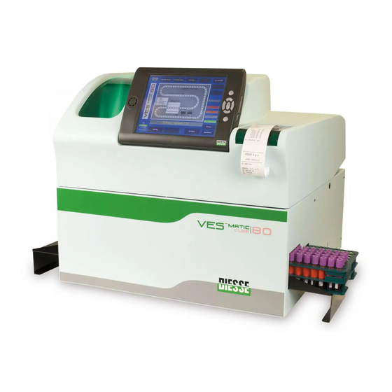
Summary of Contents for Diesse VES MATIC CUBE 80
- Page 1 Installation Guide Revision 2.00 of 04/11/2009 English Diagnostica Senese S.p.A...
-
Page 2: Table Of Contents
- Installation Guide SUMMARY ECHNICAL PECIFICATIONS ......................... 3 TORAGE AND RANSPORT ........................4 REPARATION AND HECKS EFORE NSTALLATION .................. 5 NPACKING ............................6 LACEMENT ............................9 NSTALLATION ........................... 10 UNCTIONAL TARTUP ROCEDURE ...................... 11 NALYTICAL TARTUP ........................13 Revision 2.00 of 04/11/2009 Page 2 of 33... - Page 3 - Installation Guide ECHNICAL PECIFICATIONS Power supply Europe: 230Vac@50Hz; Usa/Canada: 110-120Vac@60Hz Absorbed electrical power 265VA Fuses 2 x 5,0A T (5 x 20 mm) UL-CSA Dimensions 650 x 580 x 690 mm ( l x h x p ) Weight 45 Kg Operational from +15 to +35°C...
-
Page 4: Storage And Transport
- Installation Guide TORAGE AND RANSPORT Given the size and weight of the device, any movement of the instrument has to be executed by at least two people. The Vesmatic Cube 80 is a precision instrument and has to be handled as such. Inappropriate handling can harm the internal components and cause mechanical damage. -
Page 5: Preparation And Checks Before Installation
- Installation Guide REPARATION AND HECKS EFORE NSTALLATION The following conditions must be enforced for the safety of the instrument and the operator: The power network (installation category II) must be compatible with the electrical requirements, specifications and current indicated on the electric power plate supplied with the instrument;... -
Page 6: Unpacking
- Installation Guide NPACKING Given the size and weight of the device, any movement of the instrument has to be executed by at least two people During the movement of the device avoid jarring and excessive inclination that could damage the instrument. Unpacking of the instrument Execute the phase of unpacking as described and shown below: Remove the screws of the wood box:... - Page 7 - Installation Guide Fig. 4.3 Apply the supplied handles to the instrument to execute the transfer of the instrument, as shown in sequence (Fig.4.4) Fig. 4.4 Check that the packing list corresponds with the supplied material. Should the instrument and/or the accessories supplied turn out to be damaged during transport, notify the delivery personnel and the Assistance Centre.
- Page 8 - Installation Guide Revision 2.00 of 04/11/2009 Page 8 of 33...
-
Page 9: Placement
- Installation Guide LACEMENT The environment intended for this instrument is the analysis laboratory. For safety reasons and given the type of exams that it executes, the instrument has to be placed far from sources of heat, in zones non accessible to liquids, in environments free from dust and on perfectly flat work benches that are not subject to shocks or vibrations. -
Page 10: Installation
- Installation Guide Never move the instrument after it is properly installed. Should movement or relocation of the instrument be necessary, a re-verification of the conditions listed in this paragraph would be required before using the instrument again. Whenever the instrument will not be used or an extended period of time it is suggested that it be disconnected from the power source and covered. -
Page 11: Functional Startup Procedure
- Installation Guide Assure that the power switch is in the OFF <<0>> position before continuing. 5. Executed connections with the external instruments. 6. Remove the tape blocking the window of the printer compartment and assure that the role of thermal paper is positioned correctly and free (free it from possible presence of elastic security band used during transport. - Page 12 - Installation Guide 8. Now from the service menu, in the “Procedures” section (located in the bottom-right corner of the display) end select the “TEST LOAD SAMPLE FROM RACK” end push exec. • If the clamp don’t correctly goes on the tube you can change the parameter “CLAMPH RACK POS1”...
-
Page 13: Analytical Startup
Labelling procedure and maximum number of labels compatible with the analytical system. Ves Matic Cube 80 models are designed to work with a maximum of two labels attached to the same sample tube, but they must not be overlapping (Fig. 1). - Page 14 - Installation Guide The internal barcode reader, placed inside the Preparor Module, is: • mechanically set to read labels attached to the tube at least mm.3 above the the start of bottom roundness (Fig. 2, ). • programmed to read barcodes placed at 90° degrees compared to the reading rays, that is the barcode must be placed to cross horizontally the tubes vertical axis (Fig.
- Page 15 - Installation Guide NOTICE: Verify, before loading the instrument, that the labels adhere perfectly to the tubes otherwise the unattached parts could cause frictions during the mechanical movements of the groups (especially inside the inserting, ejecting and sorting module), creating inserting and ejecting problems in the analitycal chain and possible blocks of the reading sensors.
- Page 16 - Installation Guide Fig.4 Labelling: Incorrect label for Ves-Matic Cube 80 16 of 33 Revision 2.00 of 04/11/2009...
- Page 17 - Installation Guide Materials Ves-Matic Cube 80 Fresh blood samples collected from the laboratory ( suggested N° 50 ) Note: Each instrument executes the analysis of the samples directly from test tubes being used on the blood cell counter in the laboratory, it is therefore not necessary to do a double drawing nor a transfer of biological material.
- Page 18 - Installation Guide List of parameters Read Parameters default values for “Vescube.ini” [READ_PARAM] DELTA_LIMIT=11 SH_THRESHOLD=100 START_POINT_M1=180 END_POINT_M1=0 START_POINT_M2=140 END_POINT_M2=0 DIFF_DIGITS=10 PERC_FILTER_MIN_ABS=20 DIGITS_RATE=50 M1M2_MAX_DIFF_ESR=20 PERC_CORR_ESR=60 RETRY_VES=140 NUM_MAX_RETRY_VES=0 MAIN_METHOD=1 M1M2_MAX_DIFF_ERR=1 SL_THRESHOLD=110 M3_WHIT_M2_NOT_ZERO=0 OVERDILL_ENABLE=0 18 of 33 Revision 2.00 of 04/11/2009...
- Page 19 - Installation Guide Note : -Using the Greiner Vacuette tubes end sarstedt tubes it is suggested to set the parameter START_POINT_M2 as follows: START_POINT_M2=120 must be equals. END_POINT_M1 END_POINT_M2 Procedure 2 Log file activation. It’s very important to activate the Log.txt file . In the Vescube.INI file check and eventually change the following parameter.
- Page 20 - Installation Guide Procedure 3 Values for M1 and M2 activation . Procedure directly show the values for M1 and M2 obtained from reader1 and reader2 on video during the run . Open the Service Menu’ as described Access password => “131313” After the password the software comes back to the main windows .
- Page 21 - Installation Guide Procedure 4 ANALYSIS RESULTS , CALCULATION ALGORITHMS and Error Evaluation The reading sensors that measure the height of the blood inside the tubes are composed by an high power white led and an analogue light sensor. The reading procedure executed by Reader 1 and Reader 2 is the following: - The Reading sensor goes to the end position, that corresponds to the top position, immediately under the cap of the tube.
- Page 22 - Installation Guide Start point of blood Top of the Tube Bottom of the Tube READINGS Fig. 5.2 Start point of blood In fig. 5.2 are explained the various points of the readings curve with their physical correspondence on the tube. The above curve is related to the First Reading of the sample, that is immediately after the Mixing.
- Page 23 - Installation Guide Final Start point of blood Top of the Tube Bottom of the Tube READINGS RED CELLS PLASMA Fig. 5.3 Final reading level Initial blood level In fig. 5.3 is represented the same sample of fig. 5.2, but read after the sedimentation time of 20 minutes.
- Page 24 - Installation Guide Detecting the “Start of Blood” Point Two methods are used to elaborate the readings curves and detect the correct Start of Blood Point. The two methods are completely independent the one respect to the other, and are used to have a double security on the reliability of the readings, in fact if the points calculated by the two methods are different, a warning is signaled for that result to alert the user that it’s an “Uncertain result”.
- Page 25 - Installation Guide Method 3 is based on a particular function of squaring signal to eliminate all spikes present. The software draws a new curve and after applies again M1 and M2 . data To activate the error message set the following param at 1. M1M2_MAX_DIFF_ERR=1 In the Ves-matic cube it’s possible to have 4 different alert data.
- Page 26 - Installation Guide Method 1 & Method 2 cross-verification In the printout of the results, and in the data sent to the host computer the following criteria are applied: If the difference between the two ESR calculated by Method1 and Method2 is lower than the M1_M2_MAX_DIFFERENCE the final ESR is the average value between those values, and is a valid result.
- Page 27 When you change the parameters remember that END POINT M1 and END POINT M2 ought to be same. You can download the software at the following address : http://www.diesse.it/support/ves/vescube Please note that access to the site is submitted to a password ; in case you do salesoffice@diesse.it not have your password please contact After downloading unpack the file.
- Page 28 - Installation Guide visually ok send the log.txt file to the tech assistance . Check the tube Volume and If the check results label visually ok send the log.txt file to the tech assistance . Res * Check tube and M1 Label and M2 reading;...
- Page 29 - Installation Guide Graph 1.1 Manley’s Nomogram RESULTS To evaluate the precision between runs use a very simple grah. like the one in the follwing figure theoric line run 2 run 1 All samples have to stay within the red limits . 29 of 33 Revision 2.00 of 04/11/2009...
- Page 30 - Installation Guide theoric line run 2 run 1 If one or more samples are out of range is important to evaluate the patological signifiance: 30 of 33 Revision 2.00 of 04/11/2009...
- Page 31 - Installation Guide e.g. case 1 run 2 82,62 run 1 In this case it is possbile ot accept the test as valid since there is no risk of invalidating the clinical meaning of the test 31 of 33 Revision 2.00 of 04/11/2009...
- Page 32 - Installation Guide Case 2 20,62 run 2 run 1 In this case the test has to be considered not correct since the repetition of a sample changes its state, from normal to pathologic and vv. Note 1: Before processing the samples assure that they are: a) fresh or stored at 4°c b) wait for them to arrive at room temperature WARNING:...
- Page 33 - Installation Guide Use the following evaluation chart. ALL SAMPLES IN THE LIMITS +/-12 ============== ============== WITHOUT ERROR CODE TEST PASSED PRESENCE OF (*) OR DIFFERENT ERROR CODE REMOVE RESULTS WITH (*) OR ERROR CODE FROM THE GRAPH ALL SAMPLES IN THE LIMITS +/-12 TEST FAILED ! PERFORM MORE CONTROLS OR SEND lOg...
Need help?
Do you have a question about the VES MATIC CUBE 80 and is the answer not in the manual?
Questions and answers