
Subscribe to Our Youtube Channel
Related Manuals for Brune B 600


Summary of Contents for Brune B 600
- Page 1 H u m i d i t y S y s t e m s - s i n c e 1 9 2 8 OPERATING INSTRUCTIONS Evaporative humidifier...
- Page 2 Information on the operating instructions These instructions enable the safe and efficient use of the evaporative humidifier B 600 Professional. The instructions are part of the humidifier and must be kept in the immediate vicinity of the unit and accessible at all times.
-
Page 3: Table Of Contents
Table of contents 1. The B 600 evaporative humidifier ............4 6.3 Cleaning work ..................27 1.1 General overview ..................4 6.3.1 Monthly cleaning ................. 27 1.2 Touch display ....................5 6.3.2 Change filter ..................29 1.3 Radio humidity transmitter ..............5 6.3.2.1 Change evaporation filter ............. -
Page 4: The B 600 Evaporative Humidifier
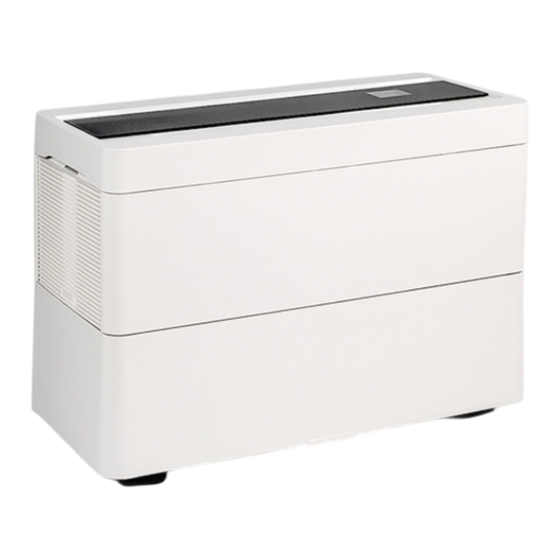
1. The B 600 evaporative humidifier 1.1 General overview Filling opening (under glass plate) Air outlet Touch display (under glass plate) Air inlet opening Water tank Fig. 1.1.1: Evaporative humidifier B 600 Scope of Fig. 1.1.2: Scope of Pos. Number Designation Fig. -
Page 5: Touchdisplay
Fig. 1.3.1: Radio humidity 1.4 Functional description The B 600 humidifier works according to the natural principle of evaporation. A water pump continuously conveys water from the water tank (3) into the oval water channel (2). -
Page 6: Security
2. Security This section provides an overview of all important safety aspects for the protection of persons and for safe and trouble-free operation. Further task-related safety instructions are contained in the sections on the individual life phases. 2.1 Symbols in this manual Safety instructions Safety instructions in this manual are marked by symbols. -
Page 7: Intended Use
2.2 Intended Use The B 600 Professional evaporative humidifier is intended exclusively for humidifying room air in private and professional environments. Not intended for use in medical facilities! Intended use also includes compliance with all the information in these instructions. -
Page 8: Symbols On The Unit
2.3 Symbols on the device The following symbols and information signs are attached to the unit. They refer to the immediate environment in which they are applied. WARNING! Danger if signage is illegible! Over time, stickers and signs can become dirty or otherwise unrecognisable, so that hazards cannot be recognised and necessary operating instructions cannot be followed. - Page 9 Children WARNING! Risk of injury for children! Children cannot assess the dangers when handling the humidifier. This can lead to serious injuries. Batteries and other small parts can be swallowed. Insert batteries immediately after receiving the humidifier or keep them out of reach of children.
-
Page 10: Responsibility Of The Operator
Wrong choice of NOTE! Risk of material damage due to incorrect placement of the humidifier! If the humidifier is operated on floors that are not moisture-resistant, there is a risk of damaging them. Only place the humidifier on moisture-resistant floors. A safety drip tray to protect against leaking water (... -
Page 11: Environmental Protection
Sanitation specialist The sanitation specialist is trained and certified for the specific task area in which he/she works and knows the applicable standards and re- gulations. Due to their professional training and experience, sanitary specialists are able to carry out work on all sanitary installations and to independently recognise and avoid possible hazards. -
Page 12: Transport And Storage
3. Transport and Storage 3.1 Safety instructions for transport and storage Improper transport NOTE! Material damage due to improper transport! In case of improper transport, transport pieces can fall or topple over. This can cause considerable damage to property. When unloading the transport pieces on delivery, proceed carefully and observe the symbols and instructions on the ... -
Page 13: Storage When Not In Use
3.5 Storage wh en not in u se If the humidifier is taken out of operation for a longer period of time, proceed as follows: Personnel: Operator 1. Empty and clean the water tank ( „6.3.3 Cleaning the water tank" on page 33). ... -
Page 14: Commissioning
4. Commissioning 4.1 Safety instructions for initial commissioning DANGER! Danger to life due to commissioning of a defective unit! Starting up a defective unit can lead to life-threatening situations and cause considerable damage to property. • Never operate a defective unit. •... - Page 15 Putting the radio humidity transmitter Staff: Operator 1. Carefully lift the cover of the radio humidity transmitter with a small screwdriver and remove it. Fig. 4.3.3: Opening the cover 2. Insert the appropriate batteries as shown in the illustration (1). The plus and minus poles are marked on both the circuit board and the batteries.
- Page 16 2. Open the main menu and select the menu item "FAN" on Fig. 4.3.6: Switching on the humidifier page 2 NOTE! entry of new values (fan speed, target humidity, etc.) must always be confirmed with Fig. 4.3.7: B 600 Start menu...
-
Page 17: Operating The Humidifier
5. Operating the humidifier This chapter only describes the operation of the standard version of the humidifier. For the operation of accessories, see chapter "8. Accessories" on page 44. 5.1 Displays on the Display of the fan speed The speed of the fan can be adjusted in eight steps. In addition, the unit has an automatic function. - Page 18 Display current room temperature The unit has a display of the current room temperature. Fig. 5.1.4: Display room temperature Display water change The unit has a water change interval display. The interval can be individually adjus- ted to the conditions on site in the main menu under the menu item "SER- VICE"...
-
Page 19: Switching On And Off
Display notes and error messages In the lower area of the touch display you will find a white field. Possible warning messages or notes are displayed here. For an overview of the various messages, see chapter "7.2 Fault indication" on page 37. -
Page 20: Filling The Water Tank
5.3 Filling the water tank Improper filling DANGER! NOTE! Danger of electric shock if filled im- Risk of material damage if filled incorrectly! properly! Incorrect filling of the water tank can lead to faults in the water level Improper filling can result in serious or indicator or to defects in the appliance. -
Page 21: Setting The Fan Speed
5.5 Setting the blower level Staff: Operator 1. Open the settings menu. 2. The fan speed is controlled via the buttons The speed of the fan can be adjusted in eight steps. In addition, the unit has an automatic function. - Page 22 Encode radio humidity transmitter Staff: Operator 1. Carefully lift the cover of the radio humidity transmitter with a small screwdriver and remove it. NOTE! The electronics of the radio humidity transmitter are very sensitive. Take care not to touch the elec- tronics or damage any components.
-
Page 23: Change Menu Settings
5.7 Change menu settings The unit offers the possibility of making various settings according to one's own wishes, deviating from the factory settings. The visual repre- sentation of the menu is done via the touch display. To change the menu setting, proceed as follows: Staff: ... - Page 24 Setting Comment Main menu Operating Setting the operating mode Humidifier/Air Purifier The B 600 can be used mode both as a humidifier and as an air purifier. Fixed value/timer In addition to normal operation, the B 600 can also be operated via an integrated timer.
-
Page 25: Operating Modes
5.8 Operating modes You have the option of operating the unit as a humidifier or air purifier. The units are delivered from the factory in humidifier mode. In air purifier mode, the unit is operated without water. The fan always runs, but the water pump is deactivated. 5.8.1 Air purifier mode NOTE! Possible contamination of the unit and working environment du-... -
Page 26: Operating Modes Fixed Value & Timer
5.8.3 Operating modes fixed value & timer The B 600 offers you the option of controlling the humidification over time. In the factory setting, the unit is set to the desired target humidity value in fixed value mode and thus maintains the humidity in the desired humidity range. -
Page 27: Cleaning Schedule
6.2 Cleaning schedule Interval * Maintenance work Staff daily Check the water level. The appliance switches off automatically at a residual water level of approx. 15 Operator litres (4 gallons) (not applicable with automatic water supply). Check the humidity value via the display on the control panel. Operator weekly Change the water and rinse the tank well. - Page 28 5. Open the side cover. 6. Remove the cable grommet on the back of the unit and thread the pow- er cable through the opening in the housing. Î If necessary, disconnect the connections for the automatic water supply Fig.
-
Page 29: Change Filter
6.3.2 Change filter Replacement evaporative filters can be ordered from your local specialist dealer. 6.3.2.1 Change evaporation Order number: 1603: BIO filter B 500 (pack of 2) 1601: Foam filter B 500 Remove old filter WARNUNG! Gefahr durch Stromschlag bei nicht gezogenem Netzstecker! Staff: ... - Page 30 Insert new filter 5. Insert the new filter and fix it along the water distribution. 6. Fix the filter on both sides to the fastening hooks (1). Fig. 6.3.2.4: Fixing the filter 7. Check that the filter is firmly seated in the water distribution rail and that no fibres are protruding.
-
Page 31: Change Cleaning Filter
In addition to the evaporation filter or activated charcoal cleaning Order number (by operating mode): Fine dust filter, the B 600 humidifier has a coarse dust filter and a cleaning filter filter set F7 (humidifier): 1620 Hepa filter set (air... -
Page 32: Insert Activated Carbon Cleaning Filter
7. Check that the filter is seated in the water distribution rail. 8. Replace the clamping bracket (2) on both sides. 9. Replace the upper part of the humidifier housing. Fig. 6.3.2.3.3: B 600 with activated carbon cleaning filter NOTE! -
Page 33: Cleaning The Water Tank
6.3.3 Cleaning the water WARNING! Danger of electric shock if the mains plug is not pulled out! Staff: Operator Protective equipment: Chemical-resistant protective gloves Safety googles Materials:: Limescale remover 1. Switch off the humidifier and disconnect the mains plug. Turn off the water supply, if appl icable. -
Page 34: Descale Appliance
Gefahr durch Stromschlag • To achieve an optimal result, the use of the limescale remover (order number: nicht gezogenem 9016) from BRUNE is recommended. Netzstecker! • Place the appliance on a suitable non-sensitive surface for descaling. Staff: Operator Protective equipment: ... - Page 35 4. Open the side cover. 5. Remove the cable gland (1) on the back of the unit and thread the power cable through the opening in the housing. Î If necessary, disconnect the connections for the automatic water sup- ply (2) and flushing device (3).
- Page 36 Dirt and limescale often also settle in the pump body around the pump blade, which means that the pump can no longer develop its full performance. We therefore recommend cleaning the inside of the pump body as well. 12. Use a small slotted screwdriver to prise open the pump cover at the notch (1).
-
Page 37: Recognising And Remedying Faults
Î For all other problems, contact the manufacturer. 7.2 Fault indication The B 600 Professional evaporative humidifier has an independent monitoring system that makes it possible to quickly and reliably detect faults and react accordingly. If there is a fault, it is indicated via the fault message display on the touch display. - Page 38 Error display The following table shows the problems that may occur and the corresponding solutions to the problem. Error display Remedy Staff Water tank empty. Check the water level. Fill the water tank if necessary ( chapter '5.3 Filling the water Operator ...
-
Page 39: Error Table
7.3 Error table If there is no error and the unit still does not work properly, check the following points: Error description Cause Remedy Staff No function, humidifier Unit not switched on. Operator Switch on the unit chapter "5.2 Switching on and off" on does not start. -
Page 40: Troubleshoot
7.4 Correct error 7.4.1 Replace pump A new pump can be ordered from your local dea- ler (order no. 1521). Remove old pump WARNING! Danger of electric shock if the mains plug is not pulled out! Staff: Operator 1. Switch off the humidifier and disconnect the mains plug. Turn off the water supply, if any. - Page 41 8. Pull off the pump hoses. Fig. 7.4.1.5: Pulling off the pump hoses 9. loosen the water pump in the direction of the arrow to the right and pull it out carefully. Fig. 7.4.1.6: Loosening the water pump ...
-
Page 42: Replace Blower
14. Reattach the pump hoses. Make sure that the pump hoses are tight. Otherwise there is a risk of water leaking out. Fig. 7.4.1.9: Attach pump hoses 15. Place the centre section in the water tank. 16. Thread the power cable through the opening in the housing and attach the cable grommet. - Page 43 5. Lift the centre section out of the water tank and place it to the side. Fig. 7.4.2.3: Remove centre part 6. Loosen the fan plug by pressing the plug clips and pull it out (1). Fig. 7.4.2.4: Loosening the fan plug ...
-
Page 44: Accessories
The use of incorrect or faulty accessories can be dangerous manufacturer. In this case, contact the manufacturer. for the user and cause damage, malfunctions or total failure. Only use original accessories from BRUNE Luftbe- feuchtung Proklima GmbH or accessories approved by the manufacturer. -
Page 45: Uv Disinfection And Lime Conversion Cartridge Cleaning
8.1.1 UV disinfection and lime conversion cartridge cleaning WARNING! UV disinfection clean Danger of electric shock if the mains plug is not pulled out! Staff: Operator Protective equipment: Chemical-resistant protective gloves Safety goggles Materials: Limescale remover ... - Page 46 8. Pull the pump hoses off the stainless steel pipe and clean them with the cleaning brush. Replace the pump hoses if they are very dirty or worn. Fig. 8.1.1.5: Cleaning the pump hoses 9. Remove the plastic Y-piece (1) from the stainless steel pipe and clean it carefully with the cleaning brush.
-
Page 47: Replace Uv Lamp
8.1.2 Replace UV lamp WARNING! Health hazard due to toxic mercury vapour! The UV lamp is located under the centre plate next to the pump The tube of the UV lamp contains toxic mercury. If motor. To replace it, proceed as follows: the mercury vapours are inhaled, there is an acute danger of poisoning. - Page 48 6. Disconnect the tubes from the UV lamp housing. 7. Remove the earth cable (2). Fig. 8.1.2.4: Disconnect connections 8. Remove the metal housing around the UV lamp. To do this, turn the metal tube anticlockwise. Then carefully pull off the housing. WARNING! If the UV lamp inside the stainless steel tube is da- maged, toxic mercury vapours may escape!
-
Page 49: Automatic Water Supply
8.2 Automatic Water supply Connecting the humidifier to the local water supply eliminates the need for Order numbers: 1800 manual filling. Refilling is done by an electronically controlled solenoid valve. This automatically opens the water supply when a minimum water level is Requirements reached and stops it as soon as the water tank is full. -
Page 50: Automatic Flushing Device
8.3 Automatic Flushing device Order number: 1850 The automatic rinsing device is used to replace the residual water Requirements in the water tank at regular intervals and to add fresh water. It is Automatic water supply only possible in combination with the automatic water supply; The installation of the automatic flushing device ... -
Page 51: Safety Catch Basin
8.4 Safety catch basin The safety collection tray (1) is placed below the evaporative humidifier B 600. It catches the excess water in the event of a water leak. Order number: 1820 Fig. 8.4.1: Safety catch basin 8.5 Safety water sensor... -
Page 52: Water Fresh
For order numbers, see malfunctions or total failure. chapter "Appendix" on page 55. Only use original spare parts from BRUNE Luftbefeuchtung Proklima GmbH or spare parts approved by BRUNE Luftbefeuchtung Proklima GmbH. If you are unsure, always contact our service ... -
Page 53: Filter Overview
9.1 Filter overview Various evaporation and cleaning filters are available for the B 600. Designation Order number BIO evaporation filter 1603 Foam evaporation filter 1601 Activated carbon cleaning filter 1625 Fine dust filter set F7 (humidifier) 1620 Hepa Filter Set H10 (air purifier) 1619 10. -
Page 54: Operating Conditions
°C / °F Relative humidity 30 - 90 11.4 Nameplate The type plate is located under the upper part of the housing above the mains connection and contains the following informa- tion: BRUNE B 600 0822 Manufacturer Type max. 130 Series ... - Page 55 1601 Foam filter B 500 / B 600 1603 Bio-Filter B 500 / B 600 1620 Fine dust filter set F7 B 600 (humidifier) 1619 Hepa Filter Set H10 B 600 (air purifier) 1625 Activated carbon cleaning filter B 600...
- Page 56 H u m i d i t y S y s t e m s - s i n c e 1 9 2 8 Luftbefeuchtung Proklima GmbH Schwarzacher Str. 13 74858 Aglasterhausen Germany Phone.: +49 (0) 6262 / 5454 Fax: +49 (0) 6262 / 3255 Mail: mail@brune.info Web: www.brune.info...
Need help?
Do you have a question about the B 600 and is the answer not in the manual?
Questions and answers