Table of Contents
Advertisement
Quick Links
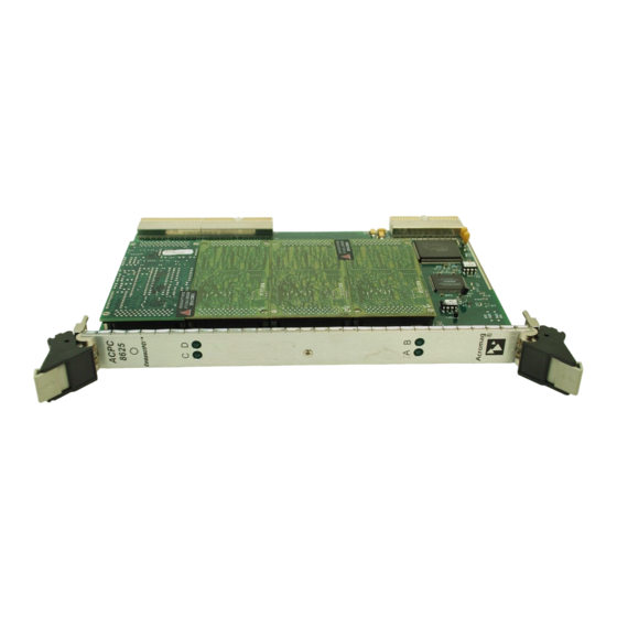
Series IP320 Industrial I/O Pack
12-Bit High Density Analog Input Board
r e t i r e d
USER'S MANUAL
ACROMAG INCORPORATED
30765 South Wixom Road
P.O. BOX 437
Wixom, MI 48393-7037 U.S.A.
Tel: (248) 624-1541
Fax: (248) 624-9234
Copyright 1994, Acromag, Inc., Printed in the USA.
Data and specifications are subject to change without notice.
8500-484-F00J005
Advertisement
Table of Contents

Subscribe to Our Youtube Channel
Summary of Contents for Acromag IP320 Series
- Page 1 USER’S MANUAL ACROMAG INCORPORATED 30765 South Wixom Road P.O. BOX 437 Wixom, MI 48393-7037 U.S.A. Tel: (248) 624-1541 Fax: (248) 624-9234 Copyright 1994, Acromag, Inc., Printed in the USA. Data and specifications are subject to change without notice. 8500-484-F00J005...
-
Page 2: Table Of Contents
The information contained in this manual is subject to change DRAWINGS Page without notice. Acromag, Inc. makes no warranty of any kind with 4501-433 IP320 JUMPER LOCATIONS......regard to this material, including, but not limited to, the implied 4501-434 IP MECHANICAL ASSEMBLY...... -
Page 3: Industrial I/O Pack Interface Features
For repairs to a product damaged in shipment, refer to the • Wait/Hold State Support - This IP module supports both Acromag Service Policy to obtain return instructions. It is “wait” states (generated by the IP module) and “Hold” states suggested that salvageable shipping cartons and packing material be saved for future use in the event the product must be shipped. -
Page 4: Default Hardware Jumper Configuration
SERIES IP320 INDUSTRIAL I/O PACK 12-BIT HIGH DENSITY ANALOG INPUT BOARD ___________________________________________________________________________________________ Default Hardware Jumper Configuration Analog Input Data Format A board shipped from the factory is configured as follows: The analog input data will appear as Unipolar Straight Binary (USB) for unipolar input ranges (e.g. -
Page 5: Analog Input Noise And Grounding Considerations
+ and - input leads). high level of accuracy/resolution is needed (12-bits or more). Contact your Acromag representative for information on our many Table 2.5: IP320 Field I/O Pin Connections (P2) isolated signal conditioning products that could be used to interface to the IP320 input module. -
Page 6: Programming Information
I/O space. All accesses are performed on a 16-bit word basis (D0..D15). Table 3.1: IP320 I/O Space Address Memory Map Base Even Byte Odd Byte Acromag ID Code Address + IP Model Code (Hex) Not Used (Revision) R/W - Control Register... -
Page 7: Adc Convert Command
SERIES IP320 INDUSTRIAL I/O PACK 12-BIT HIGH DENSITY ANALOG INPUT BOARD ___________________________________________________________________________________________ Mode Mode ODD Byte HIGH Desired Chan. GSEL GSEL used HIGH RESET CONDITION: all bits are undefined. Registers should be programmed to the desired configuration before starting ADC analog input acquisition. -
Page 8: Read Adc Data
Software calibration uses some fairly complex equations. 3. Execute the ADC Convert command. Acromag provides you with the Industrial I/O Pack Software Library 4. Write to the control register to configure the acquisition mode, diskette to make communication with the board and calibration easy. -
Page 9: Uncalibrated Performance
SERIES IP320 INDUSTRIAL I/O PACK 12-BIT HIGH DENSITY ANALOG INPUT BOARD ___________________________________________________________________________________________ Uncalibrated Performance Ideal Maximum Maximum Calibration Value Tolerance Temperature @25 o C (Volts) Drift (ppm/ o C) The uncalibrated performance is affected by two primary error Signal (Volts) sources. - Page 10 SERIES IP320 INDUSTRIAL I/O PACK 12-BIT HIGH DENSITY ANALOG INPUT BOARD ___________________________________________________________________________________________ m = Gain * (Volt CALHI - Volt CALLO ) / (Count CALHI - 1. To prepare to measure Count CALLO , write to the Control Count CALLO ) Register (@Base + 00H) to setup the auto zero acquisition mode and PGA gain = 1 by writing 0300H.
-
Page 11: Theory Of Operation
SERIES IP320 INDUSTRIAL I/O PACK 12-BIT HIGH DENSITY ANALOG INPUT BOARD ___________________________________________________________________________________________ Table 3.6: Maximum Overall Calibrated Error @25° ° ° ° C 1. To prepare to measure Count CALLO , write to the Control Register (@Base + 00H) to setup the CAL3 acquisition mode Input Range ADC Range Max Error... -
Page 12: Logic Interface
Please refer to Acromag's Service Policy Bulletin or contact ADC (-5 to +5, -10 to +10, or 0 to +10 Volts) as detailed in Section Acromag for complete details on how to obtain parts and repair. 2. Jumper selection should be made prior to powering the unit. -
Page 13: Industrial I/O Pack Compliance
SERIES IP320 INDUSTRIAL I/O PACK 12-BIT HIGH DENSITY ANALOG INPUT BOARD ___________________________________________________________________________________________ Input Overvoltage Protection..±32 Volts with power applied, Notes: ±20 Volts unpowered. 2. Range assumes the programmable gain is equal to one. Additional ranges are created with other gains. Divide the listed Input Resistance......1000 MΩ, Typical. -
Page 14: Appendix
(per MIL-G-45204, Type II, Grade C). Cable: 50-wire flat ribbon cable, 28 gage. Non-Shielded cable Connects to Acromag termination panel 5025-552 from the rear model uses Acromag Part 2002-211 (3M Type C3365/50 or of the card cage, or to AVME9630/9660 boards within card equivalent). -
Page 15: 4501-433 Ip320 Jumper Locations
SERIES IP320 INDUSTRIAL I/O PACK 12-BIT HIGH DENSITY ANALOG INPUT BOARD ___________________________________________________________________________________________ - 15 -... -
Page 16: 4501-435 Analog Input Connection Diagram
SERIES IP320 INDUSTRIAL I/O PACK 12-BIT HIGH DENSITY ANALOG INPUT BOARD ___________________________________________________________________________________________ - 16 -... -
Page 17: 4501-462 Cable 5025-550 (Non-Shielded)
SERIES IP320 INDUSTRIAL I/O PACK 12-BIT HIGH DENSITY ANALOG INPUT BOARD ___________________________________________________________________________________________ - 17 -... -
Page 18: 4501-464 Termination Panel 5025-552
SERIES IP320 INDUSTRIAL I/O PACK 12-BIT HIGH DENSITY ANALOG INPUT BOARD ___________________________________________________________________________________________ - 18 -...


Need help?
Do you have a question about the IP320 Series and is the answer not in the manual?
Questions and answers