Table of Contents
Advertisement
Quick Links
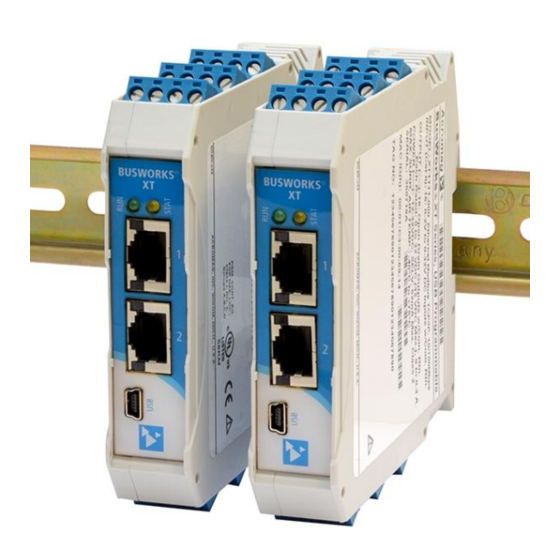
BusWorks® XT Series for Modbus TCP/IP
USB Programmable
10/100MB Industrial Ethernet I/O Modules
Model XT1231-000 & XT1241-000
16-Channel Single-Ended Current Input
16-Channel Single-Ended Voltage Input
USER'S MANUAL
ACROMAG INCORPORATED
Tel: (248) 295-0880
30765 South Wixom Road
Fax: (248) 624-9234
Wixom, MI 48393-2417 U.S.A.
email: sales@acromag.com
Copyright 2013, Acromag, Inc., Printed in the USA.
8500952G
Data and specifications are subject to change without notice.
Advertisement
Table of Contents

Subscribe to Our Youtube Channel
Related Manuals for Acromag BusWorks XT1231-000


Summary of Contents for Acromag BusWorks XT1231-000
- Page 1 16-Channel Single-Ended Voltage Input USER’S MANUAL ACROMAG INCORPORATED Tel: (248) 295-0880 30765 South Wixom Road Fax: (248) 624-9234 Wixom, MI 48393-2417 U.S.A. email: sales@acromag.com Copyright 2013, Acromag, Inc., Printed in the USA. 8500952G Data and specifications are subject to change without notice.
-
Page 2: Table Of Contents
MODBUS REGISTERS ..................32 Register Functions ......................33 Data Types ......................... 34 Register Map ........................35 TROUBLESHOOTING ..................36 Diagnostics Table ....................... 36 Service & Repair Assistance ....................39 Acromag, Inc. Tel: 248-295-0880 - 2 - - 2 - http://www.acromag.com http://www.acromag.com... - Page 3 This is very important where property loss or human life is involved. It is important that you perform satisfactory overall system design and it is agreed between you and Acromag, that this is your responsibility.
-
Page 4: Getting Started Description
DIN rail. Units are conveniently setup and configured for network operation via a USB connection to a host computer running Acromag configuration software. These models will interface with any mix of up to 16 Single-Ended current inputs (Model XT1231-000),... -
Page 5: Mechanical Dimensions
DIN rail spring clip down while pulling the bottom of the module outward until it disengages from the rail. Tilt it upward to lift it from the rail. Acromag, Inc. Tel: 248-295-0880 - 5 - - 5 - http://www.acromag.com... -
Page 6: Electrical Connections
As a rule, input wires are normally separated from power and network wiring for safety and isolation, as well as for low noise pickup. Acromag, Inc. Tel: 248-295-0880 - 6 - - 6 - http://www.acromag.com... -
Page 7: Power Connections
TO THE UNIT MAY RESULT. NOTE: IT IS RECOMMENDED THAT SUPPLIES CAPABLE OF DELIVERING MORE THAN 2.5A TO THE BUS BE FUSED WITH A HIGH SURGE TOLERANT FUSE. Acromag, Inc. Tel: 248-295-0880 - 7 - - 7 - http://www.acromag.com http://www.acromag.com... -
Page 8: Usb Connection
Important – End Stops: If this module uses the optionally powered (or redundantly powered) via the DIN rail bus for hazardous location installations (Class I, Division 2 or ATEX Zone 2) it must use two end stops (Acromag 1027-222) to secure the terminal block and module (not shown). -
Page 9: Input Connections
(i.e. each input with respect to a common return connection). The XT1231-000 model has 16 Single-Ended DC current inputs, while the XT1241-000 model has 16 Single-Ended DC voltage inputs. An optional current sensor (Acromag model 5020-350) may be used with the XT1231-000 to additionally monitor AC currents. - Page 10 Refer to the following figures for example DC current input connections to the XT1231-000 model. Acromag, Inc. Tel: 248-295-0880 - 10 - - 10 - http://www.acromag.com...
- Page 11 Refer to the following figures for example DC voltage input connections. Acromag, Inc. Tel: 248-295-0880 - 11 - - 11 - http://www.acromag.com...
-
Page 12: Analog Return Ground Connection
These are also helpful for cables connected to Host USB and Ethernet as well. Use Laird 28A2029-0A2 or similar for I/O & Power (Acromag 4001-135), Laird 28A0807-0A2 or similar for Ethernet (Acromag 4001-139), and Laird 28A0350-0B2 or similar for USB cables (Acromag 4001-140). -
Page 13: Earth Ground Connections
USB software is contained in a zip file that can be downloaded free of charge from our web site at www.acromag.com. Look for the software zip file 9500465 (XT install shield shell program) in the Documents and Downloads page for your XT product. - Page 14 Start/Stop polling the input channels. For a more detailed configuration procedure, see Configuration • Step-by-Step of the Technical Reference on page 16. Display the current reading of the inputs. Acromag, Inc. Tel: 248-295-0880 - 14 - - 14 - http://www.acromag.com http://www.acromag.com...
- Page 15 For a more detailed configuration procedure, see Configuration Step-by-Step of the Technical Reference on page 16. Acromag, Inc. Tel: 248-295-0880 - 15 - - 15 - http://www.acromag.com http://www.acromag.com...
-
Page 16: Technical Reference
IP address setting, or having to change the address setting of your network card to an address in the module’s subnet address domain in order to talk to it. Acromag, Inc. Tel: 248-295-0880 - 16 - - 16 - http://www.acromag.com... -
Page 17: Device/Communication Setup
Note that you should already have power connected to the XT123/XT124 at this point, as this model does not utilize USB power and you will not be able to configure, calibrate, or test the unit without also having power applied. After executing the Acromag Configuration software for this The Device/Communication Setup screen is split into model, the screen shown below will appear, if you have not 2 parts: Device Select &... - Page 18 (address domain) of the primary gateway. first Domain Name Server used on this network. The DNS 2 Address refers to the IP address of the secondary Domain Name Server used on this network. Acromag, Inc. Tel: 248-295-0880 - 18 - - 18 - http://www.acromag.com http://www.acromag.com...
- Page 19 You can click the [Exit] button in the lower right hand part of this screen to exit the Configuration Software, or simply click on another tab to access another page before exiting this software. Acromag, Inc. Tel: 248-295-0880 - 19 - - 19 - http://www.acromag.com...
-
Page 20: I/O Configuration/Test
This is not used by the firmware or software and just serves as a convenient label for discerning the input function or its application over USB. Acromag, Inc. Tel: 248-295-0880 - 20 - - 20 - http://www.acromag.com... - Page 21 TIP: Be sure to Stop polling a module before moving onto another page. Note that you will always have to restart polling if you come back to this page and want to poll the inputs. Acromag, Inc. Tel: 248-295-0880 - 21 - - 21 - http://www.acromag.com...
- Page 22 For current input models, this will be 11.17mA or 20mA, depending on the input range. Once you input full-scale precisely, click the [OK] button and follow the on-screen prompts to complete full-scale calibration. Acromag, Inc. Tel: 248-295-0880 - 22 - - 22 - http://www.acromag.com http://www.acromag.com...
- Page 23 “Timeout Error” during calibration. If you encounter a Transfer or Timeout Error, you may have to repeat the calibration process. Additionally, it may be necessary to reboot this software. Acromag, Inc. Tel: 248-295-0880 - 23 - - 23 - http://www.acromag.com http://www.acromag.com...
-
Page 24: I2O Mapping Page
It IMPORTANT: i2o refers to an Acromag proprietary method of still works if the target output module comes online input-to-output communication, done over the network, without after the input module, but may take several other hard-wired connections between inputs and outputs. - Page 25 Note: It is not recommended to specify percent change without also specifying an update interval, as this can make successive i2o trigger levels vary widely. Acromag, Inc. Tel: 248-295-0880 - 25 - - 25 - http://www.acromag.com...
- Page 26 8 channels and then click the [Send i2o Config] button one time to write your entire i2o configuration. See the Status field for the status of this operation over USB. Acromag, Inc. Tel: 248-295-0880 - 26 - - 26 - http://www.acromag.com...
-
Page 27: Network Home Page
USB connection to the device (scroll down this page to see all the communication parameter settings). Acromag, Inc. Tel: 248-295-0880 - 27 - - 27 - http://www.acromag.com http://www.acromag.com... -
Page 28: Block Diagram
USB signals be isolated when connected to a PC to prevent a ground loop from occurring between the PC earth ground and a grounded input return, which could have a negative effect on the input measurement for severe ground loop currents. Acromag, Inc. Tel: 248-295-0880 - 28 - - 28 - http://www.acromag.com... -
Page 29: About Modbus Tcp/Ip
(Ethernet), with a networking standard (TCP/IP), and a standard method of representing data (Modbus). Then, a Modbus TCP/IP message is simply a Modbus communication encapsulated in an Ethernet TCP/IP wrapper. Acromag, Inc. Tel: 248-295-0880 - 29 - - 29 - http://www.acromag.com... -
Page 30: Ip Addressing
TIP: The first node (0), node 10, and the last node (255 for our example) are typically reserved for servers and may yield poor results if used. Acromag, Inc. Tel: 248-295-0880 - 30 - - 30 - http://www.acromag.com... -
Page 31: Dynamic Host Configuration Protocol (Dhcp)
IP addresses. These servers contain information on some segment of the domain name space and make this information available to clients called resolvers. For example, the DNS allows us to use “Acromag.com” as an IP address rather than a complicated number string. -
Page 32: Modbus Registers
Holding registers contain read/write information that may be configuration data or output data. For example, the high limit value of an alarm function operating at an input, or an output value for an output channel. Acromag, Inc. Tel: 248-295-0880 - 32 - - 32 - http://www.acromag.com... -
Page 33: Register Functions
03 (Illegal Data Value) will be returned in the response message. You may refer to the Modbus specification for a complete list of possible error codes. Note that register mirroring used in some earlier Acromag models is not supported by Series XT models. Acromag, Inc. Tel: 248-295-0880... -
Page 34: Data Types
30 30 30 2C 39 33 30 30 2D 32 32 31 30 31 32 33 34 35 41 2C 30 31 32 33 34 35 (“ACROMAG,XT1231-000, 9300-221 7 byte serial number&rev,six-byteMAC ID”) Note: The XT1231-000 slave ID is “36” and the firmware number is 9300-221. The XT1241-000 slave ID is “37”... -
Page 35: Register Map
This register counts from 0 to 65535 and wraps back around to 0. Acromag, Inc. Tel: 248-295-0880 - 35 - - 35 - http://www.acromag.com http://www.acromag.com... -
Page 36: Troubleshooting
Acromag’s Application Engineers a good network connection and proper can provide further technical power voltage. Return module to Acromag assistance if required. Repair for repair/reprogramming. services are also available from Unit Fails to Start-up or Initialize…... - Page 37 USB Software Fails to Detect Module… Bad USB Connection Recheck USB Cable Connection USB has not enumerated the Use the reset button on the Acromag USB device. isolator to trigger renumeration of the module, or simply unplug and replug the USB cable to the module.
- Page 38 This ensures subsequent i2o triggers occur at every interval of update time and percent driven triggers are calculated from a steady level between timed updates. Acromag, Inc. Tel: 248-295-0880 - 38 - - 38 - http://www.acromag.com http://www.acromag.com...
-
Page 39: Service & Repair Assistance
Acromag for repair or replacement. Acromag has automated test equipment that thoroughly checks and calibrates the performance of each module, and can restore firmware. Please refer to Acromag’s Service Policy and Warranty Bulletins, or contact Acromag for complete details on how to obtain repair or replacement. -
Page 40: Accessories
Ethernet Patch Cable, 3 feet long, Model 5035-369 Ethernet Patch Cable, 15 feet long, Model 5035-370 This cable is used to connect a module to your network switch (like an Acromag 900EN-S005 or equivalent Ethernet switch), and is double-shielded for lower emissions and increased RFI resistance. -
Page 41: Specifications
XT1231 units utilize the ±1.325V A/D range with ±20mA DC driving ±0.548V full-scale to the A/D. An optional external sensor is required to monitor AC current signals (Acromag Model 5020-350). The AC sensor drives 0 to 11.17mA DC to the module (see Table 1 below for scaling to AC current). - Page 42 0 to 2A AC “ 0 to 1A AC “ AC Input Burden: A function of the wire gauge resistance used for primary turns (the current carrying wire being monitored). Acromag, Inc. Tel: 248-295-0880 - 42 - - 42 - http://www.acromag.com http://www.acromag.com...
- Page 43 12.1K/100.6K resistive voltage divider (0.12028x). All input ranges are normalized to ±30000 for ±100%, and 0-30000 for 0-100% (or ±20000 for ±100%, and 0-20000 for 0-100% with legacy support enabled). Acromag, Inc. Tel: 248-295-0880 - 43 - - 43 - http://www.acromag.com...
-
Page 44: Power
CAUTION: Terminal voltage at or above 12V minimum must be maintained to the unit during operation. Do not exceed 36VDC peak to avoid damage to the unit. Power Supply Effect: Less than 0.001% of output span effect per volt DC change. Acromag, Inc. Tel: 248-295-0880 - 44 - - 44 - http://www.acromag.com... -
Page 45: Usb Interface
TCP/IP. The unit includes a built-in web page for ID on the network using a standard web-browser, but configuration of the unit is only possible using configuration software running on a Windows PC and connected via USB. Acromag, Inc. Tel: 248-295-0880 - 45 - - 45 - http://www.acromag.com... -
Page 46: Enclosure & Physical
Acromag Application Note 8500-734 for example instructions on how to change the IP address of your PC network interface card in order to talk to an Acromag module. For this model, it is easier to use a USB connection to a host computer running the Configuration Software to change the IP address setting of the module to an address in the address domain of your network interface card. -
Page 47: Environmental
The use of low EMI double-shielded Ethernet cable is also helpful in curbing emissions. Acromag, Inc. Tel: 248-295-0880 - 47 - - 47 - http://www.acromag.com... -
Page 48: Agency Approvals
Its behavior as a 16 Channel analog input module is determined via a temporary USB connection to a host computer or laptop running a Windows-compatible configuration software program specific to Acromag, Inc. Tel: 248-295-0880 - 48 - - 48 - http://www.acromag.com... -
Page 49: Revision History
REVISION HISTORY Release Date Version EGR/DOC Description of Revision 15-APR-14 BC/KLK Initial Acromag “A” Release. 24-APR-14 BC/ARP Remove references to IEEE Floating Point numbers on page 34. 10-SEP-14 CAP/ARP Added UL Mark (removed pending, per ECO #14H030). 13-OCT-14 BC/CAP Added MTBF Data.
Need help?
Do you have a question about the BusWorks XT1231-000 and is the answer not in the manual?
Questions and answers