
Related Manuals for R&S EDST300


Summary of Contents for R&S EDST300
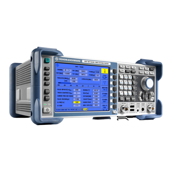
- Page 1 ® R&S EDST300 TACAN/DME Station Tester Getting Started (;ÝÆ_2) 1179564702 Version 01...
- Page 2 ® 1179.5647.02 | Version 01 | R&S EDST300 ® Throughout this manual, products from Rohde & Schwarz are indicated without the symbol , e.g. ® ® R&S EDST300 is indicated as R&S EDST300. R&S EDST-Bxy/-Kxy is indicated as R&S EDST-Bxy/-Kxy.
- Page 3 Target audience This document is aimed at installers, technicians and operators of the R&S EDST300. It assumes the readers are familiar with basic handling of electri- cal equipment and have knowledge of avionic navigation systems. Where do I find safety information? Safety information is part of the product documentation.
- Page 4 ® Safety and regulatory information R&S EDST300 Safety instructions sheet, manuals and the printed "Safety Instructions". If you are unsure about the appropriate use, contact Rohde & Schwarz customer service. Using the product requires specialists or specially trained personnel. These users also need sound knowledge of at least one of the languages in which the user interfaces and the product documentation are available.
- Page 5 ® Safety and regulatory information R&S EDST300 Safety instructions ● Only use intact cables and route them carefully so that they cannot be dam- aged. Also ensure that nobody can trip over loose cables. Handling batteries safely The product contains exchangeable or built-in lithium polymer or lithium ion cells or batteries.
- Page 6 ® Safety and regulatory information R&S EDST300 Labels on the product rier of this classification. Follow the carrier’s transport stipulations in line with IATA-DGR, IMDG-Code, ADR or RID. Using headphones Take the following measures to prevent hearing damage. Before using head- phones, check the volume and reduce it if necessary.
- Page 7 ® Safety and regulatory information R&S EDST300 Korea certification class A Warning messages in the documentation A warning message points out a risk or danger that you need to be aware of. The signal word indicates the severity of the safety hazard and how likely it will occur if you do not follow the safety precautions.
- Page 8 Further documents are available at: www.rohde-schwarz.com/product/EDST300 Getting Started manual Introduces the R&S EDST300 and describes how to set up and start working with the product. Includes basic operations and general information, e.g. safety instructions, etc. A printed version is delivered with the instrument.
- Page 9 ® Documentation overview R&S EDST300 The software makes use of several valuable open source software packages. An open-source acknowledgment document provides verbatim license texts of the used open source software. Application notes, application cards, white papers, etc. These documents deal with special applications or background information on particular topics.
- Page 10 (R&S EDST-K2 option). The modular design of the R&S EDST300 provides a high degree of flexibility to adapt it to the task at hand. An interrogator (R&S EDST-B2 option) with adjusta- ble output power (-80 dBm to +30 dBm peak power) is available for distance measurements.
- Page 11 ® Preparing for use R&S EDST300 Choosing the operating site Preparing for use Here, you can find basic information about setting up the product for the first time. Lifting and carrying The carrying handle on the side of the instrument is designed to lift or carry the instrument.
- Page 12 3 4.4.1 Placing the product on a bench top If you want to set up the R&S EDST300 on a benchtop or prepare the R&S EDST300 for mobile use, proceed as follows. To place the product on a bench top 1.
- Page 13 4.4.2 Mounting the R&S EDST300 in a rack If you use the product in a vehicle or in aircraft, install it in a rack provided for this purpose. Secure the product safely so that it cannot fall out and hurt passengers when the vehicle or aircraft is moving.
- Page 14 2. Lift the R&S EDST300 to shelf height. 3. Grab the handle and push the R&S EDST300 onto the shelf until the rack brackets fit closely to the rack. 4. Tighten all screws in the rack brackets with a tightening torque of 1.2 Nm to secure the R&S EDST300 in the rack.
- Page 15 Connecting to power To ensure high mobility and flexibility while using the R&S EDST300, it is equip- ped with an internal battery and a DC power supply connector on the rear panel of the instrument.
- Page 16 Chapter 5.1, "Front panel view", on page 20). If the interrogator option R&S EDST-B2 is installed on the R&S EDST300, the instrument can also provide HF output to a transmitter antenna via the "RF1 IN/ OUT" connector (see also Chapter 5.1.4.1, "Antenna connections RF1 IN/OUT and RF2 IN",...
- Page 17 To connect a transmit antenna ► Connect the transmit antenna to the "RF1 IN/OUT" on the front panel of the R&S EDST300. The R&S EDST300 transmitter antenna provides a maximum output of 20 W (43 dBm). 4.8.2 Connecting a suppressor line Using a bi-directional suppressor line, the instruments in an aircraft send signals to each other.
- Page 18 When the R&S EDST300 firmware is started, the TACAN functionality is copied from the stick to the RAM. After the R&S EDST300 is shut down, no TACAN func- tionality remains in the instrument. The TACAN stick cannot be used to store data; however, a second USB stick can be connected simultaneously for data logging.
- Page 19 Using the installed battery If the R&S EDST300 is powered using the internal battery and the batteries become empty, the instrument switches itself off. You cannot switch it back on until the DC power supply is connected.
-
Page 20: Keypad
EDST300 Front panel view Instrument tour Front panel view This chapter describes the front panel of the R&S EDST300, including all function keys and connectors. Figure 5-1: Front panel view of the R&S EDST300 Power key (ON / OFF switch) with status LEDs... - Page 21 R&S EDST300 user manual. Table 5-1: SYSTEM keys SYSTEM key Assigned functions [PRESET] Resets the instrument to the default state. [CAL] Starts a calibration on the R&S EDST300 [VOL] Volume control for audio output [SAVE] for future use [MEM] [LOCAL] Switches between remote and local operation of the R&S EDST300...
- Page 22 N-socket, 50Ω RF output with interrogator options If the R&S EDST300 is equipped with the interrogator option R&S EDST-B2, the "RF1 IN/OUT" connector can provide HF output to a transmitter antenna. The antenna has an equivalent frequency range and (peak) power range (1 W).
-
Page 23: Connector
5.1.4.4 Voltage supply for external consumers: 12 VDC OUT The R&S EDST300 provides a power supply for connected external devices at the 3-pole circular "12 VDC OUT" connector. The output for external consumers such as an active receiving antenna is supplied permanently with 12 VDC / 300... - Page 24 ® Instrument tour R&S EDST300 Front panel view 5.1.5 Navigation controls and general functions The navigation controls include a rotary knob and navigation keys. They allow you to navigate within the display or within dialog boxes. Rotary knob The rotary knob has several functions: ●...
- Page 25 Measurement keys Measurement keys provide access to the most common measurement settings and functions. A detailed description of the corresponding functions is provided in the R&S EDST300 user manual. Table 5-4: Measurement keys Measurement key Assigned functions Selects DME/TACAN measurement mode...
-
Page 26: Keys
® Instrument tour R&S EDST300 Front panel view 5.1.7 Keypad The keys in the data entry keypad are used to enter alphanumeric data and units. Data entry keys are only enabled while the cursor is placed on a data input field in a dialog. -
Page 27: Analog In Connector
Rear panel view Rear panel view This figure shows the rear panel view of the R&S EDST300. The individual ele- ments are described in more detail in the subsequent sections. The meanings of the labels on the product are described in Chapter 1.2, "Labels... - Page 28 Chapter 4.7, "Connecting to power", on page 15. 5.2.2 SUPPRESS IN / OUT connector The R&S EDST300 allows for a suppressor line signal to be input or output via the BNC "SUPPRESS IN / OUT" connector (see Chapter 4.8.2, "Connecting a suppressor line", on page 17).
-
Page 29: Trigger Input / Output
The "REF 10 MHz IN/OUT" connector can provide an external reference signal to the R&S EDST300, or from the R&S EDST300 to a connected device. In either case, the reference signal is at 10 MHz, with a power level of 1 V . - Page 30 5.2.8 LAN interface Use the "LAN" interface to connect the R&S EDST300 to a local network for remote control, printouts or data transfer. The data can be transferred with a rate of up to 1 Gbit per second. Configure the IP address and subnet mask in the gen- eral instrument settings.
- Page 31 EDST300 Device ID The serial number is used to define the default instrument name, which is: <Type><variant>-<serial_number> For example, EDST300-123456. The instrument name is required to establish a connection to the instrument in a LAN. Getting Started 1179.5647.02 ─ 01...
-
Page 32: Information
Understanding the display information Operating basics This chapter provides an overview on how to work with the R&S EDST300. It describes what kind of information is displayed on the screen and how to operate the R&S EDST300 via the front panel keys and other interaction methods. - Page 33 Which settings and results are displayed depends on the current measurement or instrument function. See the R&S EDST300 User Manual for details. Status bar The status bar at the bottom of the screen contains information on the operating status of the instrument and connected devices.
-
Page 34: Connector
Error and status messages). Accessing the functionality All functions available on the R&S EDST300 can be accessed using the keys on the front panel of the instrument. Some keys provide a softkey menu on the dis- play with further functions and settings. -
Page 35: Entering Data
® Operating basics R&S EDST300 Entering data Select the softkey for the setting or function as required. If necessary, select the "More softkeys" key to switch to the second softkey menu. The function is activated, or a new window is displayed to view or change spe- cific settings. - Page 36 Entering alphanumeric parameters If a field requires alphanumeric input, you can use the keypad on the front panel of the R&S EDST300. Every alphanumeric key represents several characters and one number. The decimal point key (.) represents special characters, and the sign key (-) toggles between capital and small letters.
- Page 37 ® Operating basics R&S EDST300 Entering data Correcting an entry 1. Using the arrow keys (see Chapter 5.1.5, "Navigation controls and general functions", on page 24), move the cursor to the right of the entry you want to delete. 2. Press the [BACK] key.
- Page 38 Mains The AC power adapter is currently supplying power to the R&S EDST300. Mount USB-Stick No USB storage device has been connected to the R&S EDST300 yet, for example for data logging. Can't mount The USB storage device connected to the R&S EDST300 could not be USB-Stick read correctly.
-
Page 39: Table Of Contents
® Index R&S EDST300 Index Keypad ..........26, 36 Key layout ........... 37 Alphanumeric parameters ....... 36 ANALOG IN Connector ........... 28 Labels on casing ........6 ANALOG OUT Connector ........... 28 Connector ........... 30 Application cards ........9 Application notes ........9 Arrow keys ..........24... - Page 40 ® Index R&S EDST300 Units Input ............ 26 Connector ........... 29 Warning messages ........7 White papers ..........9 Getting Started 1179.5647.02 ─ 01...
Need help?
Do you have a question about the EDST300 and is the answer not in the manual?
Questions and answers