Table of Contents
Advertisement
Quick Links
Advertisement
Chapters
Table of Contents

Related Manuals for R&S QAR50


Summary of Contents for R&S QAR50
- Page 1 ® R&S QAR50 Radome Tester User Manual (;Ýaê2) 1179499202 Version 02...
- Page 2 This document describes the following R&S QAR50 models and options: ● ® R&S QAR50 (1343.0099K02/03) ● ® R&S QAR50-K10 Frequency response measurements (1343.2091.02) ● ® R&S QAR50-K20 Phase mask measurements (1343.2110.02) ● ® R&S QAR50-K30 HD reflection image (1343.2133.02) ●...
-
Page 3: Table Of Contents
2 Documentation overview...............9 3 Welcome....................10 4 Preparing for use..................11 Choosing the operating site..................11 Unpacking and checking.................... 11 Installing the R&S QAR50..................14 Considerations for test setup..................19 Connecting the R&S QAR50..................20 Switching on or off......................21 Operating system......................21 5 Instrument tour..................23 System overview...................... - Page 4 ® Contents R&S QAR50 5.2.6 Device ID........................29 6 Test setup..................... 30 7 User interface..................34 8 Measurements and result displays............ 36 Normalization......................36 Measurement....................... 37 8.2.1 Reflection measurement....................38 8.2.2 Transmission measurement..................39 8.2.3 Phase measurement..................... 40 Result displays......................41 9 Configuration..................46 10 Data management................
-
Page 5: Safety And Regulatory Information
The product is heavy and must be installed and set up by trained staff. Always use appropriate lifting equipment when you lift or carry the product, like a forklift when the R&S QAR50 is still packed in its original box or a crane when it is unpacked. User Manual 1179.4992.02 ─ 02... - Page 6 Because of its weight, at least two strong people are required to move or install the R&S QAR50. During the installation, make sure that the installation site is only accessi- ble to people working on the installation.
-
Page 7: Labels On The Product
® Safety and regulatory information R&S QAR50 Labels on the product ● Only connect the product to a power source with a fuse protection of maximum 20 A. ● Ensure that you can disconnect the product from the power source at any time. -
Page 8: Warning Messages In The Documentation
® Safety and regulatory information R&S QAR50 Korea certification class A 1.3 Warning messages in the documentation A warning message points out a risk or danger that you need to be aware of. The sig- nal word indicates the severity of the safety hazard and how likely it will occur if you do not follow the safety precautions. -
Page 9: Documentation Overview
2 Documentation overview The user documentation for the R&S QAR50 consists of several documents. Getting started Introduces the R&S QAR50 and describes how to set up and start working with the product. A printed version is included in the delivery. User manual Contains a description of the R&S QAR50 system, including the features available in... -
Page 10: Welcome
QAR50 3 Welcome The R&S QAR50 is the ideal tool for accurately testing the quality of radomes and bumpers in the automotive radar frequency range at the end-of-line (EOL). It features sufficient space to easily accommodate bulky bumpers combined with spatially resolved measurements to evaluate the homogeneity of design emblems. -
Page 11: Preparing For Use
If class A equipment causes radio disturbances, take appropriate measures to eliminate them. 4.2 Unpacking and checking The R&S QAR50 is a large and heavy device. Unpacking, moving and installing the R&S QAR50 requires special arrangements. Follow the instructions provided here when you unpack the R&S QAR50. - Page 12 Carefully lift the R&S QAR50 out of the box. Lifting the R&S QAR50 out of the transport box Use a crane or similar lifting device to lift the R&S QAR50 out of its transport box. 1. Unpack the R&S QAR50 as described in Chapter 4.2, "Unpacking and...
- Page 13 Mount the harness legs at a maximum angle of 45° per eye bolt. < 45° Figure 4-2: Eye bolt load limit 4. Move the R&S QAR50 carefully to its operating site and put it firmly onto the ground. 5. Remove the lifting equipment.
-
Page 14: Installing The R&S Qar50
Spirit level Setting up the R&S QAR50 You can set up the R&S QAR50 in two different ways: lying on its long side ("lying posi- tion") or standing upright on one of its short sides ("upright position"). By default, the R&S QAR50 is designed to stand on a pair of feet that are part of the delivery. - Page 15 Attaching the supporting feet The R&S QAR50 is delivered with a pair of feet that you can attach to the R&S QAR50. All required parts (feet, screws and washers) are part of the delivery. The supporting feet are bent at their ends to make the R&S QAR50 more stable. Make sure to align the feet correctly with the bent parts facing away from the ends of the main body.
- Page 16 QAR50 Installing the R&S QAR50 To tilt the R&S QAR50, you can attach a suitable aid like a handle to the mounting holes not needed for the feet. While tilting the R&S QAR50, be careful not to dam- age the R&S QAR50 or the supporting feet. One person must secure the R&S QAR50 while another person tilts the R&S QAR50.
- Page 17 Figure 4-7: Final lying position 2. For the upright position, proceed as follows to attach the supporting feet. In the upright position, make sure to install the feet on the side of the R&S QAR50 that contains the connector board.
- Page 18 Tighten the feet with the check nuts using the open-end wrench. Moving the R&S QAR50 Use a crane or similar device to move the R&S QAR50 from one location to another. The process is similar to lifting the R&S QAR50 out of the transport box ("Lifting the...
-
Page 19: Considerations For Test Setup
4.4 Considerations for test setup Integration of the R&S QAR50 at the workplace The R&S QAR50 has several edges that are required by its functionality. To avoid physical injuries like head lacerations, take care of an appropriate ergonomic integra- tion of the device at the workplace, especially if frequent human interaction with the device is expected. -
Page 20: Connecting The R&S Qar50
2. Connect a keyboard and a mouse to two of the USB ports. 3. Optional: Establish a connection to your LAN via the LAN interface. Note: Always connect all devices before connecting the R&S QAR50 to the mains supply. Connecting to power The R&S QAR50 contains an AC power supply on the connector board. -
Page 21: Switching On Or Off
The drivers and software installed on the R&S QAR50 are adapted to the R&S QAR50. Only install software updates released by Rohde & Schwarz. - Page 22 For details and recommendations, see the following Rohde & Schwarz white paper: ● 1EF96: Malware Protection Windows 10 User accounts The Windows 10 operating system installed on the R&S QAR50 has two predefined user accounts: ● Standard user account with standard windows rights.
-
Page 23: Instrument Tour
Variant 03: The antennas on the antenna clusters have a horizontal polarization. 5.1 System overview The visible part of the R&S QAR50 system consists of several elements that you can either interact with or that are required for measurement applications. -
Page 24: Connector Board
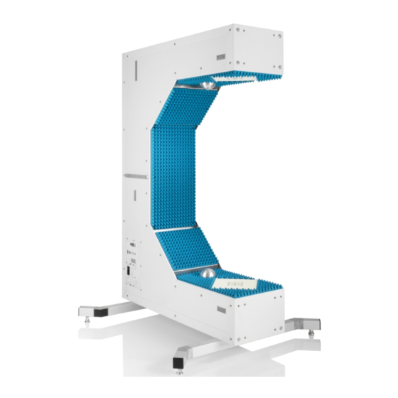
® Instrument tour R&S QAR50 System overview Figure 5-1: System overview Mounting holes Supporting feet Connector board Verification kit mounting rail Calibration sphere Antenna cluster 1 Antenna cluster 2 Absorbers 5.1.1 Connector board Number of connector boards: 1 Function: The connector board provides various interfaces for external applications. -
Page 25: Antenna Cluster
Number of mounting rails: 2 (one on each side of the main body) Function: The mounting rails for the verification kit are located in the center of each side of the R&S QAR50 body. Use these rails to install the verification kit if you have to verify the system. -
Page 26: Supporting Feet
Function: The supporting feet provide a means to support the R&S QAR50. Depending on how you install the R&S QAR50, the supporting feet are either located on the bottom of the main body of the R&S QAR50 or on the side body that contains cluster "2". -
Page 27: Ac Power Supply
Function: AC input for a connection to the AC mains supply. You can connect the R&S QAR50 to networks with different voltage levels (see datasheet for the supported voltage range). The power supply automatically adapts itself to the voltage level of the power source. -
Page 28: Power Button
Figure 5-3: AC power supply 5.2.2 Power button Function: A short press turns the R&S QAR50 on and off when it is connected to an AC power source The power button contains an LED that indicates the state of the R&S QAR50. For more information about the power states, see Chapter 4.6, "Switching on or... -
Page 29: Displayport Connector
5.2.5 DisplayPort connector Connector type: DisplayPort Function: DisplayPort for connection of a touchscreen or monitor that you can use to control the R&S QAR50 and view the measurement results. Figure 5-7: DisplayPort connector 5.2.6 Device ID The unique device identifier is provided as a barcode sticker on the connector board on the side of the R&S QAR50. -
Page 30: Test Setup
The test setup for measurements with the R&S QAR50 basically consists of a R&S QAR50 and a DUT located between the two clusters. The position of the DUT rel- ative to the clusters is determined by a coordinate system, whose origin is the center of cluster 1. - Page 31 The resulting image should show the logo the right way around. Regardless of the position of the R&S QAR50, the center of the logo should be aligned with the center of the clusters. The plate with the logo is thin, so the distance from each cluster is about 0.5 m.
- Page 32 ® Test setup R&S QAR50 Figure 6-3: Example: DUT position for a lying R&S QAR50 ● For the upright position, position the logo like this: Figure 6-4: Example: DUT position for an upright R&S QAR50 Both DUT positions result in a millimeter wave image with the correct orientation.
- Page 33 ® Test setup R&S QAR50 Figure 6-5: Example: Millimeter wave image of the logo User Manual 1179.4992.02 ─ 02...
-
Page 34: User Interface
Measurement preview 10 = Location of measurement result data 11 = System messages Menu bar Contains various functions to configure the R&S QAR50 and the measurement. For more information, see Chapter 9, "Configuration", on page 46 and Chapter 8, "Measurements and result displays",... - Page 35 Measurement preview Shows a preview image of the measurements that you have performed for the DUT. If no preview is available, the preview image is an image of the R&S QAR50. For more information, see Chapter 8, "Measurements and result displays",...
-
Page 36: Measurements And Result Displays
R&S QAR50 Normalization 8 Measurements and result displays The R&S QAR50 provides several measurements and result displays that you can use to evaluate the quality of a DUT. Measurements usually consist of two steps, normalization and the actual measure- ment. -
Page 37: Measurement
DUT. 2. Select "Normalize Reflection" to initiate the normalization. When the normalization measurement is done, the R&S QAR50 saves the correc- tion data. The R&S QAR50 corrects all subsequent measurements accordingly. A valid normalization results in an image with high reflection. The mean reflection should be approximately 0 dB and should not exceed a certain deviation from that value - refer to the datasheet for exact values. -
Page 38: Reflection Measurement
Configure the measurement as required. Normalize the measurement, if necessary. 3. Place the DUT in the center of the R&S QAR50, between the clusters. For a detailed description of the test setup, see Chapter 6, "Test setup", on page 30. -
Page 39: Transmission Measurement
The R&S QAR50 achieves spatially resolved reflection measurements of a DUT by linking the information collected by the distributed transmit and receive antennas in a coherent operation. -
Page 40: Phase Measurement
The opposite cluster measures the phase of the received signal. The resulting phase results are the average of those two measurements. To calculate the phase difference, the R&S QAR50 compares the phase of the normali- zation measurement (empty space) to that of the actual measurement. -
Page 41: Result Displays
For more information about the result display available for the phase measurement, Chapter 8.3, "Result displays", on page 41. 8.3 Result displays The R&S QAR50 provides various result displays that you can use to evaluate the results of the measurements. Millimeter wave image....................41 Result diagram...................... - Page 42 ® Measurements and result displays R&S QAR50 Result displays Available with the optional phase measurement application. Band 1 is the frequency band from 76 GHz to 77 GHz. Band 2 is the frequency band from 76 GHz to 81 GHz.
- Page 43 ® Measurements and result displays R&S QAR50 Result displays A black line within the blue rectangle surrounding certain areas indicates the measure- ment points that deviate no more than 3 dB from the maximum reflection value or the minimum attenuation value. There can be several such areas in the image, depending on the characteristics of the DUT.
- Page 44 The result diagram shows the frequency response of the DUT in terms of the level characteristics of the DUT. The results are displayed as a line trace over a certain fre- quency range. The R&S QAR50 evaluates the frequency range around the typical radar bands.
- Page 45 ® Measurements and result displays R&S QAR50 Result displays The interpretation of the percentage value depends on the measurement. ● Reflection measurement: 100 % reflection = complete energy is reflected by the ● Transmission measurement: 100 % transmission attenuation = complete energy is...
-
Page 46: Configuration
Always make sure that the "Device Properties" are set correctly. Otherwise, measure- ment results can be invalid. 1. Select "Options" > "Settings". 2. Select the position of the R&S QAR50 from the "Shape Setup" menu. ● "U" corresponds to the lying position. - Page 47 Automative radar sensors typically use the frequency bands from either 76 GHz to 77 GHz or from 76 GHz to 81 GHz. By default the R&S QAR50 measures the DUT characteristics in both bands. If you want to test only one of those bands, select the desired band.
- Page 48 ® Configuration R&S QAR50 The value you enter is a deviation from the mean phase that has been measured (mean phase ± dynamic range). Only phase value within that range get different shades of colors in the millimeter wave image. Phase values outside that range are treated as the same phase value and have the same color in the image.
-
Page 49: Data Management
2. Define the default directory in which to save the results in the "Save Path" input field. For each measurement, the R&S QAR50 creates a subfolder that contains the measurement data. This subfolder's name has a variable name that contains the time stamp of the measurement: yyyymmdd-hhmmss. - Page 50 ® Data management R&S QAR50 Image of the measurements (millimeter wave image and frequency response trace). ● <yyyy-mm-dd-hh-mm-ss>_results.mat Contains the raw 2D imaging data and the trace data for the result diagram. ● <yyyy-mm-dd-hh-mm-ss>_volume.mat Contains the raw 3D imaging data.
-
Page 51: System Verification
Installing the frame for the verification objects The verification objects come with a frame that holds the objects. The R&S QAR50 has mounting rails on each side of the main body that can hold the frame. 1. Slide the frame onto the mounting rails of the R&S QAR50. - Page 52 ® System verification R&S QAR50 Figure 11-1: Installing the verification plate frame 2. Secure the frame by tightening the screws on each side of the frame. Verifying the system The verification process consists of four consecutive measurements with the verifica- tion objects (square plates).
- Page 53 ® System verification R&S QAR50 a) Put the metal plate labeled "E" into the frame. Figure 11-2: Mounting verification plates b) Select "Normalize Reflection" to initiate a measurement. c) Wait until the results are displayed. d) Remove the metal plate from the frame.
- Page 54 ® System verification R&S QAR50 After each measurement, check the mean reflection against the limits r and r specified on the stickers attached to the verification plates. The sticker shows the reflection characteristics of the plate and the deviation the result may have.
-
Page 55: Remote Control
62 12.1 Remote control interface and protocol For the R&S QAR50, the remote control interface is the LAN interface. The LAN inter- face consists of a connector, a network interface card and protocols. The network card can be operated with the following interfaces: ●... - Page 56 ® Remote control R&S QAR50 Remote control interface and protocol ● LAN device name defines the protocol and the instance number of a sub-instru- ment; ● INSTR indicates the instrument resource class (optional) Example: ● Instrument has the IP address 192.1.2.3; the valid resource string using VXI-11 protocol is: TCPIP::192.1.2.3::INSTR...
-
Page 57: Remote Control Commands
You have to open several ports in the firewall to be able to communicate via SCPI. By default, these ports are already open on the R&S QAR50. If you want to close these ports, you can run a script that closes these ports. -
Page 58: Measurement:evaluation:window
® Remote control R&S QAR50 Remote control commands During a remote session, the user interface is unavailable. To access the user interface again, you have to return to local mode via the user interface or end the remote ses- sion with >L. -
Page 59: Measurement:normalize:reflection:start
® Remote control R&S QAR50 Remote control commands Return values: <State> 1 | 0 If the result is 1, normalize the measurement with MEASurement:NORMalize:REFLection:STARt. If the result is 0, the measurement is already normlized. You can proceed with the actual measurement. -
Page 60: Measurement:result:directory
® Remote control R&S QAR50 Remote control commands MEASurement:RESult:DIRectory <Directory> Defines the base directory in which measurement are stored. The results themselves are stored in a subfolder of this directory. The subfolder has a fix naming logic. Parameters: <Directory> String containing the path to the directory. -
Page 61: Measurement:start
® Remote control R&S QAR50 Remote control commands MEASurement:STARt Initiates a measurement (reflection, transmission and phase measurement). Example: Chapter 12.3, "Remote control examples", on page 62. Usage: Event SYSTem:EXIT Shuts down the system. Shutting down the system automatically closes the SCPI connection. -
Page 62: Remote Control Examples
R&S QAR50 Remote control examples 12.3 Remote control examples The following examples show a typical sequence of remote commands to perform a measurement with the R&S QAR50. //Initiate SCPI session >R //Query system status SYST:STAT:CODE? //If result = 0, system is ready for operation... -
Page 63: Maintenance, Storage And Disposal
Do not use liquids to clean the measurement electronics. Using liquids can lead to inaccurate measurements. 2. Clean the frame and rear side of the R&S QAR50 with a lint‑free duster. For stub- born dirt, you can also wipe the frame and rear side with a damp rag. - Page 64 ® Maintenance, storage and disposal R&S QAR50 Disposal Disposing electrical and electronic equipment A product that is labeled as follows cannot be disposed of in normal household waste after it has come to the end of its service life. Even disposal via the municipal collection points for waste electrical and electronic equipment is not permitted.
-
Page 65: Contacting Customer Support
® Contacting customer support R&S QAR50 14 Contacting customer support Technical support – where and when you need it For quick, expert help with any Rohde & Schwarz product, contact our customer sup- port center. A team of highly qualified engineers provides support and works with you to find a solution to your query on any aspect of the operation, programming or applica- tions of Rohde &... -
Page 66: Transporting
® Transporting R&S QAR50 15 Transporting Lifting and carrying See: ● "Lifting, carrying and installing the product" on page 5 Packing Use the original packaging material. It consists of antistatic wrap for electrostatic pro- tection and packing material designed for the product. -
Page 67: List Of Commands
® List of commands R&S QAR50 List of commands >L................................57 >R................................57 MEASurement:EVALuation:WINDow.......................58 MEASurement:LOAD............................58 MEASurement:NORMalize:REFLection:REQuired?..................58 MEASurement:NORMalize:REFLection:STARt....................59 MEASurement:NORMalize:TRANsmission:REQuired?...................59 MEASurement:NORMalize:TRANsmission:STARt..................59 MEASurement:RESult:DIRectory........................60 MEASurement:RESult:SAVE:AUTO........................ 60 MEASurement:RESult:SAVE:WHAT........................60 MEASurement:RESult?........................... 59 MEASurement:SAVE?............................. 60 MEASurement:STARt............................61 SYSTem:EXIT..............................61 SYSTem:REBoot..............................61 SYSTem:STATus:CODE?..........................61 User Manual 1179.4992.02 ─ 02...
Need help?
Do you have a question about the QAR50 and is the answer not in the manual?
Questions and answers