Advertisement
Quick Links
Advertisement

Related Manuals for R&S VTE


Summary of Contents for R&S VTE
- Page 1 ® R&S Video Tester Getting Started (E@<Ô2) 2116127002...
- Page 2 "Open Source Acknowledgment" document, which is available for download from the R&S VTE product page at www.rohde-schwarz.com/product/vte.html > "Downloads" > "Firmware". Rohde & Schwarz would like to thank the open source community for their valuable contribution to embed- ded computing.
- Page 3 ® Contents R&S Contents 1 Safety and Regulatory Information........7 1.1 Safety Instructions................7 1.2 Labels on the Product................ 10 1.3 Warning Messages in the Documentation........11 1.4 Korea Certification Class A..............11 2 Documentation Overview............13 2.1 Getting Started Manual...............13 2.2 User Manuals and Help..............13 2.3 Tutorials....................
- Page 4 ® Contents R&S 4.6.3 Memory Stick..................23 4.6.4 External Drive..................23 4.7 Switching On or Off................23 4.8 Checking the Provided Options............25 4.9 Turn-On Tests..................25 5 Instrument Tour..............27 5.1 Front Panel..................27 5.1.1 Standby Key..................28 5.1.2 Cursor Keys..................29 5.1.3 ENTER/ESC Keys................
- Page 5 ® Contents R&S 6 Operating the R&S VTE in a LAN........37 6.1 Connecting the R&S VTE to a Network..........37 6.2 Connecting the R&S VTE to a Computer.......... 38 6.2.1 Windows 7 Operating System...............38 6.2.2 Other Operating Systems..............39 6.3 Zero Configuration Networking............39 6.4 Configuring the Network Card............39...
- Page 6 ® Contents R&S Getting Started 2116.1270.02 ─ 07...
- Page 7 ® Safety and Regulatory Information R&S Safety Instructions Safety and Regulatory Information The product documentation helps you use the product safely and efficiently. Fol- low the instructions provided here and in the Chapter 1.1, "Safety Instructions", on page 7. Intended use The product is intended for the development, production and verification of elec- tronic components and devices in industrial, administrative, and laboratory envi- ronments.
- Page 8 ® Safety and Regulatory Information R&S Safety Instructions If any part of the product is damaged or broken, stop using the product. Never open the casing of the product. Only service personnel authorized by Rohde & Schwarz are allowed to repair the product. Contact Rohde & Schwarz customer service at http://www.customersupport.rohde-schwarz.com.
- Page 9 ® Safety and Regulatory Information R&S Safety Instructions Connecting to power The product is an overvoltage category II product and has to be connected to a fixed installation used to supply energy-consuming equipment such as household appliances and similar loads. Be aware that electrically powered products have risks, such as electric shock, fire, personal injury or even death.
- Page 10 ® Safety and Regulatory Information R&S Labels on the Product Potential hazard Read the product documentation to avoid personal injury or product damage. Electrical hazard Indicates live parts. Risk of electric shock, fire, personal injury or even death. Hot surface Do not touch.
- Page 11 ® Safety and Regulatory Information R&S Korea Certification Class A Warning Messages in the Documentation A warning message points out a risk or danger that you need to be aware of. The signal word indicates the severity of the safety hazard and how likely it will occur if you do not follow the safety precautions.
- Page 12 ® Safety and Regulatory Information R&S Korea Certification Class A Getting Started 2116.1270.02 ─ 07...
- Page 13 Includes the contents of the getting started man- ual. The contents of the user manual is available as help on the R&S VTE. The help offers quick, context-sensitive access to the complete information for the base unit and the software options.
- Page 14 Data Sheets and Brochures The data sheet contains the technical specifications of the R&S VTE. It also lists the options and their order numbers, and optional accessories. The brochure provides an overview of the instrument and deals with the specific characteristics.
- Page 15 R&S Key Features The R&S VTE video test center is a universal platform for testing video and audio interfaces on consumer electronics equipment in R&D where a wide variety of applications need to be addressed and involve different AV interface technolo- gies.
- Page 16 ® Key Features R&S Getting Started 2116.1270.02 ─ 07...
- Page 17 5. Check the equipment for damage. If the delivery is incomplete or equipment is damaged, contact Rohde & Schwarz. For information on warranty conditions for the R&S VTE, refer to the terms of the delivery documents. Getting Started 2116.1270.02 ─ 07...
- Page 18 ® Preparing for Use R&S Choosing the Operating Site Choosing the Operating Site Specific operating conditions ensure accurate measurements and avoid damage to the product and connected devices. For information on environmental condi- tions such as ambient temperature and humidity, see the data sheet. See also "Choosing the operating site"...
- Page 19 ® Preparing for Use R&S Choosing the Operating Site 3. WARNING! A stack of products can fall over and cause injury. Never stack more than three products on top of each other. Instead, mount them in a rack. Stack as follows: ●...
- Page 20 ® Preparing for Use R&S Considerations for Test Setup b) Mount the adapter kit. Follow the assembly instructions provided with the adapter kit. 2. Lift the product to shelf height. 3. Grab the handles and push the product onto the shelf until the rack brackets fit closely to the rack.
- Page 21 31 Connecting External USB Devices Using the USB interfaces, you can directly connect USB devices to the R&S VTE. This number can be increased as necessary by using USB hubs. Due to the large number of available USB devices, there is almost no limit to the possible expansions.
- Page 22 ● Printer for printing measurement results. To install a USB device 1. Connect the USB device to the R&S VTE. You can connect a USB device dur- ing operation because all USB devices are Plug and Play. Windows 7 automatically searches for a suitable device driver.
- Page 23 4.6.3 Memory Stick The R&S VTE has a disk drive. You can exchange data by using a memory stick which you plug into one of the USB interfaces. The memory stick is automatically assigned a free drive letter and you can use Windows Explorer to transfer data.
- Page 24 ● A self-test is performed. After booting is completed, the main screen of the R&S VTE is displayed, and the R&S VTE is ready for operation. The configuration settings that were active before the R&S VTE was last shut- down are automatically restored.
- Page 25 Further information: ● User manual or the help system. For an overview of the all options available for the R&S VTE, refer to the Rohde & Schwarz Homepage. Turn-On Tests During power-on and on an ongoing basis during operation, the R&S VTE auto- matically monitors the main instrument functions.
- Page 26 ® Preparing for Use R&S Turn-On Tests Getting Started 2116.1270.02 ─ 07...
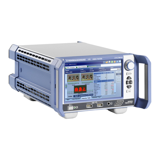
- Page 27 ® Instrument Tour R&S Front Panel Instrument Tour In this manual, the front and rear panel of the base unit are described. In the user manual or the help system, this chapter also includes the following: ● Description of the modules that you can optionally install ●...
- Page 28 For safety information, see "Connecting to power" on page 9. The standby key works only if the AC power switch on the back of the R&S VTE is switched on. The standby key switches the R&S VTE from standby to on and back.
- Page 29 ® Instrument Tour R&S Front Panel 5.1.2 Cursor Keys See (5) in Figure 5-1. Cursor keys <Up Arrow>/<Down Arrow> keys: ● Moves the focus vertically in windows, dialogs, tables and lists. ● If a numeric parameter value is in editing mode, increases or decreases the digit value at the cursor position.
- Page 30 The socket is intended for connecting headphones or an active loud- speaker. The R&S VTE has an internal active loudspeaker. If the jack socket for the L/R analog audio output is connected, the internal loudspeaker is disabled. Getting Started 2116.1270.02 ─ 07...
- Page 31 ® Instrument Tour R&S Rear Panel Rear Panel This chapter provides an overview of the controls and connectors on the rear panel. Each control or connector is briefly described along with a reference to the chapters containing detailed information about its usage. Figure 5-2: Rear panel view = Trigger input = Marker output...
- Page 32 Switch positions: ● [I]: Depending on the setting of the standby key on the front panel, the R&S VTE is either in standby mode or in operation. ● [O]: The entire instrument is disconnected from the AC power supply. Further information: ●...
- Page 33 When using an internal reference, the frequency generated by the internal refer- ence oscillator of the R&S VTE is made available. If an external reference is acti- vated, the signal applied to the reference frequency input is also available here. It is buffered and filtered.
- Page 34 See (8) in Figure 5-2. 1 gigabit LAN interface (1000 Base-T). Used to connect the R&S VTE to a local network for remote control, remote operation, printouts and data transfer. The assignment of the RJ.45 CAT5 connector supports twisted-pair category 7 UTP/STP cables in a star configuration (UTP stands for "unshielded twisted pair",...
- Page 35 Figure 5-2. USB 2.0 (universal serial bus) interface of the type B (receptacle). Used to con- nect the R&S VTE to a computer. Electromagnetic interference (EMI) can affect the measurement results. To avoid any impact, follow the instructions in "Cable selection and electro- magnetic interference (EMI)"...
- Page 36 ® Instrument Tour R&S Rear Panel Description TMDS data0+ TMDS data0 shield TMDS data0– TMDS clock+ TMDS clock shield TMDS clock– Reserved (not connected) DDC/CEC ground +5 V power (+5 V / 500 mA) Hot plug detect Getting Started 2116.1270.02 ─ 07...
- Page 37 Connecting the R&S VTE to a Network Operating the R&S VTE in a LAN The R&S VTE is equipped with a network interface and can be connected to an Ethernet LAN (local area network). The network card operates with 1000 Mbit Ethernet IEEE 802.3ab.
- Page 38 To connect the R&S VTE to a network 1. Fulfill all prerequisites mentioned above. 2. Make sure that the R&S VTE is switched off. This is the only way to ensure that the network connection is reliably detected and any disruptions during the operation of the R&S VTE are avoided.
- Page 39 Configuring the Network Card Under Windows 7, network card drivers do not need to be installed separately. If the R&S VTE is connected to the LAN, Windows 7 automatically detects the net- work connection and activates the required drivers. Getting Started 2116.1270.02 ─ 07...
- Page 40 IP address. Identification in the network is based on the use of a unique computer name. Every R&S VTE is assigned an individual computer name at the factory. It is dis- played as part of the window title of the application.
- Page 41 By default, the Windows Firewall is activated to protect the R&S VTE from an attack of hostile users and programs. The Windows Firewall suppresses all net- work communication which is not initialized by the R&S VTE itself or which is not defined as an exception.
- Page 42 ® Operating the R&S VTE in a LAN R&S Firewall Settings Getting Started 2116.1270.02 ─ 07...
- Page 43 The R&S VTE is equipped with the Windows 7 Embedded operating system in the 32-bit version. When the R&S VTE is delivered, the operating system is con- figured for optimum operation. Changes to the system settings are required only if you install peripherals such as a keyboard and printer or if you configure the net- work and the settings do not conform to the default settings.
- Page 44 R&S Backup and Restore Application If the R&S VTE is connected to a network and if the login data under Windows 7 and on the network is identical, you log on to operating system and the network at the same time.
- Page 45 If the instrument does not have a monitor, connect also an external monitor. To display the main dialog for backup and restore 1. Restart the R&S VTE. The boot screen is displayed. By default, "System" is selected. If you do not perform the next step within 4 seconds, the dialog vanishes and the booting process continues.
- Page 46 ® Installed Software R&S Backup and Restore Application Figure 7-1: Main dialog (example) (1) = Header showing instrument type (2) = Header showing instrument name (3) = Free memory space on backup partition (4) = List of backups already created (5) = Description of currently selected backup To continue, see one of the following chapters: ●...
- Page 47 Note: If you activate "Keep open when finished", the progress information dia- log remains open until you close it. 4. In the main dialog, select "Exit and Reboot". The backup and restore application is closed, and the R&S VTE is restarted. 7.3.2 Restoring a Selected Backup Version Using this function, you can restore the selected instrument installation and its configuration.
- Page 48 ("Cancel"). After the process has been finished, the application is closed automatically, and the R&S VTE is restarted. Note: If you activate "Keep open when finished", the progress information dia- log remains open until you close it.
- Page 49 ® Contacting Customer Support R&S Contacting Customer Support Technical support – where and when you need it For quick, expert help with any Rohde & Schwarz product, contact our customer support center. A team of highly qualified engineers provides support and works with you to find a solution to your query on any aspect of the operation, program- ming or applications of Rohde &...
- Page 50 ® Contacting Customer Support R&S Getting Started 2116.1270.02 ─ 07...
- Page 51 ® Index R&S Index DVI connector ..........33 AC power supply Connecting to ........21 Electromagnetic interference AC power supply connector ....31 Preventing ...........20 AC power switch ........31 EMC classes ........... 18 Administrator ID ........43 EMC precautions ........20 Application cards ........14 ENTER key ..........29 Application notes ........
- Page 52 ® Index R&S Right arrow key ........29 Rotary knob ..........30 Labels ............10 LAN connector .........34 Left arrow key .......... 29 Safety information ........7 Lifting ............17 Safety instructions ........14 Local area network (LAN) ....34, 37 Shipping damage inspection ....
Need help?
Do you have a question about the VTE and is the answer not in the manual?
Questions and answers