
Related Manuals for Shire Larkspur


Summary of Contents for Shire Larkspur
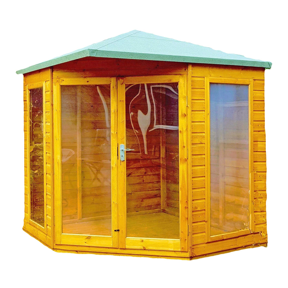
- Page 1 Mass: 271.2 kg © 8x8 Larkspur These instructions are for your safety. Please read through them thoroughly before use. PLEASE KEEP THIS LEAFLET FOR FUTURE REFERENCE...
-
Page 2: Table Of Contents
Fascia & Nail List Detailed Technical Drawing 08-09 Hardware chart Before you start Assembly instructions 12-24 Like us, Follow us, Recommend us & Tag us Shire Garden Buildings @shiregardenbuildings Shire Garden Buildings customerservice@shiregb.co.uk Brigstock Road Wisbech Cambridgeshire PE13 3JJ Tel 01945 465 295... -
Page 3: Safety
Safety Check that you have noted all the following instructions: We advise the use of non slip protective gloves throughout the assembly process. We advise the use of steel capped protective footwear throughout the assembly process. We advise that you use a helper to hold the glass in position whilst you nail the beading in place. -
Page 4: Preparation Of Base
Base and Warranty Preparation of base... We recommend that the base onto which your building will stand should be at least 75mm larger in each direction than the total floor size of the building. Actual floor area of the building: 2390mm x 2390mm ... -
Page 5: Care, Maintenance & Recycling
Care, Maintenance and Recycling The 5 golden rules of care: Ensure your base is level and firm. Ensure the building is not sitting directly on the ground using damp proof membrane or the optional timber base. Ensure every piece of timber and surface, especially that is hidden upon assembly is treated with a top quality wood preservative at least twice (before assembly). -
Page 6: Parts List
Stacked Parts List Description (part No ) - Qty... -
Page 7: Fascia & Nail List
Fascia Bag Parts List Description (part No ) - Qty... -
Page 10: Hardware Chart
Nail bag contents Description (part No ) - Qty Hardware Chart Scale 1:1 16mm Panel Pins (A0024) x 72 13mm 13mm Felt Nail (A0023) x 432 40mm Round Head Nail (A0025) x 24 25mm Posi-Drive Screw (A0032) x 08 40mm Posi-Drive Screw (A0033) x 32 60mm Posi-Drive Screw (A0035) x 49... -
Page 11: Before You Start
Before you start... Things to check before you start: Ensure your base is ready – See page 3 Check all parts as listed in the parts lists Read the instructions fully before starting work Follow all the health and safety guidelines. When you see the drill icon Only ever drill through the first piece of framework which will be a... -
Page 12: Assembly Instructions
Assembly instructions: These instructions are for your safety. Please read through them thoroughly before use. Treat all the parts before assembly – see page 5! The “Panel layout” is showing you how to position the panels. GB-IE The Plain Panels FIT INSIDE THE WINDOW PANELS! A4228 Double Door Gable If using a drill... - Page 13 Drill the LH Plain Panel (A4227) and the RH Plain Panel (A4228) as below. GB-IE Put the Floor Panel (A3140) onto your base. Place the LH Panel into the corner, so that the cladding overlaps the floor. Push the RH Panel up to it and fix with 3x 60mm Screws (A0035) using the pilot holes drilled in the panel.
- Page 14 Drill the LH Window Panel (A4471) and RH Window Panel (A4472) as below. GB-IE Place the panels so that the cladding overlaps the floor. Secure to your building using 3x 60mm Screws (A0035) within the pilot holes drilled in the LH+RH Plain Panel. NOTE Some holes drilled for...
- Page 15 Open the doors. GB-IE Drill the Double Door Gable (Step 01) as below. Place onto the floor so that the cladding overlaps. Secure with 3x 60mm Screws (A0035) in each side, within the pilot holes drilled in the window panels. DO NOT SCREW THROUGH DOORS. NOTE Some holes drilled for...
- Page 16 1 Strip of Felt 8m (A4081) has been supplied. Roll our the felt on a clean, flat surface. Place GB-IE one Roof Panel (A4229) onto the felt as below. Allow 56mm overhang along the bottom. Cut along the angled sides as below. Fold the felt over the flat edge, pull tight and secure with 13mm Felt Nails (A0023) approximately 100mm apart.
- Page 17 Using the same roll of 8m Felt (A4081), place the Roof Panel (Step 05) onto the felt, making sure it sits GB-IE 670mm below the felt as below. Cut along the angled edge as before. Use Felt Strip 5.3m (A4506) if you run out.
- Page 18 Place the first two Roof Panels (Step 06) onto your building as below. Make sure the panels GB-IE fit into the slots within the wall panels. Fix the panels together with 3x 60mm Screws (A0035) using the pilot holes drilled in one panel.
- Page 19 GB-IE Place the third and fourth Roof Panel (Step 06) into your building as below. Make sure it is placed within the slots in the wall panels. Fix together with 3x 60mm Screws (A0035 Roof Panel (A4513)x02 (Step 06) 60mm Screws (A0035)x09 Window panel omitted for assembly illustration clarity only...
- Page 20 On the inside, screw at an angle, through the wall panels and into the roof panels as below. Use 60mm Screws (A0035) as below. 60mm Screws (A0035)x10 SCREW AT AN ANGLE SCREW AT AN ANGLE IN EACH CORNER...
- Page 21 Use a helper to fold the Profiled Coverstrips 19x34x1880 (A07666) in place as below. GB-IE Secure each side of the coverstrips with 4x 40mm Screws (A0033) making sure the strips are secured to each of the roof triangles. You may need to cut the strips to fit! Where the coverstrip meets the door panel, you need to measure and cut the strips in two pieces so that they can be placed either side of the door as below.
- Page 22 Roll out what is left of the Felt Strip 5.3m (A4506) onto a clean, flat surface. GB-IE Mark out and cut four strips as below. Make sure each strip measures 245mm wide and 2100mm long. Use a straight edge (e.g. wood) to help cut the strips. 2100mm Felt Strip 5.3m 245mm...
- Page 23 Make sure everything is square and true. GB-IE Fix the walls to the floor with 60mm Screws (A0035) using the pilot holes drilled in the previous steps. 60mm Screws (A0035)x10 Fit the two Profile Coverstrips 19x34x1900 (A1394) to the front corners of your building as below.
- Page 24 GLASS HANDLE WITH CARE, DANGER OF CUTTING GB-IE Using a helper, hold the Glass 1534x547 (A1317) in place. Nail the Beading 550mm (A0075) at the top and bottom with 3 pins in each. Nail the Beading 1538mm (A1408) with 6 pins to the sides. Use 16mm Panel Pins (A0024). Glass 1534x547 (A1317)x04 Beading 550mm...
Need help?
Do you have a question about the Larkspur and is the answer not in the manual?
Questions and answers