
Subscribe to Our Youtube Channel
Related Manuals for Shire 6x4 Bar


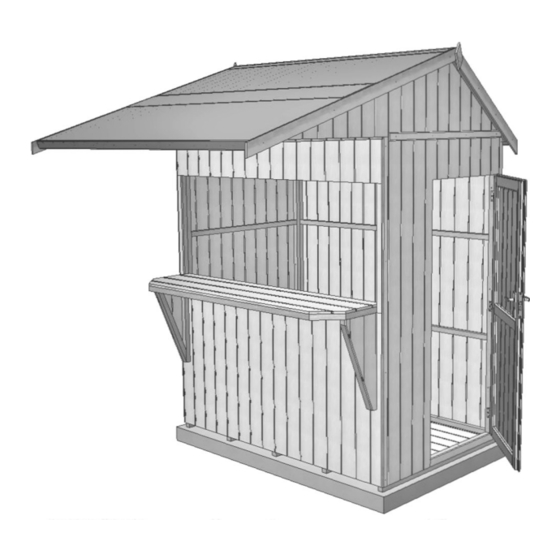
Summary of Contents for Shire 6x4 Bar
- Page 1 © 6x4 Bar 7These instructions are for your safety. Please read through them thoroughly before use. PLEASE KEEP THIS LEAFLET FOR FUTURE REFERENCE...
-
Page 2: Table Of Contents
Let’s get started... Important information... Safety Preparation of base Warranty Care, maintenance & Recycling In more detail... Parts List Fascia & Nail List Hardware chart Before you start Detailed Technical Drawing 10-11 Assembly instructions 12-24 For a copy of the instructions or a copy in another language please send an email or write to the address below. -
Page 3: Safety
Safety Check that you have noted all the following instructions: We advise the use of non slip protective gloves throughout the assembly process. We advise the use of steel capped protective footwear throughout the assembly process. We advise that you use a helper to hold the glass in position whilst you nail the beading in place. -
Page 4: Preparation Of Base
Base and Warranty Preparation of base... We recommend that the base onto which your building will stand should be at least 75mm larger in each direction than the total floor size of the building. Actual floor area of the building: 1790mm x 1190mm ... -
Page 5: Care, Maintenance & Recycling
Care, Maintenance and Recycling The 5 golden rules of care: Ensure your base is level and firm. Ensure the building is not sitting directly on the ground using damp proof membrane or the optional timber base. Ensure every piece of timber and surface, especially that is hidden upon assembly is treated with a top quality wood preservative at least twice (before assembly). -
Page 6: Parts List
Stacked Parts List Description Scale 1:70 unless stated (part No ) - Qty... -
Page 7: Fascia & Nail List
Stacked Parts List Description Scale 1:70 unless stated (part No ) - Qty Fascia Bag Parts List Description no scale (part No ) - Qty... -
Page 8: Hardware Chart
Nail bag contents Description -- (part No ) - qty: Hardware Chart Scale 1:1 13mmFelt Nail (A0023) x124 40mmRound head nail (A0025) x60 25mm Posi-drive screw (A0032) x24 Black 25mm Posi-drive screw (A0031 ) x08 40mm Posi-drive screw (A0033) x04 60mm Posi-drive screw (A0035) x68... -
Page 9: Before You Start
Before you start... Things to check before you start: Ensure your base is ready – See page 4 Check all parts as listed in the parts lists Read the instructions fully before starting work Follow all the health and safety guidelines. When you see the drill icon Only ever drill through the first piece of framework which will be a... -
Page 12: Assembly Instructions
Assembly instructions: These instructions are for your safety. Please read through them thoroughly before use. Treat all the parts before assembly – see page 5! GB-IE See page 4 for base recommendation. We have used concrete for our example. Make sure the floor is situated as shown. The open long side of the floor is the front. Floor panel (A0085)x01 Front... - Page 13 Fix the two D-handles A0089 to the outside of the shutter so the 25mm black screws go into the GB-IE framework. Fix a A0014 Bolt at each corner framework with 4x25mm screws each. Sutter (A2439) x01 D-handle (A0089) x02 Bolt (A0014) x04 25mm Black Screw (A0031)x08...
- Page 14 Remove the transport blocks from the bottom of the panels gently with a hammer Drill the panels as shown. Some of the holes will be used in later steps. GB-IE The Back panel A2421 fits the full length of the floor and the cladding overhangs the floor. Push the door panel A2422 up to it and ensure both panels are tight to the floor and the framework is flush before fixing.
- Page 15 Again drill holes in both sides and the bottom of the plain side although only 3 holes are for this step. GB-IE Position the A2424 plain side flush and true as before. Fix to the back with 3x 60mm screws. 5 mm Building Photographs...
- Page 16 The A2423 front panel needs no holes in the end framework GB-IE Again the bottom edge must be drilled inline with the floor framework Like the back the front fits in front of the sides and runs the length of the floor. Fix using the holes drilled in steps 4&5 5 mm Front panel...
- Page 17 Drill the A2425 RH gable panel making sure both holes are within 1m of the steep end. GB-IE Align the framework and fix to the panel below 5 mm Rh Gable Panel (A2425)x01 60mmScrew (A0035)x02 GB-IE Repeat at the other end with the A2426 LH gable. 5 mm Lh Gable (A2426)x 01...
- Page 18 Drill 6 holes in the A2430 soffit panel GB-IE Align the framework on top of and with the inside of the front panel frame and with the gables framework. Fix to the gables first and then to the front panel with the holes drilled earlier. 5 mm Soffit Panel (A2430) x01...
- Page 19 Position the A2431 Large roof as for the back one GB-IE Drill and fix the up the gable slopes as before NOTE using nail lines as a guide drill through the support bars. Mark and drill 180mm from the low edge and screw to the soffit’ 5 mm Large Roof (A2431)x01...
- Page 20 3 Strips of felt have been supplied. Fit the front lower strip first folding the felt over the roof edging, GB-IE with an even overhang front and back then secure with a couple of nails at the top to hold the felt in position and at the bottom nail at approximately 100mm centres.
- Page 21 The second piece overlaps the lower one and goes over the ridge.Nail at approximately 100mm centres GB-IE and a couple at the top to hold. 2.0m Felt strip (A2433)x01 13mm Felt nails (A0023) x44 The third piece covers the small roof and folds around the sides as before. GB-IE The top edge goes over the ridge.Nail at approximately 100mm spaces as before 2.0m Felt strip...
- Page 22 Drill a hole through the short framework on the A2427 &A2428 braces. Place some masking tape below the opening in the front at each outer edge and mark and drill two holes GB-IE either side as dimensioned below. Align the braces flush with the opening and fix from the inside. RH brace (A2427) x01 LH brace...
- Page 23 Place the A2429 bar shelf on top of the braces and into the aperture of the front panel so the framework GB-IE is flush. Screw through the front panel using the holes drilled earlier and then through the braces. 5 mm Bar Shelf (A2429) x01 60mm Screws...
- Page 24 Fit cover strips at each corner and across the joins with 4 nails each. GB-IE A2436 2012mm for corners A2437 1122mm for gable joins 46mm Cover strip (A2436) x04 46mm Cover strip (A2437) x02 40mm Nail (A0025) x24 It is best to lay the fascia's on the floor so you can turn them over to ensure you have them the right way GB-IE around, Drill with a 1 mm drill to stop splitting.
Need help?
Do you have a question about the 6x4 Bar and is the answer not in the manual?
Questions and answers