
Related Manuals for Shire Highclere


Summary of Contents for Shire Highclere
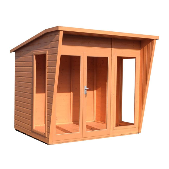
- Page 1 Mass: 254.4 kg © 8x6 Highclere These instructions are for your safety. Please read through them thoroughly before use. PLEASE KEEP THIS LEAFLET FOR FUTURE REFERENCE...
-
Page 2: Table Of Contents
Let’s get started... Important information... Safety Preparation of base Warranty Care, maintenance & Recycling In more detail... Parts List Fascia & Nail List Hardware chart Before you start Detailed Technical Drawing 10-11 Assembly instructions 12-24 For a copy of the instructions or a copy in another language please send an email or write to the address below. -
Page 3: Safety
Safety Check that you have noted all the following instructions: We advise the use of non slip protective gloves throughout the assembly process. We advise the use of steel capped protective footwear throughout the assembly process. We advise that you use a helper to hold the glass in position whilst you nail the beading in place. -
Page 4: Preparation Of Base
Base and Warranty Preparation of base... We recommend that the base onto which your building will stand should be at least 75mm larger in each direction than the total floor size of the building. Actual floor area of the building: 2300mm x 1790mm ... -
Page 5: Care, Maintenance & Recycling
Care, Maintenance and Recycling The 5 golden rules of care: Ensure your base is level and firm. Ensure the building is not sitting directly on the ground using damp proof membrane or the optional timber base. Ensure every piece of timber and surface, especially that is hidden upon assembly, is treated with a top quality wood preservative at least twice (before assembly). -
Page 6: Parts List
Stacked Parts List Description (part No ) - Qty... -
Page 7: Fascia & Nail List
Fascia and Nail Bag Parts List Description (part No ) - Qty... -
Page 8: Hardware Chart
Nail bag contents Description (part No ) - Qty Hardware Chart Scale 1:1 16mm Panel Pins (A0024) x90 13mm 13mm Felt Nail (A0023) x226 40mm Round head nail (A0025) x28 25mm Posi-drive screw (A0032) x08 60mm Posi-drive screw (A0035) x58... -
Page 9: Before You Start
Before you start... Things to check before you start: Ensure your base is ready – See page 4. Check all parts as listed in the parts lists. Read the instructions fully before starting work. Follow all the health and safety guidelines. When you see the drill icon Only ever drill through the first piece of framework which will be a... -
Page 12: Assembly Instructions
Assembly instructions: These instructions are for your safety. Please read through them thoroughly before use. Treat all the parts before assembly – see page 5! GB-IE The 8’ Plain Panel, Door and Window Panel FIT INSIDE THE RH & LH Window Panels ! The “Panel Layout”... - Page 13 GB-IE Fix the Door Handle (A2179) to the Double Door Panel (A5644) as shown below. Make sure the Handle is fixed to the primary door (the door that is opened first). Fix with 25mm Screws (A0032). If using a drill or electric screwdriver carefully but firmly push the opposite end...
- Page 14 Drill the LH Window Pent (A5653) and the Plain Panel (A5641) as below. Make sure the GB-IE holes in the LH Window Pent are inline with the floor bearers. Place the LH Window Pent onto the floor into the corner and push the Plain Panel up to it and fix with 60mm Screws (A0035). NOTE Some holes drilled for...
- Page 15 Drill the RH Window Pent (A5654) as below, making sure the holes are inline with the floor GB-IE bearers. Fix with 60mm Screws (A0035) using the pilot holes drilled in the previous step. NOTE Some holes drilled for later use RH Window Pent (A5654)x01 60mm Screws...
- Page 16 GB-IE Drill the Double Door Panel (A5644) as below. Make sure you don’t drill through the doors. Place the panel onto the edge of the floor and fix with 3x 60mm Screws (A0035). NOTE Double Door Panel (A5644)x01 Some holes drilled for later use 60mm Screws...
- Page 17 GB-IE Drill the Window Panel (A5645) as below. Make sure the holes are drilled at an angle as the drill will not fit in between the bars. Fix the panel with 6x 60mm Screws (A0035) using the holes drilled previously. NOTE Window Panel (A5645)x01...
- Page 18 Drill the LH Roof Panel (A5655) as below. Drill through the top as below, mark to make sure the holes are GB-IE drilled so that the panel can be secured into the walls. Flip over and drill two holes along the edge that sits against the front Door and Window Panels.
- Page 19 Drill the RH Roof Panel (A5655) as below. Turn over and drill two holes in the side that sits along the GB-IE front Door and Window Panel. Drill three holes along the side that joins the two panels together. Fix with 60mm Screws (A0035) as below.
- Page 20 GB-IE Drill the Soffit (A5639) as below. The second view shows which end the drills should be placed. Make sure the holes are drilled so that the screws go into the walls and that the Soffit is secured to the building. Fix with 60mm Screws (A0035).
- Page 21 GB-IE Make sure your building is square and true. Fix the walls to the floor using the pilot holes drilled in the previous steps. 60mm Screws (A0035)x10 Fix the Coverstrips 12x46x1837 (A3986) to the back of your building as below. GB-IE Fix the Coverstrip 12x46x2086 (A5649) to the front of your building as below.
- Page 22 3 Strips of 2.7M Felt (A2555) have been supplied. GB-IE Fit the first and second piece of felt as shown below, making sure there is an even overhang front and back. Pull the Felt tight and secure with 13mm Felt Nails (A0023) approximately 100mm apart.
- Page 23 Fit the last piece of Felt (A2555) on the top of your building. GB-IE Fix the same as the others with 13mm Felt Nails (A0023). Tidying the corner 2.7M Felt Strip (A2555)x01 13mm 13mm Felt Nails (A0023)x56 Fix the Fascia 19x145x2480 (A4445) to the front of the building. GB-IE Then fit the Fascia 19x145x470 (A5650) and Fascia 19x145x1941 (A4446) to the sides using 40mm Nails (A0025).
- Page 24 GB-IE Fit the Acrylic 1534x547 (A1317) as shown below. Whilst someone holds the acrylic, fit the Beading 1538 (A0073) with 6 pins, and the Beading 550 (A0075) with 3 pins in front. WEAR THE CORRECT SAFETY EQUIPMENT Acrylic 1534x547 (A1317)x05 Beading 1538 (A0073)x10 Beading 550...
Need help?
Do you have a question about the Highclere and is the answer not in the manual?
Questions and answers