
Related Manuals for Shire 4X6 Overlap 2018


Summary of Contents for Shire 4X6 Overlap 2018
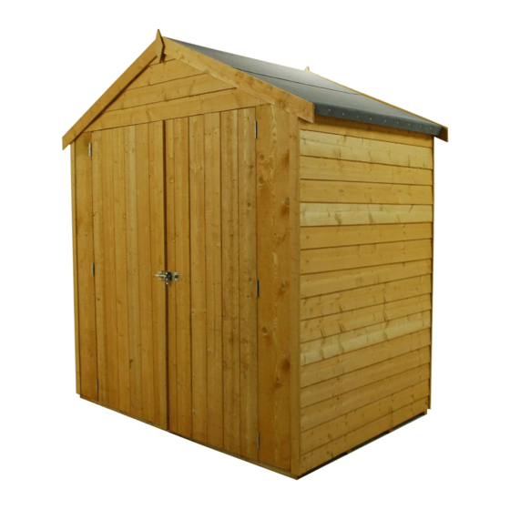
- Page 1 © Shire 4X6 Overlap 2018 These instructions are for your safety. Please read through them thoroughly before use . PLEASE KEEP THIS LEAFLET FOR FUTURE REFERENCE...
-
Page 2: Table Of Contents
Let’s get started... Important information... Safety Base and positioning Warranty Care maintenance & Recycling In more detail... Stacked and Fascia Parts List 06-07 Detailed Technical Drawings 08-09 Hardware 10-11 Before you start Assembly instructions 12-24 For a copy of the instructions or a copy in another language please send an email or write to the address below. -
Page 3: Safety
Safety Check that you have noted all the following instructions We advise the use of non slip protective gloves throughout the assembly process. We advise the use of steel capped protective footwear throughout the assembly process We advise that you use a helper to hold the glass in position whilst you nail the beading in place We advise the use of protective headwear and safety goggles throughout the assembly process... -
Page 4: Base And Positioning
Base and Warranty Preparation of base... We recommend that the base onto which your building will stand should be at least 75mm larger in each direction than the total floor size of the building. Actual floor area of the building: 1828mm x 1197mm Total height clearance: 2166mm Roof size: 1994mm x 1302mm l The chosen position in your garden for your building should be excavated to a depth... -
Page 5: Care Maintenance & Recycling
Care, Maintenance and Recycling The 5 golden rules of care Ensure your base is level and firm Ensure the building is not sitting directly on the ground using damp proof membrane or the optional timber base. Ensure every piece of timber and surface, especially that is hidden upon assembly is treated with a top quality wood preservative at least twice (see note on pressure treated buildings in warranty section). -
Page 6: Stacked And Fascia Parts List
Stacked parts list Description (part No ) qty... - Page 7 Stacked, Fascia & Nail bag contents...
-
Page 10: Hardware
Nail bag contents Hardware Chart Scale 1:1 8mmFelt Nail (A0266) x100 40mmRound head nail (A0025) x96 25mm Posi-drive screw (A0032) x50 60mmPosi-drive screw (A0035) x44... -
Page 11: Before You Start
Before you start Things to check before you start Ensure your base is ready– See page 3 Check all parts as listed in the parts lists Read the instructions fully before starting work Follow all the health and safety guidelines When you see the drill icon Only ever drill through the first piece of framework which will be a... -
Page 12: Assembly Instructions
Assembly These instructions are for your safety. Please read through them thoroughly before use . Treat the parts before assembly –see page 5 GB-IE The “Panel layout” is showing you how you layout the panels. The door end panels and the opposite end panels FIT INSIDE THE SIDE PANELS! A1427 Panel Floor panel... - Page 13 Drill one Plain Panel 1197 (A1427), making sure the holes are inline with the floor bearers. Drill one Plain Panel 880 (A1428) as below. GB-IE Place the plain panel 1197 onto the floor, so that the cladding overlaps. Push the plain panel 880 up to the 1197 panel and secure with 3x 60mm Screws (A0035) using the pilot holes drilled.
- Page 14 Drill the other Plain Panel 880 (A1428) as below. Place onto the floor, next to the other 880 panel and secure with 3x 60mm Screws (A0035) using the pilot holes drilled in the other panel. Drill the other Plain Panel 1197 (A1427), making sure the holes are inline with the floor bearers as below.
- Page 15 Drill the Plain Wing 200 (A1429) panels as below. GB-IE Place onto the floor in between the plain panels 1197 as below. Secure with 3x 60mm Screws (A0035) in each side. Note: May have to screw at an angle. 5 mm Plain Wing 200 (A1429)x02 60mm Screw...
- Page 16 Place the Gables (A0840) onto the building so that the framework is flush. Secure with 4x 60mm Screws (A0035) through the back gable as below. GB-IE For the front gable, secure with 2 screws on the outer edges, then screw through the top of the wing panels as below.
- Page 17 Fix one Roof Edge 34x34 (A0842) along the 1209mm edge of the Roof 1080x1209 (A0121) using 5x 40mm Nails (A0025). Repeat so you have 2 osb roof panels. GB-IE Place onto the building as below. Make sure the top of the roof panel is flush with the top of the roof bearers.
- Page 18 The larger outer part of the Hurling Hinge 4” (A4241) fixes to the Rustic Door (A4257) framework that is flush with the cladding on the end of the door. GB-IE The round pivot part protrudes just over the cladding. The countersink must be facing outwards and fix with 3 screws through the outer hinge. Repeat. Rustic Door (A4257)x02 Hurling Hinge 4”...
- Page 19 Make sure everything is square and true. GB-IE Fix the walls to the floor with 1x 60mm screw (A0035) using the holes drilled previously. 60mm Screw (A0035)x08 Fix the Door Stop 12x28x1360 (A0050) to the gable as below. Make sure the edge is flush with outside gable framework NOT the cladding.
- Page 20 Fit a Barrel Bolt (A0014) to the top and bottom of the secondary door with a Bolt Spacer GB-IE (A0542) between the bolt and the door using 4x 25mm Screws (A0032). Make sure the screws go through the door bolt and the shim directly into the door. Then drill an 8mm hole for the bolt shaft.
- Page 21 Fix the Pad Bolt (A0053) to the primary door as below. GB-IE Secure with 4x 25mm Screws (A0032). Fix the catch to the secondary door using 2x 25mm Screws (A0032). Pad Bolt (A0053)x01 25mm screws (A0032)x06 Take one Coverstrip 12x48x1680 (A1432) and place against the primary door. Mark above and below the pad bolt as below.
- Page 22 GB-IE 3 Strips of Felt 1.3m (A0126) have been supplied . Fit the 2 lower strips first folding the felt over the roof edging, with an even overhang front and back then secure with a couple of nails at the top to hold the felt in position and at the bottom nail at approximately 100mm centres using 8mm Felt Nails (A0266).
- Page 23 Fix the Coverstrips 12x48x1680 (A1432) using 4x 40mm Nails (A0025) in each coverstrip GB-IE as below. Coverstrip 12x48x1680 (A1432)x05 40mm Nails (A0025)x20 Fix the Fascia 12x70x1145 (A0124) to the front and back of the building as below using 3x GB-IE 40mm Nails (A0025) in each.
Need help?
Do you have a question about the 4X6 Overlap 2018 and is the answer not in the manual?
Questions and answers