Table of Contents
Advertisement
Quick Links
Advertisement
Table of Contents

Related Manuals for AVer FC2020-P1


Summary of Contents for AVer FC2020-P1
- Page 1 AVer FC2020-P1 User Manual...
-
Page 2: Table Of Contents
Table of Contents PREFACE ..........................1 PRODUCT SPECIFICATIONS ..................... 1 PACKAGE CONTENTS ....................... 5 PRODUCT INSTALLATION ....................6 ......................6 ONITOR ETTING I/O P .............. 7 ARDWARE NSTALLATION AND SSIGNMENT E) ..................10 OWER THERNET IP A ........................ 11 SSIGNMENT “NXU L ”........ - Page 3 > U ..................26 YSTEM ANAGEMENT > N > S ................28 YSTEM ETWORK ETTING ETTING > N > S ................29 YSTEM ETWORK ETTING EVER > N > DDNS ................30 YSTEM ETWORK ETTING > N > O 1 ................32 YSTEM ETWORK ETTING...
- Page 4 > S ......................62 VENT CHEDULE > DI/DO ....................... 63 VENT ....................... 64 TATUS NFORMATION NETWORK CONFIGURATION ..................65 FACTORY DEFAULT ......................67 TROUBLESHOOTING ....................... 68 APPENDIX ......................... 69 FCC NOTICE (CLASS A)....................70 COPYRIGHT ........................70 LIMITED WARRANTY ....................... 71 GOVERNING LAW AND YOUR RIGHTS ................
-
Page 5: Preface
ENGLISH Preface The FC2020-P1 is a compact cube camera for indoor use with two-way audio communication. It has the added security of a Micro SD based local backup capacity ensuring that images of events also save locally when the alarm is triggered or the network is down. This compact camera offers HD720p resolution and advanced features including intelligent motion detection and privacy masks. - Page 6 Specifications Hardware Multimedia SoC 256MB Flash 1 / 2.7” Mega-Pixel CMOS sensor Image sensor Lens Type 2.8mm@F2.0, Megapixel fixed lens View Angle 103°(H), 61°(V) Shutter time 1/5~1/33,000 sec Min. illumination Color : 1.0 Lux (IR LED ON) B / W: 0 Lux (IR LED ON) 1 Sensor in /1 Relay out MIC in Audio Out...
- Page 7 ENGLISH System Video Resolution 1920x1080@30fps, 1280x720@30fps, 640x480@30fps, 320x240@30fps, 176x144@30fps Brightness, Contrast, Hue, Saturation, Sharpness, Video Adjust AGC, Shutter Time, Sense-up, D-WDR, Lens Distortion Correction, Flip, Mirror, Day&Night adjustable, Red Gain and Blue Gain, Denois Triple Streaming Image snapshot Full screen monitoring Privacy Mask Yes, 5 different areas Compression format...
- Page 8 Web browsing requirement Windows 7, XP Microsoft® IE 8.0 or above [Note] Please enable “Compatibility View” while using IE 10 or above. ® Intel Dual Core 2.53GHz, RAM: 1024MB, Graphics Hardware Suggested Card: 128MB Mobil support iOS 5 or above, Android 1.6 or above. *SPECIFICATIONS ARE SUBJECT TO CHANGE WITHOUT NOTICE.
-
Page 9: Package Contents
ENGLISH Package contents Item Descriptions 1. FC2020-P1 2. Bracket 3. Screw pack 4. Power Adaptor(DC 12V/0.5A) (Optional) 5. CD (User’s Manual and Quick Guide, NVR software included) -
Page 10: Product Installation
Product Installation Monitor Setting 1. Right-click on the desktop. Select “ Properties” 2. Change “Color quality” to “Highest (32-bit)”. -
Page 11: Hardware Installation And I/O Pin Assignment
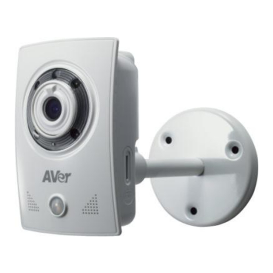
ENGLISH Hardware Installation and I/O Pin Assignment 1. Install with bracket Please refer to the picture for camera installation. Use the screws to lock the bracket to the wall or ceiling, and then connect the camera to the bracket. There’s a knob on the back of the bracket. Loosen the knob and you can adjust the angle of camera. - Page 12 2. Connector Instruction The camera connectors are as below. Connect the power and the Ethernet cable with the camera, and set it according to your network environment. AUDIO ETHERNET DI/DO DC 12V MICROPHONE POWER DEFAULT BUTTON MICRO SD CARD SLOT PIR SENSOR 3.
- Page 13 ENGLISH 4. I/O Configuration I/O Connection a. Please connect the G & DO pin to the external relay (buzzer) device When no event happens, DO output is 5V (DO and GND are disconnected). When the camera detects an event happening and triggers an external alarm, DO output is 0V (DO and GND are connected).
-
Page 14: Power Over Ethernet (Poe)
Power Over Ethernet (PoE) Set up the IP camera through Power over Ethernet (PoE). PoE is a technology that integrates power into a standard LAN infrastructure. It enables power to be provided to the network device, such as an IP camera, using the same cable that is used for network connection. It eliminates the need for power outlets at the camera locations. -
Page 15: Ip Assignment
Finding IP Camera by using the “NXU Lite recording software” Finding IP Camera by using the “AVer IPCam Utility” Finding IP Camera by using “NXU Lite recording software” 1. The NXU Lite software is in the attached software CD. Before launching it, please install the software first. - Page 16 3. Click “Setup” button. 4. Click “Add IPCam” button. 5. Select “IP Camera” item.
- Page 17 ENGLISH 6. Enter IP Camera’s ID and Password (default is admin/admin) and click “Auto Search” to find camera. 7. In the Search Result window, click the IP camera model that the user has purchased (Please ignore ONVIF connection item); the camera is in red text that is configurable. Users can click on the camera in the red text and configure the IP camera’s settings;...
-
Page 18: Finding Ip Camera By Using "Aver Ipcam Utility
Finding IP Camera by using “AVer IPCam Utility” 1. Use the software, “AVer IPCam Utility” to assign the IP address of the IP camera. The software is in the attached software CD. 2. Run the IPCam Utility 3. Select the proper network adapter and click [Search] to begin searching. - Page 19 ENGLISH 5. The IE browser will open and direct you to the IP camera login page. This requires IPViewer.ocx to run. If the IE ActiveX warning message appears, click to allow running the add-on. Default ID: admin Default Password: admin [Note] ...
-
Page 20: Using Non-Dhcp Server/Router Network
Using NON-DHCP Server/Router Network In Non-DHCP server/router network, the static IP address must be assigned to the device each time when adding another IP camera to the network; the default IP address of the current one must be changed to avoid conflict. Please make sure the Subnet of the PC’s IP address and the IP camera’s IP address are the same. - Page 21 A quick way to access remote monitoring is to double-click on a selected IP camera in “Camera Name list” in AVer IPCam Utility. Then, the IE browser will open and connect to the IP camera. Then, please key in the default “ID” and “Password”, both of which are “admin”.
-
Page 22: Install Activex Control
Install ActiveX Control The first time you attempt to view the camera video via Internet Explorer, it will ask you to install the ActiveX component. If the installation fails, please check the security settings for the Internet Explorer browser. 1. IE Tools Internet Options… Security Tab Custom Level… Security Settings Download unsigned ActiveX controls... - Page 23 ENGLISH When the following dialogue box appears, click “Yes”.
-
Page 24: Using The Ip Camera Browser Interface
Using the IP Camera Browser Interface The admin has full access to the IP camera browser interface. You can expand the menu on the left and navigate to access all the features. Preview Launch the Internet Explorer browser, type the IP address of the IP camera in the address field. It will show the following dialogue box. - Page 25 ENGLISH Name Function (1) System/Event/Status Set up IP camera’s configuration. Information (2) Login IP Show PC’s IP address (3) Bandwidth Show current IP camera’s transmitting bandwidth (4) FW Version Show IP camera’s current firmware version Exit the application (5) Logout (6) Zoom control Reset zoom level.
- Page 26 Name Function (12) Video screen Change the video screen display. Display the actual video pixel size Display the video screen in compact size. Display the video in full screen mode. Press ESC to exit full screen mode. (13) Stream Switch to view the video stream type. The IP camera can send multiple video streams of up to 3 types.
-
Page 27: System > General
ENGLISH System > General n this section, only admins are authorized to configure the IP camera system maintenance and the date and time settings. System > General > Maintenance In the Maintenance tab, the administrator can check the system event log, upgrade the system firmware, reset the configuration settings without having to change the user management and network settings, reboot, and restore all back to factory default settings. -
Page 28: To Upgrade The Ip Camera Firmware
Name Function (4) Firmware Upgrade Upgrade the firmware to the latest version. To Upgrade the IP Camera Firmware 1. Download the file from our website and save it on your computer hard disk. 2. Click Browse. Locate and select the file and click Open. -
Page 29: System > General > Date & Time
ENGLISH System > General > Date & Time In the “Date & Time” tab, the administrator can set and update the system’s date and time. After filling in the correct settings, click Apply to apply the new settings. Name Function (1) Current Date &... -
Page 30: System > User Management
Name Function (4) Setting Method Select the date & time settings method. Sync with current PC – Obtain the date and time setting on the current login computer. Sync with NTP Server – Obtain the date and time setting from NTP server. - Page 31 ENGLISH Add user: Enter the user name in “Username”, the password in “Password”, and re-enter the password in “Confirm”. Then, click “Add/Set”. User List: Click edit to change the account password. To delete the user account, click Remove button.
-
Page 32: System > Network Setting > Setting
System > Network Setting > Setting Device Name: Used to name the IP camera to search more easily for a specific one among all connected IP cameras. Network Type: IP camera supports DHCP, static IP and PPPoE. After completed all settings, click Apply to save the configuration. -
Page 33: System > Network Setting > Sever
ENGLISH System > Network Setting > Sever Used to send out the video via Email or FTP, or to save on NAS. Mail Setting: Used to send out the video via Email. a. Login Method: Click drop-down list to select the method to login Email server – “Account” or “Anonymous”. -
Page 34: System > Network Setting > Ddns
System > Network Setting > DDNS The IP camera supports DDNS (Dynamic DNS) service. a. Select “Enabled DDNS” to enable DDNS function. b. Select the Service Provider and enter the Domain Name, Account Name, and Password that the user has registered on the DDNS service provider in the appropriate columns. c. - Page 35 ENGLISH Status - Common warning message: Updating! Failed(1), Please check your DNS setting. Failed(2), Please check your internet connection. Failed(3), Please check your internet connection. Failed(6), receiving data failure - Warning message from different service provider: Server Provider : dyndns.org Failed(4),Please check the Dyndns.org.
-
Page 36: System > Network Setting > Other 1
HTTP Port: setup web page connecting port and video transmitting port (Default: 80) HTTPS Port: AVer IP Camera supports encrypted browsing using HTTPS. This is configured on the System > Advance > HTTPS UPnP Support: This IP camera supports UPnP, if this service is enabled on your computer, the camera will automatically be detected and a new icon will be added to “My Network Places.”... - Page 37 ENGLISH RTSP Server: Enable/disable RTSP function. The Real Time Streaming Protocol (RTSP) is a network control protocol designed for use in entertainment and communications systems to control streaming media servers. RTSP Authentication: Select the RTSP authentication mode – disable, basic, or digest. ...
- Page 38 System > Network Setting > Other 2 Multicast Setting (based on the RTSP Server): User can setup two streams based on the RTSP Server. Multicast operation example: The application is to get the multicast streaming in the LAN environment. Basically, the users operate VLC player, and then you can get the multicast streaming from IP camera.
- Page 39 ENGLISH Step 2: 2. Select Demuxers and RTP/RTSP 3. Select force multicast RTP via TRSP 1. Select all Step 3: Select Media/open network stream...
- Page 40 Step 4: Input rtsp://[IPCAM Address] / [RTSP Path] The URL address should be the same as the RTSP path in Video Stream (System-->Video Stream)
- Page 41 ENGLISH [Notice] a. If the received image is not from the required IP camera, please adjust the value. (Change either IP Address or Port number) b. If the Multicast stream you use doesn’t support RTSP Keepalive, please select NO.
-
Page 42: System > Network Setting > Ipv6
Bonjour: This function enables MAC systems to link to this IP Camera. Please key in the name here.(Safari supports Bonjour protocol.) LLTD If your PC supports LLTD, enable this function then you can check the connection status, properties, and device position (like IP address) of this IP Camera in the network map. On computer’s running Windows Vista or Windows 7, you can find LLTD through the path Start ... -
Page 43: System > Advance > Https
ENGLISH System > Advance > HTTPS HTTPS (Hypertext Transfer Protocol Secure): Https can help protect streaming data transmission over the internal on the higher security level. You can select the connection type. "Https" means the user cannot connect the camera via Http protocol. The HTTPS path will be: "https ://( IP address)/". If you select "Http &... - Page 44 Created Request: Sett the secure identification and apply it. There are two ways to set Certificate- Install Signed Certificate or Create Self-Signed Certificate.
-
Page 45: System > Advance > Snmp
ENGLISH System > Advance > SNMP SNMP (Simple Network Management Protocol) provides a simple framework for administering networked hardware. To manage the IP camera, you have to prepare a MIB browser or similar tools first. SNMPv1, SNMPv2c, and SNMPv3 can be enabled simultaneously. ... - Page 46 SNMPv3: For data security reasons, the authentication and encryption assurances are added when developing SNMPv3. The user has to give not only the security name (the same as "community name" in v1&v2c, or sometimes we call it "context name") but also the password in order to access the IP camera.
-
Page 47: System > Advance > Access List
ENGLISH System > Advance > Access list You can deny an IP address or a range of IP addresses so that they cannot access the IP camera. Tick the "enable" box, key in the IP address you want to deny, select" deny" then click "Add" to add it to the list. -
Page 48: System > Advance > Qos/Dscp
System > Advance > QoS/DSCP QoS/DSCP (Quality of Server/Differentiated Services Code-point) specifies a simple mechanism for classifying and managing network traffic and provides QoS on IP networks. DSCP is a 6-bit in the IP header for packet classification purposes. The number 0~63 for Live Stream, Event / Alarm, and Management represent the ratio that the bandwidth is divided. -
Page 49: System > Image
ENGLISH System > Image Admin and operator levels can adjust the Image setting. There are 4 tabs: OSD, Preference, Advanced, and Privacy Mask System > Image> OSD In the OSD tab, you can enable/disable overlaying time stamp and text title. After completing the setting, click Save to apply the new setting and Cancel to keep the new setting. -
Page 50: System > Image > Preference
System > Image > Preference In the Preference tab, you can tune the IP camera’s white balance, change the video orientation, and adjust the brightness and contrast. White Balance: Adjust white balance value. Video Orientation: To Flip or Mirror the video on screen. ... -
Page 51: System > Image> Advanced
ENGLISH System > Image> Advanced Click Default button will back to factory default setting. Sense-UP: The main purpose of sense-up is to provide a camera technology that does not rely on artificial light to see in very low light conditions. By allowing the shutter to stay open longer, allowing more light into the camera and seeing better in low light. - Page 52 [Note] When you select a number in "Shutter Time", actually the shutter time varies in a range and controlled by camera automatically. Following table shows the shutter time option and corresponding range Option Shutter Time Range (sec.) Outdoor Selected number in "Sense-up" 1/33000 ~ 1/5 1/10 1/33000 ~ 1/10...
-
Page 53: System > Image> Privacy Mask
ENGLISH System > Image> Privacy Mask For the security purpose, there are three areas can be setup for privacy mask. Click Area # (Area 1, Area 2, Area 3, Area 4, Area 5) button first and drag an area on the image screen. Then, click Save to save the setting. -
Page 54: System > Video Stream > General
System > Video Stream > General Video System: PAL or NTSC. -
Page 55: System > Video Stream > Stream1
ENGLISH System > Video Stream > Stream1 Basic Mode Click Apply to save the configuration. Resolution: There are 5 resolutions to select from – 1920x1280, 1280x720, 640x480, 320x240, 176x144. Profile: Chose between Main and Baseline. Quality: There are 5 levels to adjust – Best, High, Standard, Medium, and Low. The higher the quality is, the bigger the file size is. - Page 56 Video Bitrate: 32Kbps~1Mbps (the higher the Video Bitrate is, the better the video quality is). Video Frame Rate: The video refreshing rate per second. GOP Size: It means "Group of Pictures". Video Format: H.264 or JPEG ...
-
Page 57: System > Video Stream > Stream2
ENGLISH System > Video Stream > Stream2 Basic Mode Click Apply to save the configuration. Resolution: There are 5 resolutions that to be chosen from –1920x1080, 1280x720, 640x480, 320x240, 176x144. Profile: Chose between Main and Baseline. Quality: There are 5 levels to adjust –... - Page 58 Advanced Mode Click Apply to save the configuration. Resolution: There are 5 resolutions to select from –1920x1080, 1280x720, 640x480, 320x240, 176x144. Profile: Chose between Main and Baseline. Quality: There are 5 levels to adjust – Best, High. Standard, Medium, and Low. The higher the quality is, the bigger the file size is.
-
Page 59: System > Video Stream > Stream3
ENGLISH System > Video Stream > Stream3 3GPP Streaming is designed for mobile viewing. Stream 3 Setting: Open or Disable 3GPP Streaming. RTSP Path: It’s a URL address. [Note] To get the best mobile viewing quality, please download AVeriViewer (AndroidViewer) from the Apple App store or Google Play. -
Page 60: System > Audio
System > Audio IP camera supports 2-way audio (mono). User can send audio from IP camera while connected to a microphone to remote site; User can also send audio from remote site to IP camera’s external speaker. a. IP camera to PC: select “Enable” to start this function. b. -
Page 61: System > Sd Card
ENGLISH System > SD Card Please insert microSD/SDHC card before use. Make sure to push microSD/SDHC card into the slot completely. -
Page 62: Event > Arrangement > Motion
Event > Arrangement > Motion Motion Detection: IP camera allows for 3 areas motion detection areas. When motion is triggered, it can send the video to some specific mail addresses, transmit the video to remote ftp server, trigger the relay, and save video to local SD/SDHC card. To set up the motion area 1, click “Area 1” button. Using mouse to drag and draw the area. -
Page 63: Event > Arrangement > Preference
ENGLISH Event > Arrangement > Preference Record File: File Format: IP camera allows 3 different types of recording file to change its recording size. When motion/alarm is triggered, there are 3 different types of record mode. AVI File (With Record File Setting ) ... - Page 64 Network IP check: When the connection is down, it records the video to SD/SDHC card. Make sure the video recording is continuous. To use this function, key in the IP address of the PC which has recording software installed. Enable the function of “Save to SD card”, then click “Apply”. ...
- Page 65 ENGLISH Before Tampering Detection Tampering Triggered (Camera Moved) Interval: The tampering detecting interval. Take the diagram below as example. The interval is set for 30 second; the camera lens is covered during 10 - 40 sec. At time point B, the camera compares the view with time point A, and sends an alarm when it founds that the lens is covered.
-
Page 66: Event > Schedule
Event > Schedule Schedule: After complete the schedule setup, the camera data will be recorded according to the schedule setup. Snapshot: After enable the snapshot function; user can select the storage position of snapshot file, the Interval time of snapshot and the reserved File Name of snapshot. -
Page 67: Event > Di/Do
ENGLISH Event > DI/DO IP camera supports 1 input/1 output (depending on different models). When input is triggered, it can send the video to some specific mail addresses, transmit the video to remote ftp server, trigger the relay, and save video to local SD/SDHC card. CAUTION!! Please connect to propriety relay box to reduce the risk of electric shock &... -
Page 68: Status Information
Output Setting: Mode setting: OnOff Switch: Relay status is based on sensor triggered times. Time Switch: To restore the original relay status after the interval time. [Note]GPIO pin define please refer to the part of Front / Back plane & I/O port pin assignment. ALARM INPUT: Ground (G) Normal: 5V (The voltage differential from ALM_IN pin &... -
Page 69: Network Configuration
ENGLISH Network Configuration Configuration 1 a. Internet Access: ADSL or Cable Modem b. IP address: More than one real IP c. IP camera and PC connect to the Internet d. For fixed real IP, set up the IP into IP camera and PC. For dynamic IP, start PPPoE. - Page 70 Configuration 2 a. Internet Access: ADSL or Cable Modem b. IP address: one real IP c. IP camera and PC connect to the Internet d. Device needed: IP sharing e. Use virtual IP, set up port forwarding in IP sharing.(Please refer to Network SettingOther 1UPnP Port Forwarding)
-
Page 71: Factory Default
ENGLISH Factory Default 1. To recover the default IP address and password, please follow the following steps. 2. Remove power and Ethernet cable. 3. Press and hold the button and connect power and Ethernet cable to the camera again and hold for around 20 seconds for system booting. -
Page 72: Troubleshooting
Problem Solution Please refer to the manual of “Factory Default setting” I forgot the account and password for FC2020-P1. How can I go back to default description. setting? Default Windows Media Player doesn’t have H.264 I recorded video file in H.264 file format decoder so that you can’t playback the file... -
Page 73: Appendix
ENGLISH Appendix FC2020-P1 is compliant with microSD/SDHC card and to ensure recording quality, and please use memory cards over 2G and Class 4 above (Max. 64G) MicroSD/SDHC card Transcend SDHC class4 16GB Transcend SD class4 16GB Transcend SDHC class4 32GB... -
Page 74: Fcc Notice (Class A)
© 2014 AVer Information Inc. All rights reserved. All rights of this object belong to AVer Information Inc. Reproduced or transmitted in any form or by any means without the prior written permission of AVer Information Inc. is prohibited. All information or specifications are subject to change without prior notice. -
Page 75: Limited Warranty
You as the original purchaser. Except for the foregoing, the Product is provided “AS IS.” In no event does AVer warrant that You will be able to operate the Product without problems or interruptions, or that the Product is suitable for your purposes. Your exclusive remedy and the entire liability of AVer under this paragraph shall be, at AVer’s option, the repair or replacement... -
Page 76: Governing Law And Your Rights
AVer’s total, aggregate liability for damages of any nature, regardless of form of action, shall in no event exceed the amount paid by you to aver for the specific product upon which liability is based.
Need help?
Do you have a question about the FC2020-P1 and is the answer not in the manual?
Questions and answers