
Related Manuals for Antrica ANT-36000A


Summary of Contents for Antrica ANT-36000A
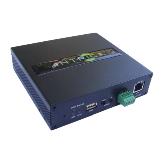
- Page 1 ONVIF 1080P60 H264 Video Decoder 1080p60&HD&Decoder& H.264&Decoder! User Manual ver.1.0...
- Page 2 Safety Precaution We appreciate you purchasing video server. Before installing the product, please read the following with care. • Make sure to turn off the power before installing the video server. • Do not install under the direct sunlight or dusty areas. •...
- Page 3 1. Introduction About this manual This user manual provides information on installation setup and operation of the video server, as well as troubleshooting tips. FEATURES This Video Decoder is an IP Decoder for various forms of video streaming (RTSP MPEG TS RTMP ONVIF) Supporting HDMI 3G HD-SDI and Composite video outputs.
- Page 4 Product and Accessories POWER ADAPTER AND CABLE QUICK START MANUAL BRACKETS SCREWS...
-
Page 5: System Connections
SYSTEM CONNECTIONS Video Decoder operates in one mode; Decoder Video server systems can be connected in either 1 to 1 fashion where one encoder is connected to one decoder or 1 to many fashion where one encoder is connected to many decoders. Following charts shows data status of video, audio and serial data. -
Page 6: Multicast Mode
In this configuration, a site can be monitored from many remote centre locations. Maximum connections would be limited by the network bandwidth. Functionally, the VMS (Video Management System) software can replace the decoder. MULTICAST MODE In the network supporting multicast mode, if multicast is setup as a system protocol, you can use bandwidth efficiently regardless of the number of decoders. -
Page 7: Installation
2. Installation Check if it works Once the power is supplied to the Decoder it will start booting. The system will boot up to an operating mode after approximately 40-60seconds. The green LED on the Ethernet port will flash indicating the system is ready. -
Page 8: Description Of Led
DESCRIPTION OF LED System status can be monitored with LED display. State Description Power off Power on Green blinking Normally operating STATUS System failure: Needs diagnostics No connection to remote system Connected to the remote system Green LINK Decoder only: trying to connect Red blinking Illegal connection (unsupported Orange... -
Page 9: System Operation
3. System Operation REMOTE VIDEO MONITORING There are two ways to monitor video when the centre system and IP camera / Decoder are connected. In order for proper operation, an IP address must be set accordingly. Please refer to True Manager Manual enclosed with product for further details. -
Page 10: Video Select
VIDEO SELECT Select the video stream to be viewed: primary, secondary, tertiary or quartic streaming. This camera is capable of dual streaming; primary streaming and secondary streaming. Video will be displayed according to the resolution set on video configuration. If dual streaming (“Use Dual Encode”... -
Page 11: Ptz Control
PTZ CONTROL (OPTICAL ZOOM & DIGITAL ZOOM BUILT-IN THE CAMERA Control PTZ and PTZ Control Panel is used for controlling external PTZ devices when external PTZ devices are connected through serial port. It is possible to make zooming control by Zoom in/out buttons of PTZ control panel (in order to use digital zoom, select Digital Zoom On in camera tab). - Page 12 SENSOR INPUT AND ALARM OUTPUT Display the status of the sensor in real time. This camera supports one sensor input. When the sensor of the camera is working, the sensor light turns red Operate the alarm device by pressing the number icon. This camera supports one alarm output. A number icon indicates status of the alarm device.
-
Page 13: Display Buffer
DISPLAY BUFFER Set the number of video frames to be buffered before being displayed on web browser. Larger value results in smoother video by sacrificing the latency. A setting of 10 ~ 15 frames can be used generally for most situations. -
Page 14: Video And Audio
VIDEO & AUDIO Information The information provides current information regarding the settings for Video and Audio. Audio... -
Page 15: Audio Source
AUDIO SOURCE Select the audio source: Analog stereo ALGORITHM Select the audio algorithm: G.711 or AAC. G.711 and AAC from client to server direction are supported. Thus, bidirectional audio communication is supported. SAMPLE RATE The camping rate defines the number of samples per unit of time taken from a continuous signal to make a discrete signal. -
Page 16: Output Format
OUTPUT FORMAT Select the format of output when Enable Preview is selected. BUFFERING Set the number of video frames to be buffered. Larger value results in smoother video by sacrificing the latency. A setting of 10 ~15 frames can be used generally for most situation. NETWORK IP &... - Page 17 LOCAL Select the IP mode: Fixed IP or DHCP. Depending on the selected modem further configuration items come as follows; IP Mode Selection Description Local IP Fixed IP Address Local Gateway Gateway IP Address Fixed IP Local subnet Subnet Mask DHCP Please ask IP address information from ISP provider or Network Manager.
- Page 18 Multicast The Multicast menu is used for configuring the multicast IP address to which media stream is delivered when a client such as a decoder, VMS or NVR software is connected in multicast mode. The multicast IP address selection range is between 224.0.0.0 and 239.255.255.255. The selection can be used only when media protocol is set to Multicast.
- Page 19 Remote: This is where you setup the details of the Camera or Encoder you wish the Decoder to Decode. Remote type Normal: Normal connection with Antrica IP Cameras via base port. RTSP: RTSP connection with RTSP stream via RTSP port. RTMP: RTMP connection with RTMP stream via RTSP port.
- Page 20 UPNP By the setting UPNP to on, it allows the discovery by clients according to UPNP (Universal Plug and Play) protocol. Zeroconf By setting Zeroconf to ON, it allows the discovery by the clients according to zeroconf protocol. WS Discovery Discovery function based on web service is enabled.
- Page 21 Simple Network Management Protocol (SNMP) is used by network management systems to communicate with network elements. SNMP lets TCP/IP-based network management client use a TCP/IP-based internetwork to exchange information about configuration and status of the nodes. SNMP can also generate trap messages used to report significant TCP/IP events asynchronously to interested clients.
- Page 22 Check IP Disable If ‘Check IP Disable’ is selected, it will skip to check its own IP. in fixed IP mode, the set IP will be registered on DDNS server. in DHCP mode, dynamically assigned IP will be registered on DDNS server. Normally Check IP Disable should be unchecked in order to obtain public IP in the network.
- Page 23 Connecting Client IP Addresses that are currently connected to system are listed. (1) indicates Decode List: This allows the decoder to cycle through pre set lists of camera URLs and display them at pre set times or remote control . Type in the camera URLs and the time you wish each camera to de displayed for.
- Page 24 Notification Local When a decoder instead of a PC client is connected to an ip camera, one system becomes a local system and the other a remote system (Generally a system which is being used by the users is called Local system). Then, actions for events can be configured for events from the remote system as well as when a sensor device in remote (site) IP camera is triggered.
- Page 25 Alarm Set the duration of alan or beet activation in case of an event. If it is set to continuous, it will be in active state until the operator resets it manually. Device Information The information provides current serial communication status.
- Page 26 Serial Serial Protocol - There are two serial ports, RS-232, RS-422/485 in video server. Select RS-422 or RS-485 in RS-422/485 port. Serial Port Configuration: The serial ports can be configured as follows. Each of the serial ports-configurations must be same as the connecting device Mode Selection 2400, 4800, 9600, 19200, 38400, 57600, 115200...
- Page 27 • Preset Max 128 preset positions can be defined. Select Preset Number: Select an entry in the list to be assigned to current camera position. Focus Mode: Select the focus mode after preset Goto is executed. • Do not change: current focus position saved when preset set •...
- Page 28 • User User List User can be registered and privilege level of a user can be specified. User configuration is allowed only to admin user. Max 16 users can be registered and each user can have one of four privileges. Privilege Allowed Operations Remarks...
- Page 29 Enter User ID and password (Up to 15 characters) and select Privilege Level. Delete User Select the User to be deleted and press Delete button Change Password Press Modify Password button. The following window will appear. Login Policy Login Policy Skip Login provides for convenient access to the server when authentication is not required.
- Page 30 • System Information System information Followed network information is displayed (Read only) • Model Display the model name. • Version Display the current firmware version. • Mac Address Display the MAC address of the camera. In case the camera is registered at DDNS server, the MAC address is used in DDNS registration.
- Page 31 Upgrade & Reboot Firmware Version: Display the current firmware version Upgrade : To upgrade firmware; 1. Press Browser button to select a firmware file from PC 2. Press Firmware Upgrade button to start upgrading. 3. A message for showing status (downloading / upgrading) will be displayed. Do not turn the camera off during upgrading.
- Page 32 Reboot Do not press Reboot unless server needs a reboot. Factory Reset All settings including User Accounts and logs are cleared. Factory Reset Except Network Settings All settings except for current network settings are changed to the default value. Time Start Time The latest the camera’s booting date and time.
- Page 33 The Network Time Protocol (NTP) is a protocol for synchronizing the clocks of computer systems over packet-switched, variable-latency data networks. It is designed particularly to resist the effects of variable latency by using a jitter buffer. System ID System ID Enter System ID that is used as a camera title.
- Page 34 1. Both system ID and Time are displayed. 2. Either system ID or Time can be displayed. When both are enabled, System ID is displayed. 3. No items are displayed. This is because video area is too small to display OSD text in large text. User defined OSD You can enter any text you like independent.
- Page 35 • Appendix A: Sensor and Alarm Port Sensor Port Terminal Type Voltage Rating: 150VAC Current Rating: 2A Colour: Red Sensor Signal Input Type No Contact Signals Connection to External Device Alarm Port Terminal Type Voltage Rating: 150VAC Current Rating: 2A Relay Type Contact Rating: 1A 30VDC Switching Power: Max 30W 62.5VA...
- Page 36 Switching Voltage: Mac 60VDC Alarm Signal Output Type NO/NC Contact Signals Connection to External Device Appendix B: Serial Port RS-232 Port Port Type 3 Pin Pin Arrangement ...
- Page 37 RS-422/485 Port Port Type 4 PIN PIN Diagram...
Need help?
Do you have a question about the ANT-36000A and is the answer not in the manual?
Questions and answers