Table of Contents
Advertisement
Quick Links
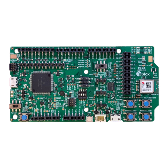
EVK-NORA-B1
Evaluation kit for NORA-B1 series modules
User guide
Abstract
This document describes how to set up the EVK-NORA-B100, EVK-NORA-B106, EVK_NORA-B126
and EVK_NORA_B120 evaluation kits to evaluate the NORA-B1 series modules. It also describes
the different options for debugging and the development capabilities included in the evaluation
board.
UBX-20030319 - R06
C1-Public
www.u-blox.com
Advertisement
Table of Contents

Related Manuals for Ublox EVK-NORA-B1


Summary of Contents for Ublox EVK-NORA-B1
- Page 1 EVK-NORA-B1 Evaluation kit for NORA-B1 series modules User guide Abstract This document describes how to set up the EVK-NORA-B100, EVK-NORA-B106, EVK_NORA-B126 and EVK_NORA_B120 evaluation kits to evaluate the NORA-B1 series modules. It also describes the different options for debugging and the development capabilities included in the evaluation board.
-
Page 2: Document Information
EVK-NORA-B1 - User guide Document information Title EVK-NORA-B1 Subtitle Evaluation kit for NORA-B1 series modules Document type User guide Document number UBX-20030319 Revision and date 24-Aug-2022 Disclosure restriction C1-Public Product status Corresponding content status In development / Objective specification Target values. Revised and supplementary data will be published later. -
Page 3: Table Of Contents
EVK-NORA-B1 - User guide Contents Document information ..........................2 Contents ................................3 Product description ..........................4 1.1 Key features ..............................4 1.2 Items included in kit............................ 5 1.2.1 EVK-NORA-B100 kit contents ......................5 1.2.2 EVK-NORA-B106 kit contents ......................5 1.2.3 EVK-NORA-B120 kit contents ......................5 1.2.4 EVK-NORA-B126 kit contents ...................... -
Page 4: Product Description
EVK-NORA-B1 - User guide Product description The EVK-NORA-B1 evaluation kit provides stand-alone use of the NORA-B1 series module featuring the Nordic Semiconductor nRF5340 dual-core RF System on Chip (SoC). The evaluation kit provides a great starting point for almost any Bluetooth® 5.2 Low Energy (LE), Thread, or Zigbee project. -
Page 5: Items Included In Kit
EVK-NORA-B1 - User guide 1.2 Items included in kit 1.2.1 EVK-NORA-B100 kit contents • EVK-NORA-B10 evaluation board with NORA-B100 module • Micro-USB cable • NFC antenna • 2.4 GHz U.FL antenna kit • 10-pin SWD programming cable, 2x5 headers on 1.27 mm centers ☞... - Page 6 EVK-NORA-B1 - User guide Tool Description Nordic Semiconductor’s nRF Connect extension pack turns VS Code into a complete IDE for developing applications for NORA-B1 and other Nordic Semiconductor based u-blox modules. This includes an interface to the compiler and linker, an RTOS-aware debugger, a seamless interface to the nRF Connect SDK and a serial terminal among other useful tools.
-
Page 7: Hardware Description
EVK-NORA-B1 - User guide Hardware description Design files in Altium, PDF, and Gerber formats for EVK-NORA-B1 PCBs may be requested from your local u-blox support team. 2.1 Power EVK-NORA-B1 has six possible power sources, as described below: Number Source Description... -
Page 8: High-Voltage Mode (Evk-Nora-B10 Only)
EVK-NORA-B1 - User guide 2.1.2 High-voltage mode (EVK-NORA-B10 only) ☞ The HV mode switch, SW1, in the schematic is labeled “Module power” on the silk screen. With the power switch in the ON position, and the HV mode switch in the HV (high-voltage) position, NORA-B10 is powered by VMODH. -
Page 9: Reset
EVK-NORA-B1 - User guide 2.2 Reset The EVK-NORA-B1 provides a configurable hardware reset to the NORA-B1 module. The Reset button can be configured to connect to an input on the interface IC or to directly connect to nRESET signal in the module. -
Page 10: Leds
EVK-NORA-B1 - User guide Figure 4: Schematic – user buttons 2.4 LEDs User LEDs are provided on the evaluation board – two red and two green. An RGB LED is also included and this can be enabled by changing the position of JLED1. -
Page 11: Serial Communication
EVK-NORA-B1 - User guide 2.5 Serial communication The evaluation board allows for easy serial communication with the NORA-B1 module and a connected computer. The J-Link debug interface IC provides three virtual COM port (VCP) devices: • The first (VCOM0) is used to obtain debug output and communicate with the network core. -
Page 12: Khz Low Frequency Clock
EVK-NORA-B1 - User guide Figure 6: UART level shifters and disable switches ☞ Figure 6 reflects Rev D and Rev E hardware versions. ☞ For Rev C or earlier hardware versions, applications need to map the following VCOM0 handshake signals: VCOM0_RTS = P0.12... -
Page 13: Nfc Connector
EVK-NORA-B1 - User guide If an internal LF clock source is used, the crystal can be removed from the circuit by opening jumpers J16 and J19. Soldering across the normally open position connects XL1 and XL2 to the EVK headers. -
Page 14: Current Sensing Headers
Any current sense resistor can be bypassed by soldering the respective jumper: JMOD, JSHD, or JHV. The default hardware configuration does not require any modification of the current sense headers for the EVK-NORA-B1 to perform properly. ☞ Only current flowing through VMOD into the module is measured; current sunk through GPIO pins is not measured. -
Page 15: External Segger J-Link™ Debug Interface
• Connect EXT_SWDIO to SWDIO and EXT_SWCLK to SWDCLK on the target NORA-B1 module. • (Optional) Connect EXT_SWO and/or nEXT_RESET on the target NORA-B1 module. • Connect external power to the target hardware, and then connect the EVK-NORA-B1 to USB. ☞... -
Page 16: Qspi
EVK-NORA-B1 - User guide 2.11 QSPI A 64 Mbit Quad SPI (MX25R6435F) flash is available on the EVK-NORA-B1. This memory can be used for execute-in-place (XIP) directly from the flash as well as from general data storage. Figure 11: Quad SPI flash 2.12 GPIO jumpers... -
Page 17: Header Pin-Out
NORA-B12 module on the PCB and N/C on J2. ⚠ The I/O pins of the EVK-NORA-B1 are not 5 V tolerant. Arduino Uno® style shields must be configured to use +3.3 V DC (VSHLD) as the I/O voltage reference. - Page 18 EVK-NORA-B1 - User guide Table 9 – Table 11 describe the pin assignments of each header. Pin name nRF5340 Function P1.03 P1.03 GPIO/TWI P1.02 P1.02 GPIO/TWI P0.27 P0.27 GPIO/AIN6 – Ground P1.15 P1.15 GPIO P1.14 P1.14 GPIO P1.13 P1.13 GPIO P1.12...
- Page 19 EVK-NORA-B1 - User guide Pin name nRF5340 Function P0.11 P0.11 GPIO/TRACEDATA0/CSN P0.12 P0.12 GPIO//TRACECLK/DCX P0.13 P0.13 OPEN/GPIO/QSPI DIO0 P0.14 P0.14 OPEN/GPIO/QSPI DIO1 P0.15 P0.15 OPEN/GPIO/QSPI DIO2 P0.16 P0.16 OPEN/GPIO/QSPI DIO3 P0.17 P0.17 OPEN/GPIO/QSPI CLK P0.18 P0.18 OPEN/GPIO/QSPI CSN P0.19 P0.19 GPIO P0.20...
- Page 20 EVK-NORA-B1 - User guide Pin name nRF5340 Function P1.14 P1.14 GPIO – +5.0 V USB Power P1.15 P1.15 GPIO P1.13 P1.13 GPIO RESET nRESET nRESET – Ground Table 14: Header J15 Pin name nRF5340 Function VSHLD – +3.3 V Shield Power VSHLD –...
-
Page 21: Application Development
EVK-NORA-B1 - User guide Application development Developing application code for the EVK-NORA-B1 requires an Internet connection and installation of certain tools – primarily Microsoft Visual Studio Code (VS Code) [15] and nRF Connect for Desktop [11]. nRF Connect for Desktop is used to manage the nRF Connect SDK installation as well as provide additional utilities. -
Page 22: Install Nrf Connect Sdk
EVK-NORA-B1 - User guide The Bluetooth Low Energy, Direct Test Mode, Power Profiler, Programmer and RSSI Viewer utilities provided through nRF Connect are optional, though they are useful for application development. 3.2.1 Install nRF Connect SDK Installation of the nRF Connect SDK on Windows uses the Toolchain Manager utility. -
Page 23: Board Support Package
All core options are contained in a single BSP folder. u-blox has submitted an application to include the EVK-NORA-B1 BSPs into the mainline Zephyr RTOS distribution. In the interim, the package is already available for download from the u-blox GitHub repository [3]. - Page 24 EVK-NORA-B1 - User guide 1. Select the “Create a new application” option. Figure 18: Create a new application 2. At the next screen, confirm the correct SDK version and Toolchain. At “application location”, select a local working directory. At “application template”, select “nrf/samples/Bluetooth/peripheral_lbs”...
- Page 25 EVK-NORA-B1 - User guide 4. Open the NRF Connect panel by clicking on the icon in the left column. Figure 20: nRF Connect for VS Code sidebar 5. Under “Applications / peripheral_lbs”, click the link to create a build configuration.
- Page 26 EVK-NORA-B1 - User guide 6. At the next screen, select the board “ubx_evknorab10_nrf5340_cpuapp” or “ubx_evknorab12_nrf5340_cpuapp”, depending on which board is in use, and optionally enable debug options. Click on Build Configuration. Figure 22: Build configuration - select board The application will be configured and compiled, ready to flash onto the EVK.
-
Page 27: Test The Application
EVK-NORA-B1 - User guide 7. In the “Actions” section, click “Flash”. Figure 23: J-Link connection and board flashing At this point, the peripheral_lbs sample is running. LED1 blinks at 1 second intervals to indicate that the module is advertising with the name Nordic_LBS. - Page 28 EVK-NORA-B1 - User guide Connect to Nordic_Blinky or Nordic_LBS; notice EVK LED 2 turn on solid. On the mobile app, swipe left to show the Services dialog. Figure 25: nRF Connect connection information dialog In the Button State service, tap the triple-down-arrow icon to enable Bluetooth LE notifications.
- Page 29 EVK-NORA-B1 - User guide In the LED State service, tap the up-arrow icon to display the Write Value dialog. Figure 27: Write to LED State service Figure 28: Write value to change EVK LED Try different one-byte values. A value of turns off LED 3.
-
Page 30: Appendix
EVK-NORA-B1 - User guide Appendix A Glossary Abbreviation Definition Arm (Advanced RISC Machines) Holdings Central Processing Unit Clear To Send Direct Current DC-DC DC to DC converter Device Firmware Update Evaluation Kit FICR Factory Information Configuration Register GPIO General Purpose Input / Output... -
Page 31: Related Documentation
EVK-NORA-B1 - User guide Related documentation NORA-B1 data sheet, UBX-20027119 NORA-B1 system integration manual, UBX-20027617 u-blox GitHub repository u-blox-sho-OpenCPU Nordic Semiconductor nRF5340 product specification Nordic Semiconductor nRF Connect SDK documentation Nordic Semiconductor nRF Connect SDK working with nRF53 series Nordic Semiconductor...
Need help?
Do you have a question about the EVK-NORA-B1 and is the answer not in the manual?
Questions and answers