Table of Contents
Advertisement
Quick Links
C099-F9P
Application board (rev. E)
User guide
Abstract
The C099-F9P board enables customers to evaluate RTK operation with the ZED-F9P high precision
GNSS receiver. The board provides short-range wireless connection via Bluetooth® or Wi-Fi for
receiving correction data and logging via wireless connectivity.
UBX-18063024 -
R16
C1-Public
www.u-blox.com
Advertisement
Table of Contents

Related Manuals for Ublox C099-F9P


Summary of Contents for Ublox C099-F9P
- Page 1 Application board (rev. E) User guide Abstract The C099-F9P board enables customers to evaluate RTK operation with the ZED-F9P high precision GNSS receiver. The board provides short-range wireless connection via Bluetooth® or Wi-Fi for receiving correction data and logging via wireless connectivity.
-
Page 2: Document Information
C099-F9P-0-03 Mass production C099-F9P-1-03 It is recommended to check the ZED-F9P firmware version on the C099-F9P Application board, and update to the last released version if needed, for more details on ZED-F9P firmware update procedure see section 7.1. u-blox or third parties may hold intellectual property rights in the products, names, logos and designs included in this document. -
Page 3: Table Of Contents
Contents ................................3 Introduction ............................. 5 1.1 Package contents ............................6 1.2 Additional sources of information ......................6 C099-F9P quick start ........................... 7 2.1 Starting up ..............................7 C099-F9P description .......................... 9 3.1 Component overview ..........................9 3.2 Component identification ......................... 9 ZED-F9P status LEDs ........................11... - Page 4 Reference station ODIN-W2 UDP client.txt ................39 F9P Stationary Base config C99.txt ..................... 39 F9P Rover config C99.txt ......................... 40 H C099-F9P antenna specification ....................40 H.1 Wi-Fi/Bluetooth antenna specification ..................40 ODIN-W2 firmware upload via JTAG .................... 41 Mechanical board dimensions ......................42 C099-F9P schematics ........................
-
Page 5: Introduction
C099-F9P - User guide Introduction The C099-F9P board is a convenient tool that allows customers to become familiar with the u-blox ZED-F9P high precision GNSS module. The board provides facilities for evaluating the product and demonstrating its key features. The C099-F9P application board offers: •... -
Page 6: Package Contents
Quick start guide • USB-to-DC plug adapter cable Figure 1: C099-F9P board and antennas 1.2 Additional sources of information Prior to using the board, it is useful to download the appropriate evaluation software and keep handy the documents listed in the Related documents section. -
Page 7: C099-F9P Quick Start
Device Manager. Set the baud rate to 460800 baud. See section 4.3.1 for detailed instructions. • The time pulse LED on the C099-F9P board blinks in blue once the ZED-F9P has obtained valid time information. Figure 3 below shows a typical u-center view with active satellite signal levels. - Page 8 C099-F9P - User guide • Eventually, the status changes to 3D/DGNSS/FIXED and the RTK LED shows a steady green light. Figure 3: u-center showing a view of the ZED-F9P default operation UBX-18063024 - R16 C099-F9P quick start Page 8 of 43...
-
Page 9: C099-F9P Description
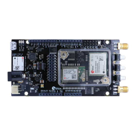
C099-F9P description 3.1 Component overview C099-F9P houses the ZED-F9P RTK high precision positioning module and an ODIN-W2 module for wireless short-range communications. An FTDI component provides dedicated COM port connections with the ZED-F9P and ODIN-W2 modules via a USB connector. - Page 10 C099-F9P - User guide GNSS antenna connector Wi-Fi/Bluetooth antenna connector ZED-F9P multi band GNSS RTK module ODIN-W2 multi-radio module J2, J3, J8, J9 Arduino Uno connectors DC power jack Battery connector USB (ZED-F9P USB and UART, ODIN-W2 UART ports) Figure 5: Main components and USB ports...
-
Page 11: Zed-F9P Status Leds
C099-F9P - User guide ZED-F9P and ODIN-W2 reset button ZED-F9P safeboot button ODIN-W2 switch 0 interrupt button ODIN-W2 activity LED GNSS LEDs: TP, RTK, Geofence Battery charger LED Battery incorrect polarity indicator Figure 6: Switches and LEDs ☞ The microSD card functionality is not supported by the currently released Mbed firmware for ODIN-W2. -
Page 12: Odin-W2 Activity Led
Table 1: ODIN-W2 Mbed FW LED activity states and colors ODIN-W2 activity LED Figure 8: ODIN-W2 activity LED position on C099-F9P board C099-F9P Jumpers The J4 connector provides options for ZED-F9P UART multiplexing. Table2 summarizes the main jumper options. - Page 13 PIN: 4: GROUND PIN 1: V_CURMEAS PIN 1: V_CURMEAS PIN 1 PIN 2: 5V MAIN PIN 2: 5V MAIN Figure 9: C099-F9P Jumper PIN details Jumper purpose Description V_CURMEAS MODE Current Measurement ODIN UART3 MODE Enable ZED-F9P RXD connection to ODIN UART3 (ODIN TXD3 -> ZED-F9P RXD) UART1 MODE Enable ZED-F9P RXD connection to ODIN UART1 (ODIN TXD ->...
-
Page 14: Using C099-F9P
C099-F9P - User guide Using C099-F9P The ZED-F9P module is shipped with the latest HPG firmware. Check the latest ODIN-W2 Mbed FW availability and information on the FW update procedures in section 7 Firmware update. 4.1 Powering the board The board can be powered from a variety of sources: •... -
Page 15: Non-Wireless Operation
4.2 GNSS RF input The C099-F9P board should be used with the antenna supplied with the kit. If another active antenna is used, be aware that the RF input has a bias output designed to supply 3.3 V DC with a 70-mA maximum current load. -
Page 16: User Interfaces
Figure 12: The supplied GNSS multi-band antenna 4.3 User interfaces C099-F9P has a number of fixed connection options besides the wireless modes. There is also an additional Arduino R3 / Uno interface for external host connection. The USB connector on the board provides connection via an on-board hub providing: •... -
Page 17: Command Line Interface Of Odin-W2
C099-F9P - User guide Figure 14: u-center view with ZED-F9P connected Additional UBX protocol messages can be enabled to view additional information in u-center. For example, the following are typical messages the user can poll or enable for periodic update. -
Page 18: Persistent Odin-W2 Settings
C099-F9P - User guide Figure 15: CLI help command Figure 16: Example RPC syntax By typing the help command as in Figure 15, ODIN-W2 displays all available user commands with a short description. The CLI embodies character echo with limited text edit functions. Misspelled commands are replied to with a list of supported commands. -
Page 19: Rover Operation Using Ntrip
A suitable host is a PC with internet access. A host runs an NTRIP client and streams RTCM corrections to C099-F9P through a UART or Bluetooth connection. Messages transmitted through a Bluetooth or Wi-Fi link are forwarded to I2C bus and vice versa. The user is advised to enable desired messages in both UART and I2C interfaces in ZED-F9P. -
Page 20: Mobile Hosting
5.2 Mobile hosting A portable rover option is offered by an Android application that utilizes a Bluetooth connection to a single C099-F9P. An example application is provided by Lefebure and it is available from Google Play Store: https://play.google.com/store/apps/details?id=com.lefebure.ntripclient. The application integrates an NTRIP client that forwards corrections received from a cellular or a wireless network to the Bluetooth interface. -
Page 21: Wireless Communication
• Next, perform a Bluetooth scan to find the C099-F9P board. Every C099-F9P has a predefined, unique Bluetooth name in BT_C099-F9P_XYZW format as shown in Figure 20. Figure 20: Windows 10 menu for adding a Bluetooth device ODIN-W2 as the pairing initiator •... -
Page 22: Server Spp Connection
COM port. Note that you can ignore the baud rate of the Bluetooth serial port on the host PC. Client SPP connection • To use the outgoing port (client port) on the host PC, set C099-F9P to server mode by issuing the following command: /bt_visible/run •... -
Page 23: Wi-Fi Connectivity
Wi-Fi access point and UDP server The C099-F9P RTK base can be set to operate as a Wi-Fi access point and UDP server to deliver RTCM corrections via a Wi-Fi link. For rover operation, C099-F9P can be configured either to Wi-Fi STA or Wi-Fi AP mode. - Page 24 Figure 23: Wi-Fi base and rover setup 6.3.1.2 Rover operation in Wi-Fi AP mode To connect to a C099-F9P rover via a Wi-Fi link, follow the configuration steps below: 1. Configure C099-F9P to Wi-Fi AP mode by using the CLI command in terminal: /mem_store/run wifi_ap 2.
-
Page 25: Wi-Fi Station And Udp Client
Typically, the Wi-Fi STA mode is applicable when two C099-F9Ps (base and rover) interconnect via a Wi-Fi link. Firstly, it is recommended to configure the base as instructed in section 6.3.1.1 Base operation in Wi-Fi AP mode. Secondly, the rover C099-F9P is set up to function in Wi-Fi STA and rover mode: 1. -
Page 26: Wireless Link Limitations
(yellow LED). If the disconnection is not intended, check the Wi-Fi interface on the host PC. Wi-Fi channel congestion can be avoided by changing the Wi-Fi AP channel on C099-F9P. Typically, channel congestion is experienced when the Wi-Fi connection indicators (e.g. LEDs) are OK but no data is received. - Page 27 C099-F9P - User guide uses its own Bluetooth stack. A device that is known to work is the ASUS USB-BT400 (USB 2.0). Once installed, use the Bluetooth virtual COM port assigned to this device and not the built-in Bluetooth interface.
-
Page 28: Firmware Update
7.1 ZED-F9P firmware update This section shows how to update the firmware and re-enable the configuration settings required for C099-F9P. There are two possible serial communication channels to update ZED-F9P: the UART1 and USB2.0 ports. 1. To update ZED-F9P, connect to u-center via USB to the COM port identified as ZED-F9P and poll MON-VER to view the installed firmware: see Figure 13 for the Device Manager COM port view. - Page 29 C099-F9P - User guide Figure 27: Selecting u-center Firmware image folder 3. At the top is the Firmware image file selection window. Click the button on the right of the window. This allows you to select the folder and file. Select the new firmware image bin file.
- Page 30 C099-F9P - User guide Figure 30: Setting ZED-F9P UART1 back to 460800 baud and saving it to flash memory UBX-18063024 - R16 Firmware update Page 30 of 43 C1-Public...
-
Page 31: Odin-W2 Firmware Update
4. Prior to firmware upload, ODIN-W2 must be started in safeboot mode. Proceed by placing a safeboot jumper and reboot C099-F9P. The locations of the safeboot pin header and the reset button are depicted in Figure 6. To confirm that ODIN-W2 started in safeboot mode, check that the ODIN-W2 activity LED remains off. - Page 32 ODIN-W2 in safe boot mode. Proceed by placing a safe boot jumper and reboot the C099-F9P. The location of the safe boot pin header and the reset button is depicted in Figure 6.
- Page 33 C099-F9P - User guide Once the connectivity software is uploaded successfully, the ODIN-W2 will be set with a baud rate of 115200 baud with hardware flow control enabled. You must change this to no hardware flow control and set the ODIN-W2 UART baud rate to 460800 to ensure sufficient link bandwidth.
- Page 34 Figure 40: Clicking AT Mode button Download a u-blox configuration file for the ODIN-W2 module. The “u-blox ODIN-W2 BT Rover.txt” file is the default configuration file shipped with the C099-F9P. See Appendix Error! Reference source not found. for configuration file resources.
- Page 35 The ODIN-W2 UART will now be set to 460800 baud in Data default mode. It will be ready for use again. Disconnect s-center from the ODIN-W2 port and power the C099-F9P off and on to ensure it will be using the new configurations as default.
-
Page 36: Arduino Header Connections
39 below. All the pin functions besides power are 3.3 V compliant. J9, Arduino D J3, Arduino B J8, Arduino C J2, Arduino A Figure 38: C099-F9P Arduino connectors Figure 39: C099-F9P Arduino R3 connections UBX-18063024 - R16 Arduino header connections Page 36 of 43 C1-Public... -
Page 37: Appendix
C099-F9P - User guide Appendix A Glossary Abbreviation Definition Command-line interface Firmware LiPo Lithium polymer NTRIP Networked transport of RTCM via internet protocol NVDS Non-volatile data storage Real time kinematic UART Universal asynchronous receiver transmitter User datagram protocol Universal serial bus... -
Page 38: D Rover Odin-W2 Access Point Udp Server.txt
C099-F9P - User guide ATS3=13 ATS4=10 ATS5=8 AT+UDCFG=0,1 AT&S1 AT&D0 ATE1 AT+UBTCFG=1,1 AT+UBTCFG=2,1 AT+UBTCFG=3,56602 AT+UBTCFG=4,127 AT+UBTCFG=5,0 AT+UBTCFG=6,0 AT+UBTCFG=7,2000 AT+UBTCFG=8,0 AT+UBTCFG=9,0 AT+UBTLECFG=1,1600 AT+UBTLECFG=2,2000 AT+UBTLECFG=3,7 AT+UBTLECFG=4,24 AT+UBTLECFG=5,40 AT+UBTLECFG=6,0 AT+UBTLECFG=7,2000 AT+UBTLECFG=8,5000 AT+UBTLECFG=9,48 AT+UBTLECFG=10,48 AT+UBTLECFG=11,24 AT+UBTLECFG=12,40 AT+UBTLECFG=13,0 AT+UBTLECFG=14,2000 AT+UBTLECFG=15,5000 AT+UBTLECFG=16,48 AT+UBTLECFG=17,48 AT+UBTLECFG=18,24 AT+UBTLECFG=19,40 AT+UBTLECFG=20,0... -
Page 39: E Reference Station Odin-W2 Udp Client.txt
C099-F9P - User guide AT+UMRS=460800,2,8,1,1,0 AT&D0 AT&W AT+CPWROFF E Reference station ODIN-W2 UDP client.txt Copy all the text below this line into a text file named “Base ODIN-W2 Station UDP client.txt”. AT+UWSCA=0,4 AT+UWSC=0,0,1 AT+UWSC=0,2,"UBXWifi" AT+UWSC=0,5,1 AT+UWSC=0,100,2 AT+UWSCA=0,1 AT+UWSCA=0,3 AT+UWCFG=1,0 AT+UMSM=1 AT+UDDRP=0,"udp://192.168.0.10:5003",2... -
Page 40: G F9P Rover Config C99.Txt
C099-F9P - User guide RAM CFG-MSGOUT-RTCM_3X_TYPE1124_USB 0x1 # write value 1 to item id 20910370 Flash CFG-MSGOUT-RTCM_3X_TYPE1124_USB 0x1 # write value 1 to item id 20910370 RAM CFG-MSGOUT-RTCM_3X_TYPE1230_USB 0x5 # write value 5 to item id 20910306 Flash CFG-MSGOUT-RTCM_3X_TYPE1230_USB 0x5... -
Page 41: Iodin-W2 Firmware Upload Via Jtag
FCC, IC, RED, MIC, NCC, KCC*, ANATEL, and ICASA Table 5: Wi-Fi/Bluetooth antenna ☞ The variant included in the C099-F9P kit has an SMA connector and has to be mounted on the corresponding antenna connector of the C099-F9P board if you wish to use Wi-Fi or Bluetooth connectivity. -
Page 42: J Mechanical Board Dimensions
C099-F9P - User guide J Mechanical board dimensions Figure 40: C099-F9P rev. E dimensions K C099-F9P schematics C099-F9P evaluation board schematics, UBX-22008807 UBX-18063024 - R16 Appendix Page 42 of 43... -
Page 43: Related Documents
Revision Date Name Comments 10-Jul-2018 ghun/byou Initial release 19-Oct-2018 byou Updates for the C099-F9P rev. B board revision. 8-Nov-2018 olep Updates for Mbed3 FW in ODIN-W2 1-Feb-2019 olep Updates for Wi-Fi and NVDS features in ODIN-W2 21-Feb-2019 olep Updated Arduino J9 schematics. Polarity requirement of the battery connector.
Need help?
Do you have a question about the C099-F9P and is the answer not in the manual?
Questions and answers