
Related Manuals for FISCHER NK10 H Series


Summary of Contents for FISCHER NK10 H Series
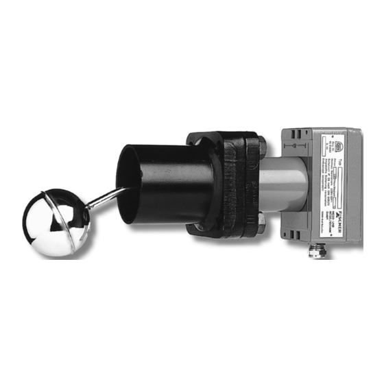
- Page 1 II 2G Ex ib c IIC T6 Gb DIN 4754 IEC 61508 II 2D Ex tb c IIIC T80 °C Db Operating manual NK10 ... H Fill Level Limiter for use in explosive areas Gas explosion protection Zone 1 and 2 Dust explosion zone 21 and 22...
- Page 2 Great care was taken when compiling the texts and illustrations; Nevertheless, errors cannot be ruled out. The company FISCHER Mess- und Regeltechnik GmbH will not accept any legal responsibility or liability for this.
-
Page 3: Table Of Contents
FISCHER Mess- und Regeltechnik GmbH Table of Contents Table of Contents 1 Safety guidelines......................4 1.1 General........................... 1.2 Personnel Qualification ......................1.3 Risks due to Non-Observance of Safety Instructions............. 1.4 Safety Instructions for the Operating Company and the Operator ......... -
Page 4: Safety Guidelines
1 | Safety guidelines FISCHER Mess- und Regeltechnik GmbH 1 Safety guidelines 1.1 General This operating manual contains basic instructions for the installation, operation and maintenance of the device that must be followed without fail. It must be read by the installer, the operator and the responsible specialist personnel be- fore installing and commissioning the device. -
Page 5: Unauthorised Modification
FISCHER Mess- und Regeltechnik GmbH Safety guidelines | 1 A professional single conformity inspection as per DIN EN 61010, section 1, must be carried out before the instrument can be re-commissioned. This inspec- tion must be performed at the manufacturer's location. Correct transport and storage of the instrument are required. -
Page 6: Pictogram Explanation
1 | Safety guidelines FISCHER Mess- und Regeltechnik GmbH 1.8 Pictogram explanation DANGER Type and source of danger This indicates a direct dangerous situation that could lead to death or serious injury (highest danger level). 1. Avoid danger by observing the valid safety regulations. -
Page 7: Product And Functional Description
FISCHER Mess- und Regeltechnik GmbH Product and functional description | 2 2 Product and functional description 2.1 Delivery scope • NK10 according to specification (see order code) • Operating Manual • Safety manual for SIL version 2.2 Intended use The NK10 fill level limiter is used in thermo-technical and process plants as a safeguard against the fill level falling below the lowest permissible level. -
Page 8: Function Diagram
2 | Product and functional description FISCHER Mess- und Regeltechnik GmbH WARNING Installation regulations The respective installation instructions must be observed for every application case. 2.5 Function diagram Fig. 1: Function diagram Swimmer Swimmer rod Metal bellows Test button Switch lever... -
Page 9: Installation And Assembly
FISCHER Mess- und Regeltechnik GmbH Installation and assembly | 3 3 Installation and assembly 3.1 Safety guidelines WARNING Non-observance of the following safety instructions Non-observance of the following safety instructions can lead to a dangerous situation, fatal injuries, series bodily harm or damage. -
Page 10: Electrical Connections
3 | Installation and assembly FISCHER Mess- und Regeltechnik GmbH NOTICE! Please check: • The swimmer must be able to move freely in the vertical direction! • Test the switching function using the test button. 3.4 Electrical connections • By authorized and qualified specialized personnel only. - Page 11 FISCHER Mess- und Regeltechnik GmbH Installation and assembly | 3 Recommend circuit breakers: These separation switch devices are available as accessories. Type Description Operating voltage MTL 5011 B 1-channel for contact 20 … 35 V DC MTL 5015 2-channels for contact 20 …...
-
Page 12: Commissioning
4 | Commissioning FISCHER Mess- und Regeltechnik GmbH 4 Commissioning 4.1 Safety guidelines WARNING Faulty device The instrument must be decommissioned and secured against inadvertent re- operation if a situation arises in which it must be assumed that safe operation is no longer possible. -
Page 13: Servicing
FISCHER Mess- und Regeltechnik GmbH Servicing | 5 5 Servicing 5.1 Maintenance WARNING Dust deposits The device must be cleaned with a damp cloth a regular intervals to prevent heat build-up. Cleaning intervals depend on the amount of local dust. -
Page 14: Technical Data
6 | Technical data FISCHER Mess- und Regeltechnik GmbH 6 Technical data 6.1 General Please also observe the order code here. 6.2 Application conditions 0.8 to 1.1 bar abs The EC type test is based on atmospheric conditions of 0.8 to 1.1 bar abs and -20°C to 60°C... -
Page 15: Switch Contacts
FISCHER Mess- und Regeltechnik GmbH Technical data | 6 6.3 Switch contacts 1 or 2 micro-switches with 1-pin changeover contact. WARNING Only for connection to certified intrinsically safe circuits in the igni- tion protection class Ex ib IIC. Highest values per electricity circuit:... -
Page 16: Construction Design
6 | Technical data FISCHER Mess- und Regeltechnik GmbH 6.6 Construction design Swimmer system Stainless steel 1.4571 Metal bellows Stainless steel 1.4571 Flange / counter-flange Stainless steel 1.0425 (P265GH) or 1.4571 Welding socket St.35.8 [1.0345 (P235GH)] Screws / nuts G 7258 / C35PbK Please note the material information in the dimensional drawings. - Page 17 FISCHER Mess- und Regeltechnik GmbH Technical data | 6 6.6.1.2 Flange DIN EN 1092-1 Type B1 Version Flange Port No. of material [Ø] [Ø] [Ø] holes NK102 1.0425 P265GH DN80 PN40 NK10G 1.4571 DN80 PN40 Fig. 5: Dimensional picture NK102 NK10G...
- Page 18 6 | Technical data FISCHER Mess- und Regeltechnik GmbH 6.6.1.3 Flange DIN EN 1092-1 Type C Version Flange Port No. of material [Ø] [Ø] [Ø] holes NK10F 1.0425 P265GH DN80 PN40 19.5 Fig. 7: Dimensional picture NK10F Version Flange Port No. of material [Ø]...
- Page 19 FISCHER Mess- und Regeltechnik GmbH Technical data | 6 6.6.1.4 Flange DIN EN 1092-1 Type G Version Flange Port No. of material [Ø] [Ø] [Ø] holes NK10H 1.4571 DN80 PN40 Fig. 9: Dimensional picture NK10H 6.6.1.5 Flange DIN EN 1092-1 Type D...
- Page 20 6 | Technical data FISCHER Mess- und Regeltechnik GmbH 6.6.1.6 Flange ANSI B16.5 Version Flange Port No. of material [Ø] [Ø] [Ø] holes NK10K 1.0425 P265GH 3‘‘ 150 lbs 192.5 152.4 22.8 19.1 NK10N 1.0425 P265GH 3‘‘ 300 lbs 209.5 168.1...
-
Page 21: Order Codes
FISCHER Mess- und Regeltechnik GmbH Order Codes | 7 7 Order Codes Code no. 10 11 12 Type Swimmer Flange material DIN EN 1092-1 Form B1 DN 65 PN40 1.0425 P265GH DIN EN 1092-1 Form B1 DN 80 PN40 1.0425... -
Page 22: Attachments
8 | Attachments FISCHER Mess- und Regeltechnik GmbH 8 Attachments 8.1 Declaration of Conformity Fig. 13: CE_EN_NK10_H_page1 22/40 BA_EN_NK10_H... - Page 23 FISCHER Mess- und Regeltechnik GmbH Attachments | 8 Fig. 14: CE_EN_NK10_H_page2 BA_EN_NK10_H 23/40...
-
Page 24: Type Testing Certificates
8 | Attachments FISCHER Mess- und Regeltechnik GmbH 8.2 Type testing certificates 8.2.1 Pressurised Vessel Directive 2014/68/EU Fig. 15: 8120501655 Type certificate NK 10 - 2022 24/40 BA_EN_NK10_H... - Page 25 FISCHER Mess- und Regeltechnik GmbH Attachments | 8 Fig. 16: 8119262687 Fischer Messtechnik Certificate Modul D-2021 rev_01 BA_EN_NK10_H 25/40...
- Page 26 8 | Attachments FISCHER Mess- und Regeltechnik GmbH 8.2.2 ATEX Guideline 2014/34/EU Fig. 17: BMP_94-9-EG_EN_TÜV 07 ATEX 553595_page1 26/40 BA_EN_NK10_H...
- Page 27 FISCHER Mess- und Regeltechnik GmbH Attachments | 8 Fig. 18: BMP_94-9-EN_DE_TÜV 07 ATEX 553595_page2 BA_EN_NK10_H 27/40...
- Page 28 8 | Attachments FISCHER Mess- und Regeltechnik GmbH Fig. 19: BMP_94-9-EG_EN_TÜV 07 ATEX 553595_page3 28/40 BA_EN_NK10_H...
- Page 29 FISCHER Mess- und Regeltechnik GmbH Attachments | 8 Fig. 20: BMP_94-9-EG_EN_TÜV 07 ATEX 553595_1ER_page1 BA_EN_NK10_H 29/40...
- Page 30 8 | Attachments FISCHER Mess- und Regeltechnik GmbH Fig. 21: BMP_94-9-EG_EN_TÜV 07 ATEX 553595_1ER_page2 30/40 BA_EN_NK10_H...
- Page 31 FISCHER Mess- und Regeltechnik GmbH Attachments | 8 8.2.3 DNV GL Certificate Fig. 22: DNVGL_TAA000020S_Page_1 BA_EN_NK10_H 31/40...
- Page 32 8 | Attachments FISCHER Mess- und Regeltechnik GmbH Fig. 23: DNVGL_TAA000020S_Page_2 32/40 BA_EN_NK10_H...
- Page 33 FISCHER Mess- und Regeltechnik GmbH Attachments | 8 Fig. 24: DNVGL_TAA000020S_Page_3 BA_EN_NK10_H 33/40...
-
Page 34: Din Certco Certification Din 4754-3
8 | Attachments FISCHER Mess- und Regeltechnik GmbH 8.3 DIN CERTCO Certification DIN 4754-3 Fig. 25: DIN_CERTCO_10F001_EN_Page_1 34/40 BA_EN_NK10_H... - Page 35 FISCHER Mess- und Regeltechnik GmbH Attachments | 8 Fig. 26: DIN_CERTCO_10F001_EN_Page_2 BA_EN_NK10_H 35/40...
-
Page 36: Sil Certificate
8 | Attachments FISCHER Mess- und Regeltechnik GmbH 8.4 SIL Certificate Fig. 27: 968_V_1298_00_22_de_en_el_page_1 36/40 BA_EN_NK10_H... - Page 37 FISCHER Mess- und Regeltechnik GmbH Attachments | 8 Fig. 28: 968_V_1298_00_22_de_en_el_page_2 BA_EN_NK10_H 37/40...
- Page 38 FISCHER Mess- und Regeltechnik GmbH Notes 38/40 BA_EN_NK10_H...
- Page 39 FISCHER Mess- und Regeltechnik GmbH Notes BA_EN_NK10_H 39/40...
- Page 40 Mess- und Regeltechnik GmbH Bielefelder Str. 37a D-32107 Bad Salzuflen Tel. +49 5222 974-0 Fax +49 5222 7170 www.fischermesstechnik.de info@fischermesstechnik.de Technische Änderungen vorbehalten. Subject to technical changes. Sous réserve de modifications techniques.
Need help?
Do you have a question about the NK10 H Series and is the answer not in the manual?
Questions and answers