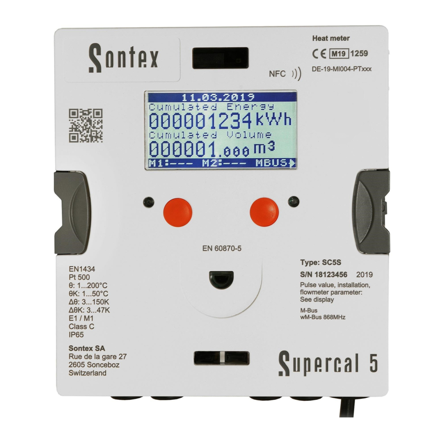
Sontex Supercal 5 - Thermal Energy Meter Installation Guide
- Installation manual (148 pages) ,
- Installation manual (4 pages)
Advertisement
- 1 Installation guidelines
- 2 Cable connection
- 3 Safety instructions
- 4 Function test
- 5 Pressure Loss Curve
- 6 Temperature sensors mounting
- 7 List of sensor pockets
- 8 Temperature sensors connections
- 9 Temperature sensor installation with cooling applications
- 10 Error messages
- 11 Communication options
- 12 Cooling liquids (Glycols)
- 13 Display
- 14 LCD control concept
- 15 LCD (Standard)
- 16 Commissioning Menu
- 17 Dimension of the Device
- 18 Conditions to comply with the directive 2014/32/EU (MID)
- 19 Manufacturer's notice
- 20 Security seals
- 21 Sealing
- 22 Further information
- 23 Technical support
- 24 Declaration of conformity
- 25 Documents / Resources
Installation guidelines
The static flow sensor and its calculator may only be operated within the conditions outlined on the identification plate, as well as within the technical specification! In the case of ignoring these default conditions, the manufacturer's responsibility is void and null.
The manufacturer is not liable for inappropriate installation and operation. Seals may not be removed and/or only by authorized persons. The country-specific, local regulations, as well as the manufacturer instructions, must be respected!
If the manufacturer's seal has been broken or damaged, the manufacturer cannot be made responsible for the change of the verified and meas-uring relevant data.
When using several heat meters in an installation unit, fair heat consumption measurement muss be chosen. All of them in the same types of device and installation positions
Before installation
- Check the design layout data of the installation.
- The pulse value of the calculator and the installation location must match the values indicated on the flow sensor, consult the identification plate!
- The permissible ambient temperature range of the calculator is 5 – 55ºC.
- The installation and project prescriptions must be followed.
- The readability of the calculator and also the identification plates must be followed.
Remarks on the correct installation
Conditions to comply with the directive 2014/32/EU (MID)
- The calculator is delivered as a heat meter as standard. If it is to be used as a cooling meter or as a combined cooling/heat meter, this must be specified when ordering. Other metrological parameters such as installation position or pulse value (Supercal 5 I only) as well as non-metrological parameters such as M-Bus address can be parameterised with the Superprog software before sealing. Please note that metrological parameters can no longer be changed after the calculator has been sealed.
- The cable between the flow sensor and the calculator cannot be extended.
- All wiring must be installed with a minimum distance of 300 mm from heavy voltage and high frequency cables.
- Radiated heat and interfering electrical fields close to the calculator must be avoided.
- In general, the calculator should be installed away from the cooling pipes.
- It has to be ensured that no condensed water can run along the wires into the calculator.
- If the danger of vibrations in the piping system exists, the calculator should be installed separately on the wall.
- For temperatures over 90°C the calculator must be installed apart from the flow unit.
- The flow sensor should be installed between two shut-off valves.
- The flow sensor must be mounted with the measuring head to the side
- The flow direction of the flow sensor must be respected (arrow on the flow sensor).
- Flush the pipe system before installing the flow sensors. To guarantee that no foreign particles remain in the pipe.
- The flow sensor should be mounted BEFORE any control valve to exclude any potential parasitic influences.
- During commissioning the pipe system must be purged. Air in the system of the flow sensor may affect the measurement.
- Use only new and appropriate sealing material.
- Water tightness of the different connections should be verified.
The Supercal 5 is a compact calculator and consists of the following two partial units:
- Measuring and calibrating-relevant upper part
- Lower part
The pulse values of the calculator and of the flow unit, as well as the resistance value of the temperature sensors (Pt500) must match. Compare the labels of the devices!
Cable connection
To connect the inputs and outputs the calculator's upper part must be removed. Shielded cables must be grounded with a strain relief!
| Terminal | connection type |
| 5, 6 | 2-wire direct connection, temperature high |
| 1, 5 and 6, 2 | 4-wire, temperature high |
| 7, 8 | 2-wire direct connection, temperature low |
| 3, 7 and 4, 8 | 4-wire, temperature low |
| 10 | (+) pulse inputs flow sensor 440 (white cable) |
| 11 | (-) pulse inputs flow sensor 440 (green cable) |
| 9 | Power supply of the flow sensor 440 (brown cable) |
| 50 | (+) Pulse input, additional pulse input 1 |
| 51 | (-) Pulse input, additional pulse input 1 |
| 52 | (+) Pulse input, additional pulse input 2 |
| 53 | (-) Pulse input, additional pulse input 2 |
| 16 | (+) Open collector-output 1 |
| 17 | (-) Open collector output 1 |
| 18 | (+) Open collector output 2 |
| 19 | (-) Open collector output 2 |
| 24 | M-Bus (polarity independent) |
| 25 | M-Bus (polarity independent) |

Grounding
It has to be guarantied that all grounding connections (line and power mains and chassis of the flow sensor) of the total installation are equipotential.
Power supply modules
The power supply modules are connected by means of a plug-in connector to the main board.
Power Supply at the Calculator
The Supercal 5 can be supplied with either battery or mains modules: D Battery 3,6 V, mains 24 V (12 VAC to 36 VAC or 12VDC to 42 VDC), mains 230 VAC (110 VAC to 230 VAC, 50/60 Hz).
These can be converted and retrofitted at any time.
The mains module is equipped with a backup battery already installed.
The electrical connection of the mains power supply modules
The electrical connection has to be done in accordance with valid standards, under consideration of local safety regulations and by an authorized person. The electrical main is to be made in such way that no hot parts (pipes etc. over 80°C) can be touched (danger with damaged isolation). Water contact of the electrical connection must be avoided.

Cable connections
Mains supply
110... 230 VAC

Cable connections
Mains supply
12...36 VAC / 12...42 VDC
Backup battery in the calculator upper part
The upper part of the calculator, which is relevant for calibration and measurement, is equipped with an A-cell battery. This serves as power supply for the LCD display when the upper part of the calculator is removed from the lower part or when no power supply is available. The battery has a service life of about 10 years in the backup function.
Safety instructions
The calculator is manufactured and tested according to EN 61010 safety control for measuring units and left the factory in perfect safety tech-nical condition. To maintain this status and to guarantee the safe operation of the calculator, the user must respect the instructions contained in this document. When opening covers or removing parts, parts under power can be accessed. Further connection terminals can be under power. All repair and maintenance work may be only implemented by a trained and authorized specialist. If the housings and/ or the connect-ing cable show any damage, the calculator unit should be disconnected and secured against accidentally reset up – put in operation. General-ly, avoid an installation situation with an accumulation of heat above average. An above-average heat build-up affects substantially the lifetime of the electronic components.
Heat meters are measuring devices and must be handled with care.
To protect the unit against damage and contamination, the packing should be only removed at the moment of installation.
For cleaning just use water moistened cloth and no solvent.
The connecting and connection cable may not be fastened on the pipe and under no circumstances be isolated together with the pipe.
Function test
After opening the shut-off valves, the system must be checked for leaks. Then, by repeatedly pressing the user button, various operating parameters such as flow rate, output and flow and return temperature can be read on the LCD display of the calculator. If modules are installed, this is also shown on the LCD display (M1:,M2:). With the Superprog Windows and Superprog Android software, you can read additional information from the unit.
All parameter displays are used to check the thermal energy meter or to adjust the system. It must be checked that the regulated flow of the system does not exceed the maximum permitted flow of the meter. A commissioning protocol via the optical interface with the readout software is recommended for a comprehensive functional check.
Pressure Loss Curve

Temperature sensors mounting
The temperatures indicated on the identification plate of the temperature sensors are to be observed. The temperature sensors are always paired. Only matched pairs are supplied and may not be separated, extended or shortened, since this affects the measuring accuracy. With temperature sensor pairs with a cable length longer than 3 m, we exclusively recommend the use of shielded temperature sensor pairs. In this case, the shields must be installed correctly. Temperature sensors with protection pockets must be inserted up to the stall – and fixed afterwards. With unequal cable lengths or longer than 6 m we recommend exclusively the use of four-wire technology. The temperature sensors can be installed alternatively in protection pockets or directly in the heating and/or cooling agent however always both in the same way. Asymmetrical mounting, one sensor direct the other with pockets, isn't permitted. The measuring tip of the temperature sensor part must be positioned in the center of the cross section of the pipe.
DN15, 20, 25
Installation in T-fitting

Temperature sensor perpendicularly to the axis of the piping in the same level
 DN 50
DN 50
Installation with welding sleeve 90º

Temperature sensor axle coincide with the tubing axle
DN 50
Installation with welding sleeve 45º

Temperature sensor measuring element submerged onto the tubing axle
DN 65 - 250
Installation in pipe

Temperature sensor axle perpendicularly to the tubing axle.
List of sensor pockets
| Temperature sensor | Versions | Part number | Material | Temperature range | |
| Ø 6 x 31mm | Pt500 | G3/8" | 0460A202 | Brass | 0... 100°C |
| Ø 6 x 31mm | Pt500 | G1/2" | 0460A206 | Brass | 0... 100°C |
| Ø 6 x 85mm | Pt500, DIN | G1/2" | 0460A207 | Stainless | 0... 150°C |
| Ø 6 x 134mm | Pt500, DIN | G1/2" | 0460A208 | Stainless | 0... 150°C |
| Ø 6 x 174mm | Pt500, DIN | G1/2" | 0460A209 | Stainless | 0... 150°C |
The resonance frequencies of the protection pockets are outside of the flow velocities at maximum flow (qs).
Temperature sensors connections
2 wires cable sensor
5/6 temperature high
7/8 temperature low

4 wires sensor with
2 wires integrator
5/6 temperature high
7/8 temperature low

4 wires sensor with
4 wires integrator
1/5 + 2/6 temperature high
3/7 + 4/8 temperature low

Wire cross section for head sensors ≥ 0,5 mm2 (EN 1434-2)
Temperature sensor installation with cooling applications
The isolation may be made only up to the temperature sensor screw connection.

 The screw connection of the temperature sensors may in no case be isolated with. This applies even if the temperature sensor is installed directly in the flow sensor.

Error messages
The Supercal 5 indicates occurring errors by displaying on the LCD the Err-sign together with a numbered code. If several errors occur at the same time, the numbers of the error codes are added.
| 1 | Temperature reference 1 A/D: A cable of the temperature sensor is interrupted or not connected. |
| 2 | Temperature reference 2 A/D: A cable of the temperature sensor is interrupted or not connected. |
| 4 | Temperature reference 1 A/D: A cable of the temperature sensor is conected but its value can not be read out. |
| 8 | Temperature reference 2 A/D: A cable of the temperature sensor is connected but its value can not be read out |
| 16 | Temperature sensor 1 < = min. Range error |
| 32 | Temperature sensor 1 > = max. Range error |
| 64 | Temperature sensor 2 < = min. Range error |
| 128 | Temperature sensor 2 > = maxß. Range error |
| 512 | The flow rate is higher than 1,5 qs |
| 1024 | The SC5 is open |
| 2048 | Power outage |
| 4096 | M1 Power Supply / M1 Unsupported / Slot left error: Error in module 1: Details must be found into specific module error |
| 8192 | M2 Power Supply / M2 Unsupported / Slot right error: Error in module 2: Details must be found into specific module error |
Errors will be registered in the error register with its date and time (beginning) and duration (in minutes).
Communication options
The Supercal 5 can be fitted with up to two different optional communication modules. The optional communication modules can be equipped afterwards, without damaging the verification. The optional modules have no influence on the verified relevant part in the cover of the inte-grator unit. At the latest 6 seconds after the installation, the calculator unit recognizes the plugged-in optional modules and the functions are freely available. When connecting the communication modules, the installation guidance - supplied with the unit - is to be considered.
Cooling liquids (Glycols)
In the calculator Supercal 5 more than 70 cooling liquids are programmed and many additional mixtures can be specified by software.
The feature of the calculator Supercal 5 for cooling applications with cooling liquids water mixtures is exclusively to be used with the flow sensor Superstatic 440 (Not to be used with mechanical flow sensors).
Note: If cooling liquids are used, the calculator or thermal energy meter loses its MID approval.
Display
The calculator Supercal 5 has the following display sequence:
- Main menu (Billing relevant data)
- Metrological
- Configuration
- Service
- Test Radio
LCD control concept
The control key can be used to select and confirm the various menus, parameters, or other selection options within the display.

The Right key has two functions:
- One single press and it selects next menu.
- Press it for Two Seconds in the "Overview Menu" and you can enter to the highlighted menu.

Left key is designated to select previous menu.
If you are in any of the menus and you press both key, LEFT and RIGHT for two seconds, you get back to the "Overview Menu".
After 3 minutes the display of the calculator switches automatically back to the main menu.
LCD (Standard)
")
Commissioning Menu

- Commissioning:
commissioning menu - Configuration via NFC
The sealing can be performed via NFC with the Superprog Android application or via optical head or M-Bus with the Superprog Windows application.
To perform the configuration with Superprog Android proceed as follows:
- Open the application on the phone, select the ''INSTALL/CONFIGURE'' option and follow the instructions on the screen.
- Once the installation assisted by Superprog Android is finished, Superprog Android will ask you to Seal the calculator. Select ''YES''.
Remember that Superprog Windows has more options to configure the Supercal 5.
To perform the configuration with Superprog Windows proceed as follows:
- Start Superprog Windows on the computer
- Connect to Supercal 5 via the selected interface.
- Configure all the desired values.
- Once you have configured the desired values, press the ''WRITE'' button to confirm the changes and when you are requested to confirm the changes, you can check the checkbox to Seal the Supercal 5.
If at this point, after configuring the device, you have not yet sealed the Supercal 5, you can do so manually as indicated in the following menu display.

- 1× short press on the left button
- Seal configuration
SEAL: seals the configuration and switches to Default Menu

- 1× long press (> 2 seconds) on the left button
- Cumulated energy
- Cumulated volum
Dimension of the Device

Device Lower Part

Conditions to comply with the directive 2014/32/EU (MID)
- The temperature sensors have to be mounted symmetrically in flow and return and preferably without pockets. If using pocket they must be in accordance with the conformity declaration. Flow and return sensors must be mounted to the bottom of the pockets. Installation places in the flow sensor can be used with the symmetrical installation of the temperature sensor pair. Asymmetrical mounting of the temperature sensor isn't permitted.
- In case of permanent mounted temperature sensor pairs the connecting cables must not be shortened. In case of exchangeable temperature sensor pairs according to MID the maximum equal length is 15 m. Wire cross sections according to EN 1434-2. Connection to the calculator according to terminal connection by respecting the electrical compatibility Pt 500 of the calculator.
- Straight sections of piping of 3 DN in flow and return of any flow meter or heat meter must be respected. For the Superstatic 440 up to DN 40 (qp10) the straight sections of piping of 3 DN are already included in the length of the flow sensor.
- The selection of the battery has to take placed in such a way that it permits at least a supply of auxiliary energy over the duration of the application plus 1 year storage period.
- Information about the measuring stability is described in the conditions for water measurement in accordance with AGFW requirements FW 510. In case of deviating compositions the thermal energie meter must be submitted to periodic control according to the guidelines of Sontex.
- If a customer specific correction curve is applied, a sticker must be placed on the cover of the calculator and completed with the serial number of the sensor head. Replacement of the sensor head, as it is described in the homologation, isn't possible in this case.
Manufacturer's notice
The heat / cooling meter Superstatic 5 S is configured and adjusted ex factory to the different sizes of fluid oscillator flow sensors. An optimal measuring accuracy and stability according to EN 1434 class 2 is guaranteed and a free swapping of the sensor head is possible. Sontex declines all responsibility on specific correction curves of the fluid oscillator flow sensors that we're not defined by Sontex.
Security seals
Seals are country specific; the local regulations must be respected. Against possible manipulation or unauthorized dismantling, the thermal energy meters, the screw connections, as well as the temperature sensors and pockets must be protected with user seals. The seals may be removed only by authorized persons. By neglecting this precaution the guarantee obligation is void. It is important that the seal wires are kept as short as possible and are well strained towards the seals. Only this way, the seal is protected against unauthorized interference.
Sealing
The sealing concept is subject to country-specific regulations. The sealing points shown here were included in the construction of the Supercal 5.
Once the Supercal 5 is manufactured, it come out from factory as unsealed. It mean it has to be installed at least with the following operations:
- Fixing it to its operable and definitive location.
- Installing the two temperatures sensor.
- Installing the power supply if required
The calculator of the Supercal 5 S is then closed and mounted.
It is then necessary to seal the calculator either via the menu on the display or via Superprog Android/Windows. If the installer needs to change other metrological parameters, this can be done using the Superprog Android or Superprog Windows software. (Android version is recommended).
From this moment on, and if at any time it is necessary to return to commissioning mode or the "Unsealed" state, the seal shown in the following image must be broken:

 In the case of divergences, the English version takes precedence.
Further information


Technical support
For technical support contact your local Sontex agent or Sontex SA directly.
Declaration of conformity
The detailed declaration of conformity can be found and downloaded on our homepage www.sontex.ch
Hotline Sontex
support@sontex.ch
+41 32 488 30 04
Technical modifications subject to change without notice
Sontex SA
Rue de la Gare 27
Tel. +41 32 488 30 00
sontex@sontex.ch
www.sontex.ch

Documents / Resources
References
Download manual
Here you can download full pdf version of manual, it may contain additional safety instructions, warranty information, FCC rules, etc.
Download Sontex Supercal 5 - Thermal Energy Meter Installation Guide
Advertisement


Need help?
Do you have a question about the Supercal 5 and is the answer not in the manual?
Questions and answers