Advertisement
Quick Links
Allgemeines
Der statische Durchflusssensor und das Rechenwerk dürfen nur
innerhalb der auf dem Typenschild sowie in der technischen
Spezifikation
aufgeführten
Missachtung dieser Vorgaben ist eine Haftung des Herstellers
ausgeschlossen. Der Hersteller haftet nicht für unsachgemässen Einbau
und Betrieb.
Plomben dürfen nicht bzw. nur durch autorisierte Personen entfernt
werden, dabei sind länderspezifische und lokale Vorschriften sowie die
Herstellerangaben zu beachten! Der Hersteller übernimmt keine
Verantwortung für die Änderung der eich- und messrelevanten Daten,
falls die werkseitige Verplombung aufgebrochen oder verletzt worden ist.
Bei der Verwendung von mehreren Wärmezählern in einer Abrech-
nungseinheit sollten im Interesse einer möglichst gerechten Wärmever-
brauchsmessung gleiche Gerätearten und Einbaulagen gewählt werden.
Vor der Montage
- Auslegungsdaten der Anlagen überprüfen.
- Die Impulswertigkeit und der Einbauort des Durchflusssensors
müssen mit den auf dem Rechenwerk angegebenen Werten
übereinstimmen, Typenschilder beachten!
- Die zulässige Umgebungstemperatur beim Rechenwerk beträgt
5...55°C.
- Die Installations- und Projektierungsvorschriften sind zu beachten.
- Die Ablesbarkeit des Rechenwerkes und sämtlicher Typenschilder ist
zu beachten.
Hinweise zur Zählermontage
- Das Rechenwerk ist standardmässig für den Einbau im Rücklauf
parametriert. Für den Einbau im Vorlauf ist eine spezielle
Parametrierung erforderlich, welche bei der Bestellung angegeben
werden muss.
- Das Kabel zwischen dem Durchflusssensor und dem Rechenwerk
darf nicht verlängert werden.
- Alle Leitungen müssen mit einem Mindestabstand von 300 mm zu
Starkstrom- und Hochfrequenzkabeln verlegt werden.
- Strahlungswärme und elektrische Störfelder in der Nähe des
Rechenwerkes sind zu vermeiden.
- Das Rechenwerk ist generell abgesetzt von der Kälteleitung zu mon-
tieren.
- Es ist darauf zu achten, dass kein Kondensatwasser entlang der
angeschlossenen Leitungen ins Rechenwerk laufen kann.
- Sofern die Gefahr von Erschütterungen im Rohrleitungssystem be-
steht, sollte das Rechenwerk getrennt an der Wand montiert werden.
- Bei Mediumstemperaturen über 90°C sollte das Rechenwerk abge-
setzt montiert werden.
- Der Durchflusssensor sollte zwischen zwei Absperrventilen montiert
werden.
- Bei der Montage des Durchflusssensors ist darauf zu achten, dass der
Messkopf sich seitlich oder nach unten liegend befindet.
- Beim Durchflusssensor ist die Durchflussrichtung zu beachten (Pfeil
auf dem Durchflusssensor).
- Es wird empfohlen, die Rohrleitung vor der Montage des Durchfluss-
sensors zu spülen, um zu gewährleisten, dass sich keine Fremdkör-
per in der Leitung befinden.
- Die Leitungen sind bei der Inbetriebnahme generell zu entlüften.
- Verwenden Sie nur geeignetes, neues Dichtungsmaterial.
- Die Dichtigkeit der verschiedenen Anschlüsse muss überprüft werden.
- Ein Blitzschutz kann nicht gewährleistet werden; dies ist über die
Hausinstallation sicherzustellen.
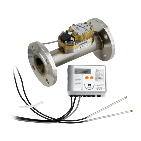
Beim statischen Wärmezähler Superstatic handelt es sich um ein Kom-
paktgerät. Es besteht aus den folgenden drei Teilgeräten:
- Statischer Durchflusssensor Superstatic 440
- Rechenwerk Supercal 531
- Temperaturfühler (2- oder 4-Leitertechnik) mit oder ohne Tauch-
hülsen
Die Impulswertigkeit des Rechenwerks und des Durchflusssensors
sowie der Widerstand der Temperaturfühler und Rechenwerk müssen
aufeinander abgestimmt sein.
Inst 440 531-d-e-190207 MID
Einbau- und Betriebsanleitung statischer Wärmezähler Superstatic 440
Installation and manual of static heat meter Superstatic 440
Bedingungen
betrieben
werden!
General
The static flow sensor and the integrator may only be operated within the
conditions outlined on the identification plate, as well as within the tech-
Bei
nical specification! In case of ignoring these default conditions, the
manufacturer's responsibility is void.
The manufacturer is not liable for inappropriate installation and opera-
tion. Seals may not be removed and/or only by authorized persons. The
country-specific, local regulations, as well as the manufacturer instruc-
tions must be observed!
If the manufacturer's seal has been broken or damaged, the manufac-
turer cannot be made responsible for the change of the verified and
measuring relevant data.
When using several heat meters in an installation unit, one should se-
lect, and in the interest of a at most possible fair heat consumption
measurement, the same types of device and installation positions.
Before installation
- Check the design layout data of the installation.
- The pulse value and the installation location of the flow sensor must
match the values indicated on the integrator, consult the identification
plate!
- The permissible ambient temperature range in the case of the
tegrator is 5 - 55 ºC.
- The installation and project prescriptions must be observed.
- The readability of the integrator and also the identification
plates must be observed.
Refers to for the meter installation
- The integrator is parameterized, as a standard, for an installation into
the return flow. Special parameterization is necessary for installation
in the supply and this must be specified with the order.
- The cable between the flow sensor and the integrator may not be
extended.
- All wiring must be installed with a minimum distance of 300 mm from
heavy voltage and high frequency cables.
- Radiated heat and interfering electrical fields close to the integrator
must be avoided.
- In general, the integrator should be installed away from the cooling
pipes.
- It has to be ensured that no condensate water can run along the
wiring into the calculator.
- If the danger of vibrations in the piping system exists, the integrator
should be installed separately on the wall.
- With temperatures over 90 °C the integrator must be installed a
part from the flow unit.
- The flow sensor should be installed between two shut-off valves.
- By the installation of the flow sensor it is to be made certain that the
measuring head is lying laterally or downward.
- For the flow sensors, please observe the flow direction (arrow on the
flow sensor).
- It is recommended to flush the pipe before installing the flow sensors.
This procedure guarantees that no foreign particles remain in the
pipe.
- In general and prior to the set-up the pipe should be free of air.
- Use only new and appropriate sealing material.
- Water tightness of the different connection should be verified.
- A lightning protection cannot be ensured; this protection has to be
made through the house installation.
The static heat meter Superstatic is a compact unit and consists of the
following three partial units:
-
Static flow sensor unit Superstatic 440
-
Integrator Supercal 531
-
Temperature sensors (2- or 4-wire) with or without pockets
The pulse values of the integrator and of the flow unit, as well as the
resistance value of the temperature sensors and the integrator are
matched one to the other.
Seite / page - 1
in-
Sontex SA, CH-2605 Sonceboz
Advertisement

Subscribe to Our Youtube Channel
Related Manuals for Sontex Superstatic 440


Summary of Contents for Sontex Superstatic 440
- Page 1 Einbau- und Betriebsanleitung statischer Wärmezähler Superstatic 440 Installation and manual of static heat meter Superstatic 440 Allgemeines General Der statische Durchflusssensor und das Rechenwerk dürfen nur The static flow sensor and the integrator may only be operated within the innerhalb der auf dem Typenschild sowie in der technischen...
- Page 2 Einbau- und Betriebsanleitung statischer Wärmezähler Superstatic 440 Installation and manual of static heat meter Superstatic 440 Kabelanschlüsse Cable connection Zum Anschluss der Ein- und Ausgänge ist das Oberteil des Rechenwerks To connect the inputs and outputs the integrator’s upper part must be zu entfernen.
- Page 3 Einbau- und Betriebsanleitung statischer Wärmezähler Superstatic 440 Installation and manual of static heat meter Superstatic 440 spannungsführende Teile freigelegt werden. Weiterhin können Anschluss- implemented by a trained and an authorized specialist. If the housings stellen spannungsführend sein. Sämtliche Reparaturen- und Wartungs- and/or the connecting cable show any damage, the integrator unit arbeiten dürfen nur von einer hierfür ausgebildeten und befugten Fachkraft...
- Page 4 Einbau- und Betriebsanleitung statischer Wärmezähler Superstatic 440 Installation and manual of static heat meter Superstatic 440 Temperaturfühlereinbau bei Kälteanlagen Temperature sensor installation by cooling application Die Isolation darf nur bis zur Temperaturfühlerver- The isolation may be made only up to the temperature schraubung vorgenommen werden.
- Page 5 Einbau- und Betriebsanleitung statischer Wärmezähler Superstatic 440 Installation and manual of static heat meter Superstatic 440 Einhaltung der Betriebsbedingungen gemäss MID Adherence to the operating conditions in accordance with MID • • Die Temperaturfühler sind symmetrisch in den Vor- und Rücklauf The temperature sensors are to be built symmetrically into advance und vorzugsweise direkt einzubauen.
- Page 6 Einbau- und Betriebsanleitung statischer Wärmezähler Superstatic 440 Installation and manual of static heat meter Superstatic 440 Beispiel der Menüführung Example of the menu guidance Monatswerte Stichtage Hauptmenü Monthly values Set days Main menu Zurück zur Zurück zur Zurück zur Hauptebene...
- Page 7 Einbau- und Betriebsanleitung statischer Wärmezähler Superstatic 440 Installation and manual of static heat meter Superstatic 440 Haupmenü Stichtagsmenü Monatswerte Main menu Set day menu Monthly values 000432i.0 0i.07.2005 0i.0i.2006 0i.--.---- 1 2 3 4 5 6 7 1 2 3 4 5 6 7...
- Page 8 Einbau- und Betriebsanleitung statischer Wärmezähler Superstatic 440 Installation and manual of static heat meter Superstatic 440 Mittelwerte Maximalwerte Average values Maximum values 03-32 03-32 0 0 0 5 3 . 5 2 5 0 0 0 4 8 . 2 2 5 0 0 0 5 3 .
- Page 9 Einbau- und Betriebsanleitung statischer Wärmezähler Superstatic 440 Installation and manual of static heat meter Superstatic 440 Konfiguration Service Prüfprogramm Configuration Service Test mode i 7 . 0 3 . 2 0 0 6 6 0 5 2 5 6 2 3...
- Page 10 Einbau- und Betriebsanleitung statischer Wärmezähler Superstatic 440 Installation and manual of static heat meter Superstatic 440 Achtung Attention Empfohlene Einbaulage Kritische Einbaulage Wenn sich die Messelektronik seitlich oder nach unten Lufteinflüsse könnten befindet, ist automatisch gewährleistet dass allfällige Messergebnisse beeinflussen, Lufteinflüsse beseitigt werden!
- Page 11 Einbau- und Betriebsanleitung statischer Wärmezähler Superstatic 440 Installation and manual of static heat meter Superstatic 440 Massbilder statisches Durchflusssensor Superstatic 440 Diemension static flow sensor Superstatic 440 Fig.No B (mm) H (mm) L(mm) ¾” 16 / 25 1” 16 / 25 1.5 m...
- Page 12 WE RESERVE THE RIGHT TO MAKE TECHNICAL MODIFICATIONS Die detaillierte Konformitätserklärung zum Herunterladen finden Sie auf unserer Homepage www.sontex.ch/enterprise-d.html Konformitätserklärung The detailed declaration of conformity can be found and downloaded on our homepage www.sontex.ch/enterprise-d.html Declaration of confirmity Inst 440 531-d-e-190207 MID...
Need help?
Do you have a question about the Superstatic 440 and is the answer not in the manual?
Questions and answers