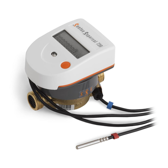
Sontex Supercal 739 Instruction Manual
Thermal energy meter
Hide thumbs
Also See for Supercal 739:
- Instructions for use manual (30 pages) ,
- User manual (13 pages) ,
- Installation manual (8 pages)
Table of Contents
Advertisement
Quick Links
Installation guide Thermal Energy Meter Supercal 739
Installation
The prescriptions related in the standard EN1434-6 must be respected when the Supercal 739 is installed.
Depending on its particular version and use (heat and/or cooling meter), the energy meter must be fitted on the "cold" or "hot" pipe side of the
installation in compliance with the indications showed on the LCD display, 1
In the standard version, the integrator is parameterised by default for installation on the "cold" pipe side. Installation on the "hot" pipe side must be specified
with the order.
In any particular installation, mixed mounting positions (horizontal and vertical) must be avoided because the measuring ranges are different.
Place the flow meter correctly according to the direction of the fluid (an arrow can be seen on the flow meter).
Horizontal mounting with the integrator facing downwards is not permitted. Also avoid fitting in a position which may cause an air bubble to build up inside
the mechanical meter.
The energy meter must be fitted between two shutoff valves. The flow meter must be installed ahead of any monitoring valves so as to avoid any potentially
interfering influence. Waterproof will be checked at the various mounting points.
The heat conveying liquid must be equivalent to water without any additives according to standard FW510 of the AGFW (German District Heat-
ing Association). If additives are added to the water, the user must ensure the compatibility of the materials used in the thermal energy meter which are in
contact with these additives.
The integrator can be separated from the flow meter and installed at a sufficient distance from the flow meter if:
-
The meter has to be installed in a confined space.
-
In a cooling installation, possibility to isolate the flow meter.
The pipes are generally free from air before the installation is brought into service. Follow the insulation instructions for cooling installations. Final commis-
sioning must be performed and documented.
Wall-mounting of the integrator
The integrator can be separated from the flow meter and fixed against a wall using the wall fixture supplied with the energy meter. If possible, install the
wall fixing component above the flow meter.
The wall fixing component, together with a double-sided adhesive tab, is delivered with the Supercal 739 (Figure 1).
The wall fixing component can also be screwed on to the wall (screws are not supplied).
To separate the integrator from the flow meter press laterally with one hand on the two locking buttons, while pulling the integrator upwards (Figure 2).
Fix the integrator onto the wall fixing component taking care not to jam the cable which connects the integrator to the flow meter and stick the adhesive tab
behind the wall component. Secure the assembly to the wall (Figure 3).
Figure 1
To remove the integrator from the wall support, it will be sufficient to press laterally on the two locking buttons while pulling the assembly towards you.
Rewind the connection cable at the position provided for this purpose on the flow meter (1) and re-insert the integrator (2).
0739P300-E Installation Supercal 739 EN 17-03-2016
st
position of the service menu "hot pipe" / "cold pipe".
Figure 2
(2)
1
Figure 3
(1)
Sontex SA, 2605 Sonceboz, Switzerland
Advertisement
Table of Contents

Related Manuals for Sontex Supercal 739


Summary of Contents for Sontex Supercal 739
- Page 1 The wall fixing component, together with a double-sided adhesive tab, is delivered with the Supercal 739 (Figure 1). The wall fixing component can also be screwed on to the wall (screws are not supplied).
- Page 2 -Blue for mounting in the pipe on the “cold” side. The Supercal 739 is delivered with a cable length of 1.5 m for the temperature sensors. The temperature sensors form a sub-assembly matching the integrator. The temperature sensor cables must be neither shortened nor lengthened.
- Page 3 Tighten by hand the M12x1.5 mm female nut until stumbled on the pocket. Check the watertightness of the temperature sensor placed under pressure. Seal the temperature sensor. 0739P300-E Installation Supercal 739 EN 17-03-2016 Sontex SA, 2605 Sonceboz, Switzerland...
- Page 4 The location of the temperature sensor bump against the nut from the EAS The original nut of the EAS base must be replace by the nut with thinner head 0714P089. EAS base with integrated ball valve 0739P300-E Installation Supercal 739 EN 17-03-2016 Sontex SA, 2605 Sonceboz, Switzerland...
- Page 5 Commissioning and checking operation After installing the Supercal 739 compact energy meter, the temperature sensors and the flow meter must be sealed and brought into service. The waterproof of the installation must be checked. Make sure that the measurements indicated by the meter are coherent using the orange button which you will find on the meter. The following values can be shown on the LCD display: flow, power, hot and cold temperatures.
- Page 6 The compact mechanical single or multiple jet thermal energy meter Supercal 739 is a precision measuring instrument approved for individual metering of heating systems and must be handled with care. The Supercal 739 is available in a heating or cooling version and determines the thermal or cold energy exchanged by a heat-bearing fluid in a heat ex- changer circuit.
- Page 7 Error codes The Supercal 739 integrator displays an error message with the 3 letters “Err” and a code. If several errors occur at the same time, the different codes are added together. The error is displayed in the first position of the display menu. It will still be possible to select all the other display menus by pressing the navigation button.
- Page 8 1.04 SW version Kurzes Drücken / Pression courte / Short pression on button Segmenttest Test des segments Test LCD Langes Drücken / Pression longue / Long pression on button 0739P300-E Installation Supercal 739 EN 17-03-2016 Sontex SA, 2605 Sonceboz, Switzerland...
- Page 9 The M-Bus protocol is compliant with standard EN1434-3. By default, the primary address will be configured with the address 0 and the secondary address will correspond to the serial number of the Supercal 739. To change the value of the secondary address, you must use Prog739-749 software or send M-Bus specific orders. The secondary address corresponds to the identification field ID.
- Page 10 Seal installed in the factory (2) on the integrator For the Supercal 739 with coaxial multiple jet meter, the detector support (3) fitted to the flow sensor (4) can’t be removed A factory seal (1) will be applied to the temperature sensor, mounted in the capsule with the threaded union G2’’.
- Page 11 1" (20) Brass 0.19 1" (20) Brass 0.23 *EAS: base Length of straight section fitted upstream/downstream of each flow meter (EN1434): U0 / D0 16 bar = 1.6 MPa 0739P300-E Installation Supercal 739 EN 17-03-2016 Sontex SA, 2605 Sonceboz, Switzerland...
- Page 12 Type Examination Certificate CH-MI004-13018 Technical support For technical support, please contact your local Sontex agent or Sontex SA directly. Sontex Hotline:sontex@sontex.ch, +41 32 488 30 04 Declaration of conformity for devices compliant with the MID directive The detailed certificate of conformity can be consulted on the Sontex website: www.sontex.ch...
Need help?
Do you have a question about the Supercal 739 and is the answer not in the manual?
Questions and answers