Table of Contents
Advertisement
Quick Links
Advertisement
Table of Contents
Troubleshooting

Related Manuals for Sontex Supercal 5 I


Summary of Contents for Sontex Supercal 5 I
- Page 1 Supercal 5 I Instructions for Use...
- Page 2 The information contained in this document is the property of Sontex SA. Publication, in whole or in part, requires the written consent of Sontex SA. Any internal reproduction in- tended for evaluation of the product or its proper use is permitted and not subject to au- thorisation.
-
Page 3: Table Of Contents
Table of Contents Notes on this Document Scope of Validity Target Groups Storage of Document Further Information Symbole Safety Personnel Qualification Intended Use Safety Instructions 2.3.1 Occupational Safety 2.3.2 Operational safety 2.3.3 Product Safety Description Identification 3.1.1 Front Panel 3.1.1 Scope of Delivery Certificates and Approvals 3.3.1... - Page 4 5.5.1.1 Technical Characteristics of the Pulse Input for Volume Counting 5.5.2 Two Additional Pulse Inputs Connecting Outputs 5.6.1 Two Open-Collector Pulse Outputs 5.6.1.1 Technical Characteristics of the Two Open-Collector Pulse Outputs M-Bus Communication 5.7.1 Timing M-Bus Communication 5.7.1.1 Technical Characteristics of embedded M-Bus Radio Modules 5.8.1 Radio Telegram...
- Page 5 Technical Information 11.1 Calculator Supercal 5 I 11.2 Power Supplies 11.2.1 Mains Modules 11.2.2 Battery Modules 11.2.3 Estimating the Battery Life of an M-Bus Application 11.3 Measurement concept 11.4 Arithmetic Logic Unit 11.5 Flow Sensors 11.6 Flow Measurement 11.7 Flow Calculation 11.7.1...
- Page 6 Instruction for use | Supercal 5...
-
Page 7: Notes On This Document
The system operator must ensure that this document is accessible to the responsible personnel at all times. If the original document is lost, an up-to-date version can be down- loaded from our extranet (https://extranet.sontex.ch/index/). 1.4 Further Information Links to further information can be found at www.sontex.ch. Instruction for use | Supercal 5... -
Page 8: Symbole
1.5 Symbols Symbol Significance DANGER! DANGER Failure to observe these warnings leads to fatal or serious injury. WARNING! WARNING Failure to observe these warnings may lead to fatal or serious injury. CAUTION! CAUTION Failure to observe these warnings may lead to moderate injury. NOTICE! NOTICE Failure to observe these warnings may result in damage to property. -
Page 9: Safety
Further information and data can be found in the product’s catalogues and data sheets, through your local representative, or on the Sontex homepage at www.sontex.ch. All technical data are without guarantee. -
Page 10: Operational Safety
It meets the general safety and legal requirements. It also conforms to the EC directives listed in the device-specific EC Declaration of Conformity. Sontex SA confirms this by affix- ing the CE mark. -
Page 11: Description
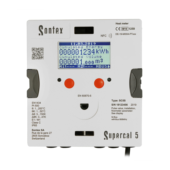
See Display M-Bus Interface EN 13757-2 Standard optical interface EN 60870-5 Optional Radio Interfaces Sontex radio 433 MHz wM-Bus 868 MHz No Radio NFC Chip Location NFC ))) Sontex Address Rue de la Gare 27, 2605 Sonceboz. Switzerland * In case of Supercal 5 S is acquired, it is identified as 5 S. - Page 12 EN 6070-5 Type: SC5I EN1434 S/N: 26277017 2021 Pt 500 E1 / M1 Pulse value, installation, IP65 flowmeter parameters: See display M-Bus wM-Bus 868MHz Sontex SA Rue de la Gare 27 2605 Sonceboz Calculator Switzerland Instruction for use | Supercal 5...
-
Page 13: Scope Of Delivery
3.2 Scope of Delivery The scope of delivery of the Supercal 5 includes: Installation guide Stickers (seals) Optional modules 3.3 Certificates and Approvals The Supercal 5 and the optional pair of temperature sensors meet the requirements of Di- rective 2004/22/EC (L 135/1) (until 19.4.2016) or 2014/32/EU (L 96/149) (from 20.4.2016) (Measurement Instruments Directive, MID), as well as OIML R75 and EN-1434. -
Page 14: Installation
4.3 Checking the Scope of Delivery Check the scope of delivery for completeness and possible damage. Contact your dealer or Sontex SA in case of faulty delivery. 4.4 Structure and Components of the Calculator The Supercal 5 calculator consists of: A cover section, containing measuremant and calibration components ... -
Page 15: Calculator Cover
4.4.1 Calculator Cover 4.4.2 Calculator Body The following elements are located in cover and body part of the calculator: Sontex or customer logo Rubber gommets (IP65) Dot-Matrix Display Strain reliefs for connection cable and earthing Brackets for Housing opening/closing Two slots for optional communication modules... -
Page 16: Dimensions
4.5 Dimensions 159.6 53.5 163.6 175.1 4.6 Mounting 4.6.1 Before Mounting All cables must be laid at least 300 mm away from power and high- frequency cables. Radiant heat and electrical interference fields in the vicinity of the calculator must be avoided. -
Page 17: Wall Mounting
Check the design data of the components. The flow sensor’s pulse factor and location must correspond to the datasheet values; check the type plates! The permissible ambient temperature for the calculator is 5 ... 55 °C. The installation and project planning regulations must be adhered to. ... -
Page 18: Top Hat Rail Mounting
tion 4.6.3 Top Hat Rail Mounting é 4.7 Installation Instructions for Temperature Sensors Great care must be taken in selecting and installing temperature sensors. Errors made here cannot be compensated even by the best calculator. CAUTION Take care when installing the temperature sensors! Incorrect removal of directly immersed temperature sensors may result in an acci- dent! Installation and removal may only be carried out by authorized and competent personnel. -
Page 19: Installation Of Temperature Sensors
In pipelines up to DN 150, temperature sensors may be installed directly or using pockets. The sensor tip should be located as close as possible to the middle of the pipeline. Extensive information on the subject of temperature sensors can be found in our Sontex temperature sensor overview at: www.sontex.ch/downloads/ under the heading tempera- ture sensor 460. -
Page 20: Connection Of 4-Wire Temperature Sensors
50 m. The connection cable must have four wires with a cross-section of at least 0,5 mm The insulation of the temperature sensor cables can be PVC or silicone. Sontex recommends the use of silicone insulation. 1/5 and 2/6... -
Page 21: Installation Guidelines For Temperature Sensors According To En1434
4.7.3 Installation Guidelines for Temperature Sensors According to EN1434 4.7.3.1 Compliance With the Operating Conditions According to MID for the Temperature Sensors The temperature sensors must be installed symmetrically in the flow and return pipes pref- erably directly. If temperature sensors are installed with pockets, both must be tested for conformity. -
Page 22: Supercal 5S Installation Considerations (Including Flowmeter)
4.9 Supercal 5S Installation Considerations (including flowmeter) Before installation Check the layout and design data of the installation. The calculator’s pulse factor and the installation location settings must match the values indicated on the flow sensor - consult the identification plate! The permissible temperature operating range of the calculator is 5–55 ºC. -
Page 23: Wiring
5. Wiring 5.1 Wiring Requirements DANGER Danger due to electrical voltage! The entire electrical system must be voltage-free. CAUTION Additional Electrical Information Before commissioning, ensure the supply voltage conforms to the information in the nameplate. Provide a suitable switch or circuit breaker in the building installation. This switch must be installed easily ... -
Page 24: Power Supply At The Calculator
5.4 Power Supply at the Calculator Supercal 5 can be supplied with either battery or external mains modules. These can be retrofitted at any time. 5.4.1 Power Supply Modules The mains module is equipped with a backup battery already installed. 5.5 Connecting Sensors 5.5.1 Pulse Input for Volume Counting The Supercal 5 allows the connection of slow and fast flow sensors. -
Page 25: Two Additional Pulse Inputs
Electrical pulse diagram 1 / f Inactive Active Designation Description Normal mode: t1 = t2 min. 100 ms (with duty cycle = 50 %) Fast mode (mains operation): t1 = t2 min. 2,5 ms (with duty cycle = 50 %) Vin max. -
Page 26: Technical Characteristics Of The Two Open-Collector Pulse Outputs
5.6.1.1 Technical Characteristics of the Two Open-Collector Pulse Outputs Description Value designation 2 outputs OUT1 at terminal 16/17 OUT2 at terminal 18/19 Normal mode Voltage max. 30 VDC Current max. 100 mA Voltage drop approx. 1,3 V at 20 mA Duty cycle 1 : 1 Electrical pulse duration... -
Page 27: M-Bus Communication
5.7 M-Bus Communication M-Bus is embedded in the new Supercal 5 hardware. Up to two further communication mod- ules can be added in the available slots. This ensures that up to three M-Bus requests for different applications can be processed and answered simultaneously. The two additional electrical pulse inputs are automatically integrated into the M-Bus telegram and transmit- ted. -
Page 28: Radio Modules
5.8 Radio Modules Ex-factory the Supercal 5 can be configured with the following variants: Sontex Radio wM-Bus Radio No radio Sontex Radio Description Proceedings Bi-directional Frequency 433.82 MHZ Transmitting power ≤ 10 mW Range Average 30 m, depending on the spatial and structural conditions... -
Page 29: Operation
6. Operation NOTICE The safety and service marks relevant to calibration must not be damaged or removed. Otherwise the warranty of the device is void. User seals may only be removed by authorized persons for service purposes and must then be renewed. Once the optional module has been installed, the Supercal 5 calculator must be ... -
Page 30: Menus
6.4 Menus Six menus are available. The Overview menu is used to select the operational menus: Main, Metrological, Configuration, Service and Commissioning. The Commisioning menu is only available when the calculator is used for the first time, or when the calculator is manually “unsealed”. Notes The error message in the main menu only appears if an error is present. -
Page 31: Main Menu
6.6 Main Menu Errors Cumulated Energy / Cumulated volume Cumulated Energy Tarif 1 / Cumulated volume tarif 1 Cumulated Energy Main Menu Tarif 2 / Cumulated volume tarif 2* Cumulated value Metrological Cumulated value Cumulated value Configuration Cumulated value IN4 ** Cumulated value Service Cumulated value IN6 ** Temperatures High- ... - Page 32 ERROR: error menu 2655: sum of the error codes Error Description: Sensor 1 Missing Error Description: Sensor 2 Missing Paging through the Main Menu displays shows the calculator’s most important data as shown below: 1 × ...
- Page 33 Active only when input module is in slot 2. This menu must be activated with Super- prog Windows. 1 × Cumulated Input value 5 Cumulated Input value 6 1 × Temperature high Temperature low ...
-
Page 34: Overview Menu
6.7 Overview Menu From any Menu, a two second press on the right button and the left button opens the Overview Menu and shows all available menus, as shown below. ◄: a short press moves the selection up ► a short press moves the selection down ... - Page 35 The Metrological menu alllows customers to set up and view metrological data, as shown below. 1 × Mounting position Electrical Pulse value Active only for Supercal 5 S 1 × Accuracy class DN: nominal diameter ...
- Page 36 Active only for Supercal 5 S 1 × Fluid type Concentration 1 × Cumulated energy tariff 0 with five more significant digits 1 × Cumulated volume tariff 0 with five more significant digits A long press on the right button has no function in Metrological Setup.
-
Page 37: Stored Data
6.9 Stored Data All the following data is stored in the internal memory of the Supercal 5 and it can be read from the Superprog Windows software: Totalizer values in a period of time Average values in a period of time ... - Page 38 The Configuration menu allows customers to set and display the configured data, as shown below: Address Baud rate Identification number 1 × Current date Current time 1 × Electrical pulse Unit IN1 ...
- Page 39 Active only when input module is in slot 2. This menu must be activated with Super- prog Windows. 1 × Electrical pulse Unit IN5 Electrical pulse value IN5 Active only when digital input module is in slot 2.
-
Page 40: Service
Active only when digital ouput module is in slot 2. This menu must be activated with Superprog Windows. 1 × Pulse unit OUT5 Multiplier OUT5 for number of pulses Active only when digital output module is in slot 2. - Page 41 Service is customer’s menu that contains informative data, as shown below. 1 × Serial number 1 × Firmware version Firmware CRC32 * Firmware version and CRC32 may be dif- ferent for future firmware versions. 1 ×...
-
Page 42: Sealing
Connecting the flowmeter to the Supercal 5 I Then the Supercal 5 I must be sealed by using the menu on the display according to chapter 7. The installer can modify any other metrological parameter with Superprog Android and Superprog Windows at any time. - Page 43 Historical events can be customized as follows: Maximum number of records Which event The historical values can be downloaded from the Supercal 5 by M-Bus. Average value Event Totalizer history Peak value history history history Period Monthly Biannually Biannually Biannually Monthly...
-
Page 44: Commissioning
7. Commissioning Make sure that all final checks have been performed before putting your device into oper- ation. 7.1 Commissioning of the Supercal 5 The new Supercal 5 has a backup battery with 10 years life-time, and doesn’t require any other type. -
Page 45: Reaction Time And Accuracy Of The Flow Calculation
Both software can be downloaded from the Sontex Extranet at https://extranet.sontex.ch/index/ Only authorized users have access to the extranet. Information and access rights to the Sontex Extranet can be obtained from your local Sontex representative. 7.3.1.1 Solar and Refrigeration Systems The Supercal 5, while initially calibrated for water, provides precise measurement even with glycol mixtures. -
Page 46: Power Supply
9.1 General Troubleshooting Procedure. 9.1 General Troubleshooting Procedure See Chapter 9.3.1. If this doesn’t lead to success, please contact your Sontex representative. The contact de- tails can be found on the Internet at www.sontex.ch/contact/. 9.2 Fault Indication All error messages are automatically cleared on the LCD display 60 seconds after troubleshooting. -
Page 47: Error Messages
9.3 Error Messages If several errors are present at the same time, the individual error mes- sages are added together and displayed. If an error occurs for more than one hour, it is stored in the error memory with date and time (start of error) and duration (in minutes). -
Page 48: Troubleshooting M-Bus
As an ISO-certified company, Sontex is required by law to handle all returned products in a specific manner. To ensure a safe, professional and fast return of your device, please refer to the Sontex web- site for procedures and conditions and use our Return of Goods Form as described in Chapter 14. -
Page 49: Technical Information
11. Technical Information 11.1 Calculator Supercal 5 Technical Data Temperature Measurement Pt500 according to EN 60751 2- or 4-wire Absolute temperature range −20 °C to 200 °C Approved range 1 °C to 200 °C Homologation range ... -
Page 50: Power Supplies
11.2 Power Supplies The Supercal 5 is always supplied with a battery and can also be supplied with mains power supply module. These can be modified and retrofitted at any time. 11.2.1 Mains Modules 12- 24 VDC or 12- 36 VAC Article number: SC5X00011 Type safety extra-low voltage Voltage tolerance... -
Page 51: Arithmetic Logic Unit
Its flow rate is determined with a suitable flow sensor. A pair of temperature sensors determine the “warm pipe temperature” and the “cold pipe temperature” of the heat transfer medium. When ΔT > 0,2 K, the energy con- sumed is calculated. -
Page 52: Flow Calculation
11.7 Flow Calculation Flow calculation is based on the time elapsed between impulses from the flow sensor. For the first flow calculation, the calculator requires two volume pulses for the calculation of the effective flow. Depending on the configuration, the internal flow rate calculation and the immediate display of the current flow rate on the LCD display take place. -
Page 53: Permissible Errors And Limit Values
“temperature sensor high” in the return flow. The Supercal 5 I are generally tested ex works in accordance with the metrological measur- ing points of EN1434 (2006) for refrigeration and heat energy. -
Page 54: Insulation Regulations For Refrigeration Systems
11.9.4 Insulation Regulations for Refrigeration Systems In refrigeration systems, the mechanical flow sensors and the temperature sensors may only be insulated up to the screw connection. condensation water condensation water (capillary effect possible 11.10 Calibration and Measurement Data If calculators are used for the direct billing of energy between energy supplier and consumer (public payment transactions), they are subject to calibration in most EU countries. - Page 55 The interfaces of the NOWA adapter Instruction for use | Supercal 5...
-
Page 56: Notes On Project Planning
The Supercal 5 calculator is produced in accordance with the state of the art and complies with EN1434 and is reliable in operation. If the calculator is operated outside the specifica- tions defined here or is not handled in accordance with the regulations, all Sontex service and warranty services will be void. -
Page 57: Refrigeration Plants
12.9 Service and Repairs Service and repair work may only be carried out by qualified personnel who have been ex- pressly authorized by Sontex. 12.10 Installation Information The calculator must generally be mounted separately from the heat or ... -
Page 58: Appendix
13.1.1 The “Cut Off” Function of the Superstatic 440 The combination of the Supercal 5 I with the Superstatic 440 static flow sensor defines and limits the possible flow measuring range ex works with a lower and an upper threshold val- ue (“cut off”... - Page 59 Table of factory-set threshold values according to PTB Metrological Class C. “Length “Qn “Qt “Qmin “Qa (50 °C) “Cut off “Flow satura- Connection (mm)” /h)” /h)” /h)” /h)” /h)” tion (m /h)” G 3/4’’ 0,060 0,010 0,004 0,003 2,400 G 3/4’’ 0,090 0,015 0,010...
-
Page 60: Pressure Loss Curve
13.2 Pressure Loss Curve 13.3 Dimension fluidic oscillator flow sensor Superstatic 440 # bolts Fig.No B (mm) H (mm) L(mm) (Ø mm) – ¾” 16 / 25 – 1” 16 / 25 1,5 m – ¾” 16 / 25 1,5 m –... - Page 61 299,98 h (Ø mm) L (mm) D (mm) H (mm) # bolts (M) 15 m 16, 25 Ø 125 4 (M 16) 25 m 16, 25 Ø 145 8 (M 16) 40 m 16, 25 Ø 160 8 (M 16) 40 m 16, 25 Ø...
-
Page 62: Technical Data Flow Sensor Superststic 440
13.4 Technical Data flow sensor Superstatic 440 Threaded Flanged Length Mat. Maximal Minimal Low flow thres- Threaded Weight Kvs value Pressure connection connection flow qs flow qi hold value hole for (*) (**) (at 20°C) loss at (50°C) sensor G" (EN ISO (ISO 7005-3) 228-1) -
Page 63: Optional Communication Modules Overview
Software for reading and writing parameters in Supercal 5 Superprog Windows The link to download the software can be found on our Extranet My Sontex. Access is password protected. Please contact your local representative for more information. Commissioning Software for Supercal 5... -
Page 64: Return Of Good Form
Warranty conditions: Please refer to our General Terms and Conditions Shipment address: Sontex SA Rue de la Gare 27 2605 Sonceboz Switzerland Sontex SA 2605 Sonceboz Switzerland Tel +41 32 488 30 00 Email sontex@sontex.ch www.sontex.ch Instruction for use | Supercal 5... -
Page 65: Country List
MID 2014/32/EU and RED 2014/53EU. The full text of the EU Declaration of Conformity is available at the following Internet link: Technical support For technical support contact your local Sontex agent or Sontex SA directly. Hotline Sontex: support@sontex.ch +41 32 488 30 04... - Page 68 Sontex SA Rue de la Gare 27 Tel. +41 32 488 30 00 CH-2605 Sonceboz sontex@sontex.ch www.sontex.ch...
Need help?
Do you have a question about the Supercal 5 I and is the answer not in the manual?
Questions and answers