Table of Contents
Advertisement
Quick Links
www.ti.com
User's Guide
INA226EVM User's Guide
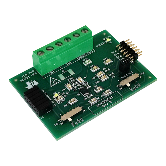
This user's guide describes the characteristics, operation, and use of the INA226 evaluation module (EVM).
This EVM is designed to evaluate the performance of the INA226. Throughout this document, the terms
evaluation board, evaluation module, and EVM are synonymous with the INA226EVM. This document includes a
schematic, reference printed circuit board (PCB) layouts, and a complete bill of materials (BOM).
SBOU276 – JANUARY 2023
Submit Document Feedback
ABSTRACT
Copyright © 2023 Texas Instruments Incorporated
INA226EVM User's Guide
1
Advertisement
Table of Contents

Subscribe to Our Youtube Channel
Related Manuals for Texas Instruments INA226


Summary of Contents for Texas Instruments INA226
- Page 1 This user’s guide describes the characteristics, operation, and use of the INA226 evaluation module (EVM). This EVM is designed to evaluate the performance of the INA226. Throughout this document, the terms evaluation board, evaluation module, and EVM are synonymous with the INA226EVM. This document includes a schematic, reference printed circuit board (PCB) layouts, and a complete bill of materials (BOM).
-
Page 2: Table Of Contents
Table of Contents www.ti.com Table of Contents Trademarks....................................2 Overview....................................3 2.1 Kit Contents..................................3 2.2 Related Documentation From Texas Instruments......................3 Hardware....................................3.1 Features..................................... Operation....................................4 4.1 Quick Start Setup................................4.2 EVM Operation...................................4 5 Circuitry....................................5.1 Current Sensing IC................................19 5.2 Input Signal Path................................19 5.3 Digital Circuitry................................. -
Page 3: Overview
The INA226 senses current on common-mode bus voltages that can vary from 0 V to 36 V, independent of the supply voltage. The device operates from a single 2.7-V to 5.5-V supply, drawing a typical of 330 µA of supply current. -
Page 4: Features
If using multiple EVMs, connect them as shown in Figure 4-2. Make sure to use a different I2C address for each device. The GUI only supports up to 4 EVMs total. INA226EVM User’s Guide SBOU276 – JANUARY 2023 Submit Document Feedback Copyright © 2023 Texas Instruments Incorporated... - Page 5 While shorting the two test points labeled DFU (shown in Figure 4-3) with a pair of tweezers (or wire), press and release the RESET button. SBOU276 – JANUARY 2023 INA226EVM User’s Guide Submit Document Feedback Copyright © 2023 Texas Instruments Incorporated...
- Page 6 GUI link. 3. Open the GUI Composer application to launch the GUI from the web browser (see Figure 4-4). Figure 4-4. GUI Composer Application INA226EVM User’s Guide SBOU276 – JANUARY 2023 Submit Document Feedback Copyright © 2023 Texas Instruments Incorporated...
- Page 7 Many connectivity issues can be addressed by doing one of the following: 1. Long-press the RESET button on the EVM with the EVM and SCB connected to each other. SBOU276 – JANUARY 2023 INA226EVM User’s Guide Submit Document Feedback Copyright © 2023 Texas Instruments Incorporated...
- Page 8 GUI to EVM Connection), as well as access helpful resources through the buttons on the bottom (see Figure 4-9). Figure 4-9. Home Tab Links INA226EVM User’s Guide SBOU276 – JANUARY 2023 Submit Document Feedback Copyright © 2023 Texas Instruments Incorporated...
- Page 9 – Input the value of the used shunt resister in mΩ. • Max Expected Current – Input the value of the maximum expected current across the shunt resistor in Amps. SBOU276 – JANUARY 2023 INA226EVM User’s Guide Submit Document Feedback Copyright © 2023 Texas Instruments Incorporated...
- Page 10 4-11. Figure 4-11. GUI Registers Tab From this page, you can read and write device registers on the EVM. Here are some important notes: INA226EVM User’s Guide SBOU276 – JANUARY 2023 Submit Document Feedback Copyright © 2023 Texas Instruments Incorporated...
- Page 11 Figure 4-12. Save and Load Register Settings – TI recommends to press the Read All Registers button after loading data to update the register map with the actual device values. SBOU276 – JANUARY 2023 INA226EVM User’s Guide Submit Document Feedback Copyright © 2023 Texas Instruments Incorporated...
- Page 12 – Changing the switch settings of any EVM sets that EVM as the selected EVM. • Collect/Plots settings INA226EVM User’s Guide SBOU276 – JANUARY 2023 Submit Document Feedback Copyright © 2023 Texas Instruments Incorporated...
- Page 13 – If this field is empty when Manual Scale is selected, then it will auto populate with the minimum value currently in the plot. SBOU276 – JANUARY 2023 INA226EVM User’s Guide Submit Document Feedback Copyright © 2023 Texas Instruments Incorporated...
- Page 14 EVM. Figure 4-15 shows a convenient way to use the multiple IN+ and IN- terminals with an external shunt for this use case. INA226EVM User’s Guide SBOU276 – JANUARY 2023 Submit Document Feedback Copyright © 2023 Texas Instruments Incorporated...
- Page 15 4. Connect the system ground to the GND terminal (J1 pin 1). 5. Power on the system, and observe the device states and outputs through the GUI. SBOU276 – JANUARY 2023 INA226EVM User’s Guide Submit Document Feedback Copyright © 2023 Texas Instruments Incorporated...
- Page 16 I2C EVM connected to use I2C. – For example, to set the INA226 with a register address of 0x4A you could send the command: setdevice – For this example, the EVM would return the acknowledgment and state ("idle" or "collecting") in JSON format: {"acknowledge":"setdevice 10"}...
- Page 17 Stop collecting data format: stop – Where stop is always lower case. – The EVM will return the acknowledgment and state in JSON format: {"acknowledge":"stop"} {"evm_state":"idle"} SBOU276 – JANUARY 2023 INA226EVM User’s Guide Submit Document Feedback Copyright © 2023 Texas Instruments Incorporated...
- Page 18 Note not to add too much resistance in the jumper wire connection setup or the signal may degrade and cause communication errors. Figure 4-16. EVM to PAMB Connection INA226EVM User’s Guide SBOU276 – JANUARY 2023 Submit Document Feedback Copyright © 2023 Texas Instruments Incorporated...
-
Page 19: Circuitry
This section describes the INA226 and supporting components. U1 is the INA226 current-sensing device. C1 and C2 are bypass capacitors that are placed near the sensor to help mitigate power supply noise and provide current quickly to the device when needed. LED D1 with current limiting resistor R4 are used to indicate when the EVM is powered on. -
Page 20: Schematics, Pcb Layout, And Bill Of Materials
INA226AIDGSR PD2_B 1µF 0.1uF CUS-14TB ALERT 4.7k +3V3 PD2_A PD2_B +3V3 +3V3 SH-J4 PD2_B PD2_A MNT_1 MNT_2 MNT_3 MNT_4 CUS-14TB Figure 6-1. Schematic Circuitry INA226EVM User’s Guide SBOU276 – JANUARY 2023 Submit Document Feedback Copyright © 2023 Texas Instruments Incorporated... - Page 21 These assemblies must comply with workmanship standards IPC-A-610 Class 2, unless otherwise speci e d. ¤ Assembly Note Trim the leads under J1 (back of PCB) to give clearance from surface Figure 6-2. Hardware Schematic SBOU276 – JANUARY 2023 INA226EVM User’s Guide Submit Document Feedback Copyright © 2023 Texas Instruments Incorporated...
-
Page 22: Pcb Layout
Figure 6-6 illustrate the PCB layers of the INA226EVM. Figure 6-3. Top View Figure 6-4. Top Layer Figure 6-6. Bottom Layer Figure 6-5. Bottom View INA226EVM User’s Guide SBOU276 – JANUARY 2023 Submit Document Feedback Copyright © 2023 Texas Instruments Incorporated... -
Page 23: Bill Of Materials
0.200 inch 10 mOhms ±0.5% 2W Chip Resistor 2512 (6432 Metric) Automotive AEC- 2512 PCS2512DR0100ET Ohmite Ω Q200, Current Sense, Moisture Resistant Metal Film SBOU276 – JANUARY 2023 INA226EVM User’s Guide Submit Document Feedback Copyright © 2023 Texas Instruments Incorporated... - Page 24 STANDARD TERMS FOR EVALUATION MODULES Delivery: TI delivers TI evaluation boards, kits, or modules, including any accompanying demonstration software, components, and/or documentation which may be provided together or separately (collectively, an “EVM” or “EVMs”) to the User (“User”) in accordance with the terms set forth herein.
- Page 25 www.ti.com Regulatory Notices: 3.1 United States 3.1.1 Notice applicable to EVMs not FCC-Approved: FCC NOTICE: This kit is designed to allow product developers to evaluate electronic components, circuitry, or software associated with the kit to determine whether to incorporate such items in a finished product and software developers to write software applications for use with the end product.
- Page 26 www.ti.com Concernant les EVMs avec antennes détachables Conformément à la réglementation d'Industrie Canada, le présent émetteur radio peut fonctionner avec une antenne d'un type et d'un gain maximal (ou inférieur) approuvé pour l'émetteur par Industrie Canada. Dans le but de réduire les risques de brouillage radioélectrique à...
- Page 27 www.ti.com EVM Use Restrictions and Warnings: 4.1 EVMS ARE NOT FOR USE IN FUNCTIONAL SAFETY AND/OR SAFETY CRITICAL EVALUATIONS, INCLUDING BUT NOT LIMITED TO EVALUATIONS OF LIFE SUPPORT APPLICATIONS. 4.2 User must read and apply the user guide and other available documentation provided by TI regarding the EVM prior to handling or using the EVM, including without limitation any warning or restriction notices.
- Page 28 Notwithstanding the foregoing, any judgment may be enforced in any United States or foreign court, and TI may seek injunctive relief in any United States or foreign court. Mailing Address: Texas Instruments, Post Office Box 655303, Dallas, Texas 75265 Copyright © 2023, Texas Instruments Incorporated...
- Page 29 TI products. TI’s provision of these resources does not expand or otherwise alter TI’s applicable warranties or warranty disclaimers for TI products. TI objects to and rejects any additional or different terms you may have proposed. IMPORTANT NOTICE Mailing Address: Texas Instruments, Post Office Box 655303, Dallas, Texas 75265 Copyright © 2023, Texas Instruments Incorporated...
Need help?
Do you have a question about the INA226 and is the answer not in the manual?
Questions and answers