Table of Contents
Advertisement
Quick Links
INA220 Evaluation Module
This user's guide describes the characteristics, operation, and use of the INA220 evaluation module
(EVM). It covers all pertinent areas involved to properly use this EVM board. This document includes the
physical printed circuit board layout, schematic diagrams, and circuit descriptions.
.....................................................................................................................
1
2
3
4
5
1
2
3
4
5
6
7
8
9
10
11
12
13
14
1
2
3
4
5
6
Microsoft, Windows are registered trademarks of Microsoft Corporation.
2
I
C is a trademark of NXP Semiconductors.
All other trademarks are the property of their respective owners.
SBOU079B - July 2009 - Revised May 2016
Submit Documentation Feedback
................................................................................................................
..............................................................................................
...............................................................................................
.............................................................................................................
.................................................................................
..............................................................................................
......................................................................................
...........................................................................................
.................................................................................
............................................................................................
.............................................................................................
...............................................................................................
...................................................................................
.........................................................................................
................................................................................................
.................................................................................
.....................................................................................
.................................................................................
.................................................................................
..........................................................................................
Copyright © 2009-2016, Texas Instruments Incorporated
SBOU079B - July 2009 - Revised May 2016
Contents
List of Figures
..........................................................................
...........................................
List of Tables
.................................................
User's Guide
............................
INA220 Evaluation Module
2
4
8
14
20
2
4
4
5
7
8
9
10
11
15
16
17
19
19
6
11
12
13
13
20
1
Advertisement
Table of Contents

Related Manuals for Texas Instruments INA220EVM


Summary of Contents for Texas Instruments INA220EVM
-
Page 1: Table Of Contents
INA220EVM Default Jumper Settings ................INA220EVM Software—Functioning Properly ........... INA220EVM Software—No Communication with the USB DIG Platform ......INA220EVM Software—No Communication with the USB DIG Platform and INA220 ..................EVM Controls Drop-Down Menu ....................Current Software Revision List of Tables .......... -
Page 2: Overview
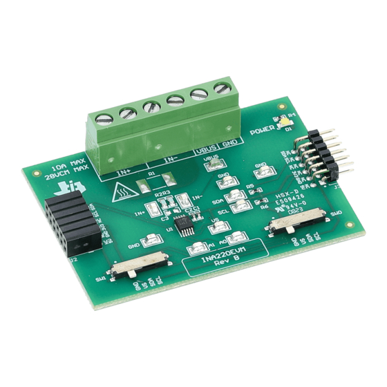
Related Documentation from Texas Instruments The INA220EVM is an evaluation module that is used to fully evaluate the INA220 current/power monitor device. The INA220EVM consists of two printed circuit boards (PCBs). One board (the USB DIG Platform) generates the digital signals required to communicate with the INA220, which is part of the second board (INA220_Test_Board), as well as support and configuration circuitry. - Page 3 The following document provides information regarding Texas Instruments integrated circuits used in the assembly of the INA220EVM. This user's guide is available from the TI web site under literature number SBOU079. Any letter appended to the literature number corresponds to the document revision that is current at the time of the writing of this document.
-
Page 4: System Setup
System Setup Figure 2 shows the system setup for the INA220EVM. The PC runs software that communicates with the USB DIG Platform. The USB DIG Platform generates the analog and digital signals used to communicate with the INA220_Test_Board. Connectors on the INA220_Test_Board allow the user to connect to the system under test whose power, current, and voltage will be monitored. -
Page 5: Ina220_Test_Board Schematic
A0 and A1. Connector T4 allows the connection of the shunt and bus voltages. Figure 4. INA220_Test_Board Schematic SBOU079B – July 2009 – Revised May 2016 INA220 Evaluation Module Submit Documentation Feedback Copyright © 2009–2016, Texas Instruments Incorporated... -
Page 6: Signal Definition Of J1 (25-Pin Male Dsub) On Ina220_Test_Board
No connection Common or ground connection for power SPI_SCK No connection SPI_CS1 No connection SPI_DOUT No connection SPI_DIN1 No connection INA220 Evaluation Module SBOU079B – July 2009 – Revised May 2016 Submit Documentation Feedback Copyright © 2009–2016, Texas Instruments Incorporated... -
Page 7: Usb_Dig_Platform Theory Of Operation
Figure 5 shows the block diagram for the USB DIG Platform. This platform is a general-purpose data acquisition system that is used on several different Texas Instruments evaluation modules. The details of its operation are included in a separate document (available for download at www.ti.com). -
Page 8: Ina220Evm Hardware Setup
INA220EVM Hardware Setup www.ti.com INA220EVM Hardware Setup The INA220EVM hardware setup involves connecting the two PCBs of the EVM together, applying power, connecting the USB cable, and setting the jumpers. This section presents the details of this procedure. Electrostatic Discharge Warning Many of the components on the INA220EVM are susceptible to damage by electrostatic discharge (ESD). -
Page 9: Connecting Power To The Evm
INA220EVM Hardware Setup www.ti.com Connecting the Hardware To connect the two PCBs of the INA220EVM together, gently push on both sides of the D-SUB connectors (as shown in Figure 7). Make sure that the two connectors are completely pushed together; loose connections may cause intermittent operation. -
Page 10: Connecting The Usb Cable
INA220EVM Hardware Setup www.ti.com Connecting the USB Cable to the INA220EVM Figure 8 shows the typical response to connecting the USB DIG platform to a PC USB port for the first time. Note that the EVM must be powered on before connecting the USB cable. Typically, the computer will respond with a Found New Hardware, USB Device pop-up. -
Page 11: Ina220Evm Default Jumper Settings
INA220 Jumper Settings Figure 9 shows the default jumpers configuration for the INA220EVM. In general, the jumper settings of the USB DIG Platform will not need to be changed. You may want to change some of the jumpers on the INA220_Test_Board to match your specific configuration. -
Page 12: Usb Dig Platform Jumper Settings
3V to 5V range will damage the EVM. JUMP18 Connects the pull-up on the GPIO to the V supply or the V supply. INA220 Evaluation Module SBOU079B – July 2009 – Revised May 2016 Submit Documentation Feedback Copyright © 2009–2016, Texas Instruments Incorporated... -
Page 13: Power-Supply Jumper Configuration #1
(U19, REG101) is used to generate a 3V supply for all digital I/O. JUMP14 = BUS JUMP1 = BUS JUMP2 = BUS JUMP6 = 3V JUMP7 = REG (ratiometric mode, 5V supply) SBOU079B – July 2009 – Revised May 2016 INA220 Evaluation Module Submit Documentation Feedback Copyright © 2009–2016, Texas Instruments Incorporated... -
Page 14: Ina220 Software Overview
INA220EVM Hardware Setup www.ti.com Connecting External Power to the INA220EVM The INA220 power supply (V ) operates over the range of 3V to 5.5V (see the INA220 product data sheet). The default jumper position provides 5V to the INA220 from the USB-DIG-Platform. The power from the USB-DIG-Platform can be changed to 3V using JUMP9. -
Page 15: Ina220Evm Software-Functioning Properly
INA220 Software Overview www.ti.com INA220EVM Software Install Follow these steps to install the INA220EVM software: Step 1. Software can be downloaded from the INA220EVM web page, or from the disk included with the INA220EVM, which contains a folder called Install_software/. -
Page 16: Ina220Evm Software-No Communication With The Usb Dig Platform
USB cable, the computer recognizes the device. If the sound is on, you will hear the distinctive sound that you expect when a USB device is properly connected to the PC. Figure 11. INA220EVM Software—No Communication with the USB DIG Platform INA220 Evaluation Module SBOU079B –... -
Page 17: Ina220Evm Software-No Communication With The Usb Dig Platform And Ina220
Another possible cause of this issue it that the INA220_Test_Board jumpers are set in the wrong position. Figure 12. INA220EVM Software—No Communication with the USB DIG Platform and INA220 SBOU079B – July 2009 – Revised May 2016... - Page 18 Using the INA220 Software The INA220EVM software has six different tabs that allow you to access different features of the INA220. The first four tabs are designed so that you can completely configure the device by stepping through the tabs in order.
-
Page 19: Evm Controls Drop-Down Menu
The Help...About feature can be used to check the current software revision, as Figure 14 illustrates. This document is based on revision 1.0.35. Figure 14. Current Software Revision SBOU079B – July 2009 – Revised May 2016 INA220 Evaluation Module Submit Documentation Feedback Copyright © 2009–2016, Texas Instruments Incorporated... -
Page 20: Bill Of Materials
Technology Inc 45°, 15A, Dove- tailed 3-pin connector 3-Position Terminal On-Shore ED300/3 Strip, Cage Clamp, Technology Inc 45°, 15A, Dove- tailed INA220 Evaluation Module SBOU079B – July 2009 – Revised May 2016 Submit Documentation Feedback Copyright © 2009–2016, Texas Instruments Incorporated... - Page 21 • Revised Table 3 ......................• Added Table 4 Table 5 ........................• Added Section 3.7 ........................• Added Section 3.8 SBOU079B – July 2009 – Revised May 2016 Revision History Submit Documentation Feedback Copyright © 2009–2016, Texas Instruments Incorporated...
- Page 22 STANDARD TERMS AND CONDITIONS FOR EVALUATION MODULES Delivery: TI delivers TI evaluation boards, kits, or modules, including any accompanying demonstration software, components, or documentation (collectively, an “EVM” or “EVMs”) to the User (“User”) in accordance with the terms and conditions set forth herein. Acceptance of the EVM is expressly subject to the following terms and conditions.
- Page 23 FCC Interference Statement for Class B EVM devices NOTE: This equipment has been tested and found to comply with the limits for a Class B digital device, pursuant to part 15 of the FCC Rules. These limits are designed to provide reasonable protection against harmful interference in a residential installation.
- Page 24 【無線電波を送信する製品の開発キットをお使いになる際の注意事項】 開発キットの中には技術基準適合証明を受けて いないものがあります。 技術適合証明を受けていないもののご使用に際しては、電波法遵守のため、以下のいずれかの 措置を取っていただく必要がありますのでご注意ください。 1. 電波法施行規則第6条第1項第1号に基づく平成18年3月28日総務省告示第173号で定められた電波暗室等の試験設備でご使用 いただく。 2. 実験局の免許を取得後ご使用いただく。 3. 技術基準適合証明を取得後ご使用いただく。 なお、本製品は、上記の「ご使用にあたっての注意」を譲渡先、移転先に通知しない限り、譲渡、移転できないものとします。 上記を遵守頂けない場合は、電波法の罰則が適用される可能性があることをご留意ください。 日本テキサス・イ ンスツルメンツ株式会社 東京都新宿区西新宿6丁目24番1号 西新宿三井ビル 3.3.3 Notice for EVMs for Power Line Communication: Please see http://www.tij.co.jp/lsds/ti_ja/general/eStore/notice_02.page 電力線搬送波通信についての開発キットをお使いになる際の注意事項については、次のところをご覧くださ い。http://www.tij.co.jp/lsds/ti_ja/general/eStore/notice_02.page SPACER EVM Use Restrictions and Warnings: 4.1 EVMS ARE NOT FOR USE IN FUNCTIONAL SAFETY AND/OR SAFETY CRITICAL EVALUATIONS, INCLUDING BUT NOT LIMITED TO EVALUATIONS OF LIFE SUPPORT APPLICATIONS.
- Page 25 Notwithstanding the foregoing, any judgment may be enforced in any United States or foreign court, and TI may seek injunctive relief in any United States or foreign court. Mailing Address: Texas Instruments, Post Office Box 655303, Dallas, Texas 75265 Copyright © 2015, Texas Instruments Incorporated...
- Page 26 IMPORTANT NOTICE Texas Instruments Incorporated and its subsidiaries (TI) reserve the right to make corrections, enhancements, improvements and other changes to its semiconductor products and services per JESD46, latest issue, and to discontinue any product or service per JESD48, latest issue.
Need help?
Do you have a question about the INA220EVM and is the answer not in the manual?
Questions and answers