Table of Contents
Advertisement
Quick Links
INA230EVM Evaluation Board and Software Tutorial
This user's guide describes the characteristics, operation, and use of the INA230EVM evaluation board. It
discusses how to set up and configure the software and hardware, and reviews various aspects of the
program operation. Throughout this document, the terms evaluation board, evaluation module, and EVM
are synonymous with the INA230EVM. This user's guide also includes information regarding operating
procedures and input/output connections, an electrical schematic, printed circuit board (PCB) layout
drawings, and a parts list for the EVM.
.....................................................................................................................
1
2
3
4
5
6
1
2
INA230EVM Hardware Setup
3
4
5
6
7
8
9
10
11
12
13
14
15
16
17
18
19
20
21
22
23
24
Microsoft, Windows are registered trademarks of Microsoft Corporation.
2
I
C is a trademark of NXP Semiconductors.
WinZIP is a registered trademark of WinZip International LLC.
All other trademarks are the property of their respective owners.
SBOU124 - March 2012
Submit Documentation Feedback
.............................................................................................
.....................................................................................................
.............................................................................................
.........................................................................................
.............................................................................................
.................................................................................
.............................................................................................
.................................................................................
...................................................................................
....................................................................................
........................................................................................................
............................................................................................
.......................................................................................
.......................................................................................
.........................................................................................
...................................................................................................
.............................................................................................
...........................................................................................
..................................................................................................
.......................................................................................................
..............................................................................................................
Copyright © 2012, Texas Instruments Incorporated
Contents
List of Figures
.............................................................
.............................................................
.............................................................
...........................................................................
............................................................
.....................................................................
..............................................................
INA230EVM Evaluation Board and Software Tutorial
User's Guide
SBOU124 - March 2012
....................................
3
4
6
12
15
23
3
4
4
5
7
8
8
9
11
11
12
13
14
15
16
17
18
18
19
19
19
20
20
21
1
Advertisement
Table of Contents

Subscribe to Our Youtube Channel
Related Manuals for Texas Instruments INA230EVM


Summary of Contents for Texas Instruments INA230EVM
-
Page 1: Table Of Contents
SBOU124 – March 2012 INA230EVM Evaluation Board and Software Tutorial This user's guide describes the characteristics, operation, and use of the INA230EVM evaluation board. It discusses how to set up and configure the software and hardware, and reviews various aspects of the program operation. - Page 2 INA230EVM PCB Top Layer (Component Side) List of Tables ....................INA230EVM Kit Contents ....................Related Documentation ................Signal Definition of J1 on INA230EVM Board ................INA230EVM Test Board Jumper Functions ..................INA230 I C Address Configuration ................... Bill of Materials: INA230EVM INA230EVM Evaluation Board and Software Tutorial SBOU124 –...
-
Page 3: Overview
C™ interface. The INA230 monitors both current and supply voltage, with programmable conversion times and averaging modes. The INA230EVM is a platform for evaluating the performance of the INA230 under various signal, shunt, and supply conditions. This document gives a general overview of the INA230EVM, and provides a general description of the features and functions to be considered while using this evaluation module. -
Page 4: Ina230Evm Hardware Setup
The following documents provide information regarding Texas Instruments' integrated circuits used in the assembly of the INA230EVM. This user's guide is available from the TI web site under literature number SBOU124. Any letter appended to the literature number corresponds to the document revision that is current at the time of the writing of this document. -
Page 5: Sm-Usb-Dig Platform Block Diagram
Table 3 lists the pinout for the 10-pin connector socket used to communicate between the INA230EVM and the SM-USB-DIG. It should be noted that the INA230EVM only uses the necessary I communication lines (pins 1 and 3) and the V and GND pins (pin 6 and pin 8) to issue commands to the INA230 chip. -
Page 6: Ina230Evm Hardware
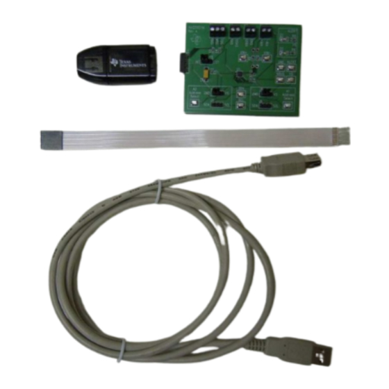
ESD workstation. Connecting the Hardware To set up the INA230EVM and connect the two PCBs of the EVM together (that is, the INA230 Test Board and SM-USB-DIG Platform board), gently slide the male and female ends of the 10-pin connectors together. -
Page 7: Typical Hardware Test Connections For The Ina230Evm
The external power source is connected to the terminal strip T3. NOTE: It is always necessary to connect the power to the SM-USB-DIG Platform board before connecting the USB cable. Figure 5. Typical Hardware Test Connections for the INA230EVM SBOU124 – March 2012 INA230EVM Evaluation Board and Software Tutorial Submit Documentation Feedback Copyright ©... -
Page 8: Connecting The Usb Cable To The Sm-Usb-Dig Platform
Windows then confirms installation of the drivers with the message shown in Figure Figure 7. Confirmation of SM-USB-DIG Platform Driver Installation INA230EVM Evaluation Board and Software Tutorial SBOU124 – March 2012 Submit Documentation Feedback Copyright © 2012, Texas Instruments Incorporated... -
Page 9: Ina230Evm Default Jumper Settings
Figure 8. INA230EVM Default Jumper Settings Typically, jumper 2 on the INA230EVM is always set to the INT position. When set to the INT position, the SM-USB-DIG Platform provides the supply for the INA230. When this jumper is set to the EXT position, an external supply voltage can be connected to terminal strip T2 to provide the supply for the INA230. - Page 10 SM-USB-DIG and the terminal block T1. If the user wants to add external signals separate from the SM-USB-DIG, simply disconnect the SM-USB-DIG from the INA230EVM board and hook up the necessary SDA, SCL, and GND lines. Also, remember to apply an external supply to the lines that is compatible with the I C communication device being used.
-
Page 11: Typical Filter Setup
VIN+ and VIN– Input filter (R1, R2, and C1) The INA230EVM has an optional input filter to remove high-frequency noise from the inputs VIN+ and VIN–. This filter is typically unpopulated. The default values for R1 and R2 are 0-Ω resistors. -
Page 12: Ina230Evm Software Setup
United States and European regional settings. The software should also function on other Windows OS platforms. Software Installation The INA230EVM software is included on the CD that is shipped with the EVM kit. It is also available through the INA230EVM product folder on www.ti.com. -
Page 13: Ina230Evm License Agreements
Instruments\. Following this option, two license agreements are presented that must be accepted, as shown in Figure 12. After accepting the Texas Instruments and National Instruments license agreements, the progress bar opens and shows the installation of the software, as Figure 13 illustrates. -
Page 14: Ina230Evm Software Installation Progress
INA230EVM Software Setup www.ti.com Figure 13. INA230EVM Software Installation Progress INA230EVM Evaluation Board and Software Tutorial SBOU124 – March 2012 Submit Documentation Feedback Copyright © 2012, Texas Instruments Incorporated... -
Page 15: Ina230Evm Software Overview
INA230EVM Software Overview www.ti.com INA230EVM Software Overview This section discusses how to use the INA230EVM software. Software operation involves a two-step process: configuration of the INA230 settings, and operation of the tool. Starting the INA230EVM Software The INA230 software can be operated through the Windows Start menu. From Start, select All Programs;... -
Page 16: Ina230Evm Software: Communication Error With The Sm-Usb-Dig Platform
Figure 15. INA230EVM Software: Communication Error with the SM-USB-DIG Platform Configuring the INA230EVM Software The INA230EVM software first requires a series of setup processes to configure the device and ensure that it works properly. On the Configuration tab (see Figure 14), there are six steps noted: Step 1. -
Page 17: Setting The A1 Address
5.2.2 Configure Operating Mode The second step of the INA230EVM configuration process allows the user to set the operating mode and the averaging mode. The Operating mode allows the user to restrict the amount of calculations done within the INA230 by changing the conversion to be triggered or continuous, or shutting down the part altogether. -
Page 18: Configuring Operating Mode
Setting the conversion times allows the user to customize the amount of measurement time for conversions. Typically, for the INA230EVM software, the user is not able to notice a visual difference between the conversion times unless a high averaging mode and conversion time are chosen. The Shunt... -
Page 19: Setting The Configuration Register (Calibration Register)
Limit box. This Alert Limit box modifies its functionality based on the selected configuration. It is important to note that by default, the INA230 Alert pin is set to active low. Figure 21. Configuring the Alert Pin SBOU124 – March 2012 INA230EVM Evaluation Board and Software Tutorial Submit Documentation Feedback Copyright © 2012, Texas Instruments Incorporated... -
Page 20: Ina230 Results Bar
INA230 conversion process. Using the INA230EVM Software After configuring the INA230EVM software, the rest of the tabs can be evaluated. This section describes the basic operation of the device, and offers guidelines for interpreting the graphic user interface (GUI). -
Page 21: Registers Tab
Figure 24, the user can diagnose the individual uses of each bit in each register. Figure 24. Registers Tab SBOU124 – March 2012 INA230EVM Evaluation Board and Software Tutorial Submit Documentation Feedback Copyright © 2012, Texas Instruments Incorporated... - Page 22 Auto-Write and the Supply Voltage The INA230EVM software allows users to customize the board level voltage, regulated by the SM-USB- DIG. By selecting either 3.3 V or 5 V, the user can designate which voltage the device should operate at.
-
Page 23: Ina230Evm Documentation
This section contains the complete bill of materials, schematic diagram, and PCB layout for the INA230EVM. NOTE: The board layout is not to scale. This image is intended to show how the board is laid out; it is not intended to be used for manufacturing INA230EVM PCBs. Schematic Figure 27 shows the schematic for the INA230EVM. - Page 24 INA230EVM Documentation www.ti.com PCB Layout Figure 28 shows the component layout for the INA230EVM PCB. Figure 28. INA230EVM PCB Top Layer (Component Side) INA230EVM Evaluation Board and Software Tutorial SBOU124 – March 2012 Submit Documentation Feedback Copyright © 2012, Texas Instruments Incorporated...
- Page 25 INA230EVM Documentation www.ti.com Bill of Materials Table 6 lists the bill of materials for the INA230EVM. Table 6. Bill of Materials: INA230EVM Item No. Ref Des Description Vendor/Mfr Part Number R5, R6 Resistor, 10 kΩ 1/10 W 5% 0603 SMD...
- Page 26 Evaluation Board/Kit Important Notice Texas Instruments (TI) provides the enclosed product(s) under the following conditions: This evaluation board/kit is intended for use for ENGINEERING DEVELOPMENT, DEMONSTRATION, OR EVALUATION PURPOSES ONLY and is not considered by TI to be a finished end-product fit for general consumer use. Persons handling the product(s) must have electronics training and observe good engineering practice standards.
- Page 27 IMPORTANT NOTICE Texas Instruments Incorporated and its subsidiaries (TI) reserve the right to make corrections, modifications, enhancements, improvements, and other changes to its products and services at any time and to discontinue any product or service without notice. Customers should obtain the latest relevant information before placing orders and should verify that such information is current and complete.
Need help?
Do you have a question about the INA230EVM and is the answer not in the manual?
Questions and answers