Table of Contents
Advertisement
Quick Links
INA223EVM User's Guide and Software Tutorial
This user's guide describes the characteristics, operation, and use of the INA223EVM evaluation board. It
discusses how to set up and configure the software and hardware, and reviews various aspects of the
program operation. This user's guide also includes information regarding operating procedures and
input/output connections, an electrical schematic, printed circuit board (PCB) layout drawings, and a parts
list for the EVM.
Throughout this document, the terms evaluation board, evaluation module, and EVM are synonymous with
the INA223EVM.
Microsoft, Windows are registered trademarks of Microsoft Corporation.
SPI is a trademark of Motorola Inc,.
2
I
C is a trademark of NXP Semiconductors.
SBOU125 – June 2012
Submit Documentation Feedback
INA223EVM
Copyright © 2012, Texas Instruments Incorporated
INA223EVM User's Guide and Software Tutorial
User's Guide
SBOU125 – June 2012
1
Advertisement
Table of Contents

Related Manuals for Texas Instruments INA223EVM


Summary of Contents for Texas Instruments INA223EVM
- Page 1 INA223EVM User’s Guide and Software Tutorial INA223EVM This user's guide describes the characteristics, operation, and use of the INA223EVM evaluation board. It discusses how to set up and configure the software and hardware, and reviews various aspects of the program operation. This user's guide also includes information regarding operating procedures and input/output connections, an electrical schematic, printed circuit board (PCB) layout drawings, and a parts list for the EVM.
-
Page 2: Table Of Contents
Hardware Setup ..................INA223 Test Board Block Diagram ................... SM-USB-DIG Platform Block Diagram .............. Typical Hardware Test Connections on the INA223EVM ............. Connecting the USB Cable to the SM-USB-DIG Platform ............. Confirmation of SM-USB-DIG Platform Driver Installation ..................... INA223EVM Default Jumpers ...................... -
Page 3: Ina223Evm (Continued)
The INA223 is a voltage output device that monitors current, bus voltage, and power of a supply line by sensing a voltage drop across a shunt. The INA223EVM is a platform for evaluating the performance of the INA223 under various signal, shunt, and supply conditions. This document gives a general overview of the INA223EVM, and provides a general description of the features and functions to be considered while using this evaluation module. -
Page 4: Ina223Evm Hardware Setup
The following document provides information regarding Texas Instruments integrated circuits used in the assembly of the INA223EVM. This user's guide is available from the TI web site under literature number SBOU125 . Any letter appended to the literature number corresponds to the document revision that is current at the time of the writing of this document. -
Page 5: Ina223 Test Board Block Diagram
10-pin connector socket used to communicate between the INA223EVM and the SM-USB-DIG. It should be noted that to issue commands to the INA223 chip, the INA223EVM only uses H1 connnector pins 1 and 3 (I C communication lines), pin 6 (VDUT), and pin 8 (GND). -
Page 6: Sm-Usb-Dig Platform Block Diagram
SM-USB-DIG Platform. This platform is a general-purpose data acquisition system that is used on several different Texas Instruments evaluation modules. The details of its operation are included in a separate document (SBOU098). The block diagram shown in Figure 4 given as a brief overview of the SM-USB-DIG Platform. -
Page 7: Ina223Evm Hardware Overview
USB cable, and setting the jumpers. This section describes the details of this procedure. Electrostatic Discharge Warning Many of the components on the INA223EVM are susceptible to damage by electrostatic discharge (ESD). Customers are advised to observe proper ESD handling precautions when unpacking and handling the EVM, including the use of a grounded wrist strap at an approved ESD workstation. -
Page 8: Connecting The Usb Cable To The Sm-Usb-Dig Platform
Figure 7. This pop-up indicates that the device is ready to be used. Figure 7. Confirmation of SM-USB-DIG Platform Driver Installation INA223EVM User’s Guide and Software Tutorial SBOU125 – June 2012 Submit Documentation Feedback Copyright © 2012, Texas Instruments Incorporated... -
Page 9: Ina223Evm Default Jumpers
C address by configuring jumper 1 (JMP1) and jumper 2 (JMP2). Figure 8. INA223EVM Default Jumpers Jumper 3 (JMP3) on the INA223EVM is typically set to the internal (INT) position. When set to the INT position, the device supply voltage is generated and controlled from the SM-USB-DIG Platform. When this... - Page 10 C lines and Terminal Block T3 The I C communication lines on the INA223EVM are tied to two sources: The internal I C communication lines from the SM-USB-DIG Platform and terminal block T3. If external signals separate from the SM-USB- DIG are to be used, simply disconnect the SM-USB-DIG from the INA223 board and connect to external SDA, SCL, and GND lines.
-
Page 11: Typical Filter Setup
V Input Filter (R4, R3, and C3) IN– The INA223EVM has an optional input filter located between the terminal block T2 and the INA223 input pins. This filter helps to remove high-frequency noise from the V and V inputs. The EVM ships with IN–... -
Page 12: Ina223Evm Software Setup
INA223 Software Installation The INA223EVM software is included on the CD that is shipped with the EVM kit. It is also available through the INA223EVM product folder on the TI web site. To download the software to your system, insert the disc into an available CD-ROM drive. -
Page 13: Software License Agreement
Figure Figure 12. Software License Agreement After accepting the Texas Instruments and National Instruments license agreements, the progress bar opens and shows the installation of the software, as shown in Figure 13. -
Page 14: Ina223Evm Software Overview
INA223EVM Software Overview www.ti.com INA223EVM Software Overview This section describes how to use the INA223EVM software. The software operation contains a two-step process: configuration and operation. Starting the INA223EVM Software To start the INA223 software, go to the Windows Start menu, select All Programs, and then select the INA223EVM program. -
Page 15: Setting The A0 Address
EVM. If the correct address is not selected, the INA223 cannot communicate with the software. Figure 16. Setting the A0 Address SBOU125 – June 2012 INA223EVM User’s Guide and Software Tutorial Submit Documentation Feedback Copyright © 2012, Texas Instruments Incorporated... -
Page 16: Configuring The Output Mode
Figure 17. Configuring the Output Mode The two power output modes of the INA223EVM is used to select whether the signal representing the power being supplied by the power supply or the power being consumed by the load is made available at the output pin. -
Page 17: Power Gain Values
Section 5.2.3 Section 5.2.4. NOTE: For maximum accuracy, select a gain that gives a full-scale voltage, just below the maximum output voltage. SBOU125 – June 2012 INA223EVM User’s Guide and Software Tutorial Submit Documentation Feedback Copyright © 2012, Texas Instruments Incorporated... -
Page 18: Configuring The Bus Voltage Gain
Failure to ensure that the outputs are within the linear range of the device can result in inaccurate results. Figure 19. Configuring the Current Shunt Voltage Gain INA223EVM User’s Guide and Software Tutorial SBOU125 – June 2012 Submit Documentation Feedback... -
Page 19: Register Table
Help w Reg button (shown in Figure 20), the individual use of each bit in each register can be diagnosed. Figure 20. Register Table SBOU125 – June 2012 INA223EVM User’s Guide and Software Tutorial Submit Documentation Feedback Copyright © 2012, Texas Instruments Incorporated... -
Page 20: Auto-Write, Power, And Voltage Controls
Auto-Write and DVDD Voltage The INA223EVM software allows for customization of the board level voltage, regulated by the SM-USB- DIG. Select either +3.3V or +5V for the operating voltage of the chip, as shown in the upper red box in Figure Figure 21. -
Page 21: Example Hardware Calculator
5.3.3 Example Hardware Calculator The Example Hardware Calculator tab allows the user to simulate the analog results of the INA223EVM. By adjusting the controls on this page, and entering inputs for Vin+ (V), Vin- (V), and Rshunt, the approximate values for Vout (V) and Power (W) can be estimated. Note that the appropriate output mode must be selected to ensure accurate results, and that no limitations of the device are violated in the Error field. -
Page 22: Ina223Evm Documentation
This section contains the complete bill of materials, schematic diagram, and PCB layout for the INA223EVM. Documentation information for the SM-USB-DIG Platform can be found in the SM-USB-DIG Platform User’s Guide (SBOU058), available at the TI web site at http://www.ti.com. -
Page 23: Ina223Evm Board Schematic
INA223EVM Documentation www.ti.com Schematic Figure 23 shows the schematic for the INA223EVM board. 0&' 0#&' *-. ) 3 3 45 0&' 0&' ! =; & $$ 0#&' 0#&' ! =; & $$ $<& $<& ! =; & $$ ' ; $! ' 336 1 &;... -
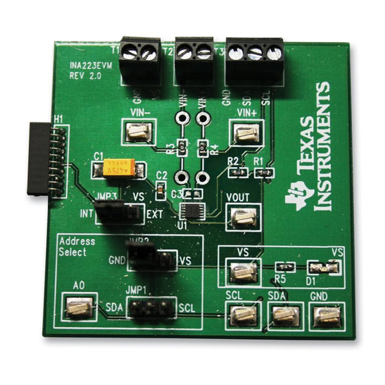
Page 24: Ina223Evm Pcb Component Layout
INA223EVM Documentation www.ti.com PCB Component Layout Figure 24 shows the layout of the components for the INA223EVM PCB. Figure 24. INA223EVM PCB Component Layout INA223EVM User’s Guide and Software Tutorial SBOU125 – June 2012 Submit Documentation Feedback Copyright © 2012, Texas Instruments Incorporated... - Page 25 Evaluation Board/Kit Important Notice Texas Instruments (TI) provides the enclosed product(s) under the following conditions: This evaluation board/kit is intended for use for ENGINEERING DEVELOPMENT, DEMONSTRATION, OR EVALUATION PURPOSES ONLY and is not considered by TI to be a finished end-product fit for general consumer use. Persons handling the product(s) must have electronics training and observe good engineering practice standards.
- Page 26 IMPORTANT NOTICE Texas Instruments Incorporated and its subsidiaries (TI) reserve the right to make corrections, modifications, enhancements, improvements, and other changes to its products and services at any time and to discontinue any product or service without notice. Customers should obtain the latest relevant information before placing orders and should verify that such information is current and complete.
Need help?
Do you have a question about the INA223EVM and is the answer not in the manual?
Questions and answers