Table of Contents
Advertisement
Quick Links
80 and 40 Meter
DX Engineering
Thunderbolt
™
Dual Band
Vertical Antenna
DXE-8040VA-1
US Patent No. 8,130,168
DXE-8040VA-1-INS Revision 4a
© DX Engineering 2012
P.O. Box 1491 ∙ Akron, OH 44309-1491 USA
Phone: (800) 777-0703 ∙ Tech Support and International: (330) 572-3200
Fax: (330) 572-3279 ∙ E-mail: DXEngineering@DXEngineering.com
Advertisement
Table of Contents

Related Manuals for DX Engineering DXE-8040VA-1


Summary of Contents for DX Engineering DXE-8040VA-1
- Page 1 Dual Band Vertical Antenna DXE-8040VA-1 US Patent No. 8,130,168 DXE-8040VA-1-INS Revision 4a © DX Engineering 2012 P.O. Box 1491 ∙ Akron, OH 44309-1491 USA Phone: (800) 777-0703 ∙ Tech Support and International: (330) 572-3200 Fax: (330) 572-3279 ∙ E-mail: DXEngineering@DXEngineering.com...
-
Page 2: Table Of Contents
80/40 Trap Assembly and Installation Base Matching Network Assembly and Installation Optional DXE-7580-THK Capacity Hat Assembly and Installation Tuning the Vertical Operation of the DXE-8040VA-1 for CW portion of the 80M band Locking the Pivot Base DXE-8040VA-1 Part Lists Pivot Base Assembly... -
Page 3: Introduction & Features
Easy to add to or remove from upper antenna mast with two studded element clamps after lowering antenna. The DX Engineering DXE-8040VA-1 is a slow taper 53 to 55-foot high Dual Band Vertical Antenna system. The vertical antenna is specifically designed to operate on 80 meters and 40 meters. -
Page 4: Warning
The optional DXE-VRW-1 Manual Winch for easy one-person raising and lowering of the antenna is available from DX Engineering. You can move the DXE-VRW-1 winch between similar antennas in a multi-antenna installation. This antenna system requires a heavy duty mounting pipe. Recommended installation should provide up to 3"... -
Page 5: Manual Updates And Information
Every effort is made to supply the latest manual revision with each product. Occasionally a manual will be updated between the time your DX Engineering product is shipped and when you receive it. Please check the DX Engineering web site (www.dxengineering.com) for the latest revision manual. -
Page 6: Coaxial Cable To Mounting Pipe
Metals Depot: www.metalsdepot.com Note: DX Engineering does not recommend or endorse any specific vendor. This mounting pipe must be permanently mounted in the ground, preferably in a concrete base 2 feet by 2 feet by 4 feet deep (with gravel below for drainage). The antenna system requires this type... -
Page 7: Radial System
Grass will quickly overgrow the radials and it will be virtually impossible to see them. An article describing this process is available on the DX Engineering website in the Tech Info section. Radials can also be buried just under the surface by using a power edger to make a slit in the soil. -
Page 8: Radial Plate To Mounting Pipe
Note: The following assembly instructions are based on using a customer supplied 2.895" OD Mounting Pipe, with the optional DXE-VR-1 Manual Winch, optional DXE-RADP-3 Radial Plate, optional DXE-363-SST Bulkhead Connector and the optional DXE-7580-THK Capacity Hat Assembly. Radial Plate to Mounting Pipe Place the optional DXE-RADP-3 Radial Plate over the 2.895"... -
Page 9: Attaching Ground Radial Wires To The Radial Plate
Additional hardware kits are available (DXE-RADP-1HWK) that contain 20 sets of Radial Plate Hardware. There are optional DX Engineering Radial Wire Kits available. DXE-RADW-500K/BD contains a 500 foot spool of 14 gauge copper stranded wire with black PVC insulation, 20 Terminal Lugs and 100 Steel or Biodegradable Lawn Staples. -
Page 10: Overall Pivot And Antenna Base Assembly Drawing
Overall Pivot Base (US Patent No. 8,130,168) Assembly Drawing The exploded view drawing is for reference and shows the overall Pivot Base Assembly. - 9 -... -
Page 11: Pivot Base And Lower Antenna Assembly
Pivot Base and Lower Antenna Assembly 1. Locate the heavy duty Extren® insulated channel. There are 12 holes drilled in the insulated channel. The top of the insulated channel is identified by two holes located very near the top side. 2. - Page 12 4. Locate the stainless steel base side bottom hinge, two 1/2-13 x 1-1/4" long stainless steel hex head bolts, two pivot bushings, four 1/2 x 1-1/4" stainless steel flat washers, two 1/2" stainless steel split lock washers, and two 1/2-13 stainless steel hex nuts. Assemble the base side hinge plate to the bottom hinge plate as shown below.
- Page 13 6. Locate the stainless steel Pivot Base Winch Mount, two stainless steel Pivot Base Plate Brackets, four 3/8-16 x 1-1/4" long stainless steel hex bolts, eight stainless steel 3/8" flat washers, four stainless steel 3/8" split lock washers and four stainless steel 3/8-16 hex nuts. Assemble the Pivot Base Plate Brackets to the Pivot Base Winch Mount as shown below.
- Page 14 8. Locate two V-Saddle blocks, two stainless steel V-Bolts, four stainless steel 3/8" flat washers, four stainless steel 3/8" split lock washers and four stainless steel 3/8-16 hex head nuts. Loosely assemble (one or two threads beyond the end of the hex nuts) the two V-Bolts to the stainless steel Pivot Base Winch Mount as shown below.
- Page 15 10. Move the four V-Bolts out as far as they will go (these were put on loosely in steps 2 and 8). Slide the entire assembly onto your mounting pipe. You want approximately 1 inch clearance from the top of your mounting pipe to the bottom side of the winch mounting plate. Position the base fixture in the position you pre-selected for the pivoting direction.
- Page 16 11. Locate the 3" OD x 72", 0.120 wall thickness antenna bottom element section. There are 5 holes drilled in this element section. One drilled hole at the bottom is for the feedpoint hardware. Four drilled holes at the top are used for mating to the next antenna element section.
- Page 17 12. Locate the stainless steel Antenna Hook Mounting Plate, two U-Bolt Saddle blocks, two stainless steel U-Bolts, four stainless steel 3/8" flat washers, four stainless steel 3/8" split lock washers and four stainless steel 3/8-16 hex head nuts. Loosely assemble (one or two threads beyond the end of the hex nuts) the two U-Bolts and associated hardware to the antenna hook mounting plate as shown below.
- Page 18 14. Tighten the two U-Bolt clamps hardware evenly so the length of the exposed threads is approximately equal. Any clamp should be tightened evenly from side-to-side with an equal amount of thread above each nut. 15. Locate the 1/4-20 x 1" long stainless steel hex bolt, three 1/4" stainless steel external tooth lock washers, two 1/4"...
-
Page 19: Mounting And Using The Optional Dxe-Vrw-1 Manual Winch
Mounting and using the Optional DXE-VRW-1 Manual Winch 1. Follow the instructions included with the optional DXE-VRW-1 - Manual Winch Add-On Kit to prepare the Manual Winch for installation on the antenna base assembly. 2. Included with optional DXE-VRW-1 - Manual Winch Add-On Kit is the stainless steel hardware for mounting the winch on the pivot base assembly. - Page 20 There are three holes with slots in the mounting bracket. The flat washers will fit through the large holes. Once in place, push the winch inward (toward the antenna elements) allowing the three bolts to go into the three slots. Tighten the hardware to hold the winch in place. Connect the Hook from the manual winch strap to the Antenna Hook Mount as shown below.
- Page 21 3. To lower the antenna, ensure the winch hook is in the Antenna Hook Mount. Remove the four bolts and hardware that hold the Pivot Lock Plate to the Pivot Base Winch Mount Plate. You can now use the winch to pivot the antenna downward. Four Bolts to be removed to allow for pivoting 4.
-
Page 22: General Information About Aluminum Tubing
Deburring is a finishing method used in manufacturing. Our aluminum tubing is machine cut on both ends and machine slit on one end. Although DX Engineering manufactured aluminum tubing is deburred, you should further assure that there are no ragged edges or protrusions. -
Page 23: Assembling The Vertical Sections
5. When assembling the aluminum tubing sections, ensure the area is clear of grass, dirt or other foreign material that could cause problems during assembly of the closely fitted telescoping sections. Assembling the Vertical Sections Note: DXE-P8A -Penetrox™ A Anti-Oxidant should be used between all antenna element sections. - Page 24 DXE-8040VA-1 Element Sections Note: The 3" OD x 72" long, 0.120 wall thickness base antenna section has already been installed on the Pivot Base Assembly. - 23 -...
- Page 25 2. Locate the following hardware: Description 1/4" x 2-34" long Stainless Steel Hex Head Bolt 1/4" x 3" long Stainless Steel Hex Head Bolt 1/4" x 3-1/4" long Stainless Steel Hex Head Bolt 1/4" Stainless Steel Flat Washer 1/4" Stainless Steel Nyloc Hex Nut 3.
- Page 26 4. Assemble the 2.5" OD element to the 2.75" OD element using the two stainless steel 3-1/4" long 1/4" bolts, four stainless steel flat washers and two 1/4" stainless steel Nyloc nuts as shown below. Make sure you insert the 2.5” OD tube into the correct end of the 2.75” OD section - the holes at each end are drilled differently.
- Page 27 7. Using a tape measure and felt tip pen, four of the 72" long slit tubing elements need to be marked as follows: The 1.75" OD element is marked 16" from the end without the slit. The 1.25" OD element is marked 4" from the end without the slit. The 1.125"...
- Page 28 9. The five slit elements are installed using Stainless Steel Element Clamps. The drawing below shows the exposed lengths for reference. The reference drawing below shows the hardware used for joining the slit elements. 10. Locate two DXE-ECL-24SS Stainless Steel Element Clamps, one DXE-ECL-20SS Stainless Steel Element Clamp and the 1.75"...
- Page 29 11. Locate the Insulator, one DXE-ECL-20SS Stainless Steel Element Clamp, one DXE-ECL- 16SS Stainless Steel Element Clamp and the 1.5" OD x 72 long element that has slits at both ends. Slide the DXE-ECL-20SS over the 1.75" OD element. Slide the DXE-ECL-16SS over the 1.5" OD element.
- Page 30 14. Locate the DXE-ECL-10SS Stainless Steel Element Clamp, the 1" OD x 72" element that was marked in step 7 and the Black Vinyl Cap. Slide the DXE-ECL-10SS element clamp over the 1.125" OD element. Slide the 1" OD element inside the 1.125" OD element to the mark made at 20".
-
Page 31: Mating The Vertical Elements To The Pivot Base Assembly
Mating the Vertical Element to the Pivot Base Assembly 1. To lower the antenna, ensure the winch hook is in the Antenna Hook Mount. Remove the four bolts and hardware that hold the Pivot Lock Plate to the Pivot Base Winch Mount Plate. You can now use the winch to pivot the antenna downward. -
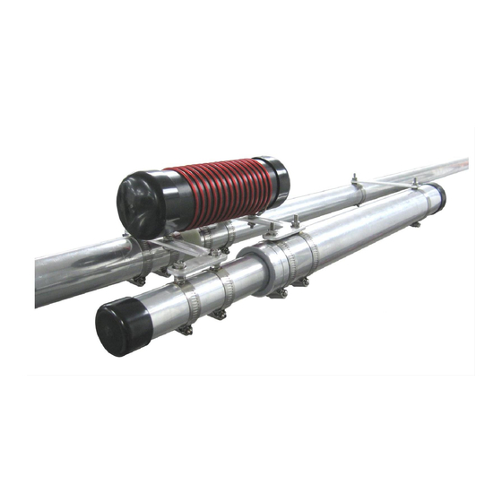
Page 32: 80/40 Trap Assembly And Installation
3. Assemble the 2.75" OD element to the 3" OD element using the two stainless steel 3-1/4" long 1/4" bolts, four stainless steel flat washers and two 1/4" stainless steel Nyloc nuts as shown below. When tightening the bolt and Nyloc nut, tighten them enough to hold, but not tight enough to deform the aluminum elements. - Page 33 1. Install the 2.25" studded clamp on the Antenna Straight Bracket using a #10 stainless steel flat washer, #10 stainless steel split washer, #10 stainless steel external tooth lock washer and a stainless steel 10-24 hex nut as shown. 2. Install the antenna straight bracket with clamp on the trap approximately 17" from the end of the larger tube as shown below.
- Page 34 3. Using the stainless steel hardware, install one 1.5" studded clamp on the straight bracket as shown above. Install one 1.5" and one 1.75" studded clamp on the trap brackets as shown above. Unscrew (or open) the three element clamps (two 1.5" and one 1.75" clamps) to allow easy installation of the 80/40 trap assembly on the antenna in the next step.
-
Page 35: Base Matching Network Assembly And Installation
Base Matching Network Assembly and Installation Base Matching Network Assembly Description Custom made base loading coil assembly with wire & Coil Tap Clip 1/4" Flat Washer 1/4" Split Lock Washer 1/4"-16 Nut In areas where there is a high atmospheric static condition (areas prone to precipitation or snow static) this antenna (as with all antennas) will build up a static charge. -
Page 36: Optional Dxe-7580-Thk Capacity Hat Assembly And Installation
Optional Capacity Hat Assembly and Installation This patented add-on kit for the DXE-8040VA-1 high performance DX Engineering THUNDERBOLT vertical antenna allows the center of resonance to be moved down to the low band edge for dedicated CW operations. If you do not install it, skip this section and proceed to the Tuning section of this manual. - Page 37 1. Locate the two 1-1/4" studded element clamps, the Top Hat "L" Bracket, two #10 stainless steel star washers, two #10 stainless steel split washers, two #10 stainless steel washers and two #10 stainless steel hex nuts. Assemble the studded element clamps to the "L" bracket as shown below.
- Page 38 4. Locate the patented Smooth Hub and two #8-32 x 1/4" long Stainless Steel Screw - Cup Point Allen screws. Using the supplied 5/64" Allen Wrench screw the 1/4" long Allen screws in the smooth hub in the two places as shown below. Only put these Allen Screws in half way, they will be tightened in a later step.
-
Page 39: Tuning The Vertical
7. Locate and install the six plastic end caps on the ends of the Hot Rodz Tuning the Vertical Tuning the DXE-8040VA-1 80/40 Meter Vertical Antenna is straightforward and intuitive. If you use an SWR meter or an analyzer at the base of the antenna you will get the most accurate readings in a timely fashion. - Page 40 Note: During the following adjustments Do Not Make any Adjustment to the Trap. Note: For the purposes of these instructions the term “resonance” or “resonant frequency” is defined as the point of lowest SWR and may be used interchangeably. To adjust the low SWR point in the 40 meter band, merely adjust the length of the tubing section just below the trap assembly in the normal manner, i.e., making it longer lowers the 40M resonant Frequency and shortening it raises the frequency.
-
Page 41: Operation Of The Dxe-8040Va-1 For Cw Portion Of The 80M Band
Operation of the DXE-8040VA-1 for CW portion of the 80M band To optimize the DXE-8040VA-1 for operation near the bottom of the 80M band, add the optional patented capacity Top Hat Kit model DXE-7580-THK. Assemble the Top Hat and install it at the position shown in the diagram below. -
Page 42: Dxe-8040Va-1 Part Lists
DXE-8040VA-1 Parts List Pivot Base Assembly - US Patent No. 8,130,168 Description Base Side Bottom Hinge Antenna Side Bottom Hinge Bottom Hinge Bushing Heavy Duty Antenna Insulator Channel Saddle Backing Plate 1/4” Antenna Pivot Hook Mount Pivot Base Winch Mount... -
Page 43: Vertical Elements Assembly
Vertical Elements Assembly Description 3" OD x 72" long, .120" wall, 5 drilled holes 2.75" OD x 48" long, .120 wall, 8 drilled holes 2.5" OD x 72" long, .120 wall, 8 drilled holes 2.25" OD x 72" long, .120 wall, 8 drilled holes 2"... -
Page 44: Optional Dxe-7580-Thk Capacity Hat Assembly
Optional DXE-7580-THK Capacity Hat Assembly Description Smooth Hub (US Patent No. 7,002,525) 0.5" Mast Tube Connector Fitting #8-32 x 1/8" long Stainless Steel Allen Screw - Cup Point #8-32 x 1/4" long Stainless Steel Allen Screw - Flat Point ® Hot Rodz - .125"... -
Page 45: Suggested Parts Not Included
Made from Laser Cut Stainless Steel with 20 Sets of Stainless Steel Radial Attachment Hardware. The DX Engineering Radial Plate is meant for those of you having a vertical antenna and want an easy, neat and effective way to connect those essential radial wires to your antenna system for the highest efficiency and strongest signals. -
Page 46: Optional Accessory Items
Optional Accessory Items UMI-81343, DXE-NSBT8 - Anti-Seize & Never-Seez® An Anti-seize compound MUST be used on any Stainless Steel nuts, bolts, clamps or other hardware to prevent galling and thread seizure. Any of these products can be used for this purpose. *UMI-81343 Anti-Seize, 1 oz. - Page 47 DXE-STPL - Radial Wire Anchor Pins, 100/pack - No need to bury your radials! DX Engineering Radial Wire Anchor Pins are perfect for fastening radials below the grass line to eliminate the risk of damaging your radials during lawn maintenance.
-
Page 48: Technical Support And Warranty
All products manufactured by DX Engineering are warranted to be free from defects in material and workmanship for a period of one (1) year from date of shipment. DX Engineering’s sole obligation under these warranties shall be to issue credit, repair or replace any item or part thereof which is proved to be other than as warranted; no allowance shall be made for any labor charges of Buyer for replacement of parts, adjustment or repairs, or any other work, unless such charges are authorized in advance by DX Engineering.
Need help?
Do you have a question about the DXE-8040VA-1 and is the answer not in the manual?
Questions and answers