Rockwell Automation Allen-Bradley Micro830 Original Instructions Manual
Hide thumbs
Also See for Allen-Bradley Micro830:
- Installation instructions manual (17 pages) ,
- User manual (390 pages) ,
- User manual (350 pages)

Subscribe to Our Youtube Channel
Related Manuals for Rockwell Automation Allen-Bradley Micro830


Summary of Contents for Rockwell Automation Allen-Bradley Micro830
- Page 1 Micro830, Micro850, and Micro870 Programmable Controllers Bulletins 2080-LC30, 2080-LC50, 2080-LC70 User Manual Original Instructions...
- Page 2 If this equipment is used in a manner not specified by the manufacturer, the protection provided by the equipment may be impaired. In no event will Rockwell Automation, Inc. be responsible or liable for indirect or consequential damages resulting from the use or application of this equipment.
-
Page 3: Table Of Contents
DIN Rail Mounting ......... . 39 Rockwell Automation Publication 2080-UM002L-EN-E - November 2021... - Page 4 Power Up and First Scan......... 73 Rockwell Automation Publication 2080-UM002L-EN-E - November 2021...
- Page 5 HSC STS (HSC Status) Data Structure ......134 High-Speed Counter (HSC) Function Block..... . . 139 Rockwell Automation Publication 2080-UM002L-EN-E - November 2021...
- Page 6 Environmental Specifications ....... 194 Rockwell Automation Publication 2080-UM002L-EN-E - November 2021...
- Page 7 User Interrupt Configuration ....... . 251 Rockwell Automation Publication 2080-UM002L-EN-E - November 2021...
- Page 8 Controller Error Recovery Model ....... . 270 Calling Rockwell Automation for Assistance ..... . 271...
-
Page 9: Preface
See the Online Help provided with Connected Components Workbench™ software for more information on programming your Micro800 controller. Rockwell Automation recognizes that some of the terms that are currently used in our industry and in this publication are not in alignment with the movement toward inclusive language in technology. - Page 10 Micro800 Digital Input, Output, and Combination Plug-in Modules Wiring Information on mounting and wiring the Micro800 Digital Input, Output, and Combination Plug-in Diagrams 2080-WD011 Modules. Micro800 High-Speed Counter Plug-in Module 2080-WD012 Information on mounting and wiring the High-Speed Counter Plug-in module. Rockwell Automation Publication 2080-UM002L-EN-E - November 2021...
- Page 11 Ethernet Reference Manual, ENET-RM002 Describes basic Ethernet concepts, infrastructure components, and infrastructure features. Provides guidance on how to conduct security assessments, implement Rockwell Automation System Security Design Guidelines Reference Manual, SECURE-RM001 products in a secure system, harden the control system, manage user access, and dispose of equipment.
- Page 12 Preface Notes: Rockwell Automation Publication 2080-UM002L-EN-E - November 2021...
-
Page 13: Hardware Overview
Micro830, Micro850, and Micro870 controllers are economical brick style controllers with embedded inputs and outputs. Depending on the controller type, it can accommodate from two to five plug-in modules. The Micro850 and Micro870 controllers have expandable features. The Micro850 controller can Rockwell Automation Publication 2080-UM002L-EN-E - November 2021... -
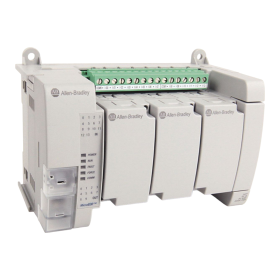
Page 14: Micro830 Controllers
Troubleshooting on page 263 for descriptions of status indicator operation for troubleshooting purposes. Micro830 Controllers Micro830 10/16-point controllers and status indicators Status indicator Controller Micro830 24-point controllers and status indicators Controller Status indicator Rockwell Automation Publication 2080-UM002L-EN-E - November 2021... -
Page 15: Micro850 Controllers
Serial communications status Run status Output status Fault status (1) For detailed description of the different status LED indicators, see Troubleshooting on page 263. Micro850 Controllers Micro850 24-point controllers and status indicators Status indicators Rockwell Automation Publication 2080-UM002L-EN-E - November 2021... - Page 16 40-pin high-speed plug-in connector RS-232/RS-485 non-isolated combo serial port RJ-45 EtherNet/IP connector Removable I/O terminal block (with embedded yellow and green LED indicators) Right-side cover Optional AC power supply Mounting screw hole / mounting foot Rockwell Automation Publication 2080-UM002L-EN-E - November 2021...
-
Page 17: Micro870 Controllers
RJ-45 Ethernet connector (with embedded green and Removable I/O terminal block yellow LED indicators) Right-side cover Optional power supply Mounting screw hole / mounting foot Status Indicator Description Description Description Input status Fault status Module Status Force status Rockwell Automation Publication 2080-UM002L-EN-E - November 2021... - Page 18 – 2080-LC50-24QWB – – – – 2080-LC50-24QVB – – – 2080-LC50-24QBB – – – 2080-LC50-48AWB – – – – – 2080-LC50-48QWB – – – – 2080-LC50-48QVB – – – 2080-LC50-48QBB – – – Rockwell Automation Publication 2080-UM002L-EN-E - November 2021...
-
Page 19: Programming Cables
For Micro850 and Micro870 controllers, a 10/100 Base-T Port (with embedded green and yellow LED indicators) is available for connection to an Ethernet network through any standard RJ-45 Ethernet cable. The LED indicators serve as indicators for transmit and receive status. Rockwell Automation Publication 2080-UM002L-EN-E - November 2021... - Page 20 Ethernet Status Indication Micro850 and Micro870 controllers also support two LEDs for EtherNet/IP™ to indicate the following: • Module status • Network status Troubleshooting on page 263 for descriptions of Module and Network status indicators. Rockwell Automation Publication 2080-UM002L-EN-E - November 2021...
-
Page 21: About Your Controller
Connected Components Workbench software is a set of collaborative tools Micro800 Controllers supporting Micro800 controllers. It is based on Rockwell Automation and Microsoft® Visual Studio® technology and offers controller programming, device configuration and integration with HMI editor. Use this software to program your controllers, configure your devices and design your operator interface applications. - Page 22 A new global variable __SYSVA_PROJ_INCOMPLETE has been added to indicate when Run Mode Changes are being made. This can be used to notify personnel on the HMI that there are uncommitted changes in the controller. Rockwell Automation Publication 2080-UM002L-EN-E - November 2021...
-
Page 23: Uncommitted Changes
If you have a project that was developed before version 8, you may need to reduce the default “Allocated” 8 KB Temporary Variables section from the Memory page in order to compile the project successfully. Rockwell Automation Publication 2080-UM002L-EN-E - November 2021... - Page 24 RMC memory as shown below, the operation will fail and a “not enough memory” error message will appear. Do not use RMC if you are near the limits of your controller memory. Rockwell Automation Publication 2080-UM002L-EN-E - November 2021...
-
Page 25: Limitations Of Rmc
WARNING: If you delete the output rung when in Run Mode Change and accept the changes, the output on the controller will remain ON. Use Run Mode Change on page 242 for an example on how to use this feature. Rockwell Automation Publication 2080-UM002L-EN-E - November 2021... -
Page 26: Using Run Mode Configuration Change (Rmcc)
For Micro830/Micro850/Micro870 controllers, the address configuration change is permanent and will retained when the controller is power cycled. From firmware revision 10 onwards, Micro820 controllers also retain the address configuration when the controller is power cycled. Rockwell Automation Publication 2080-UM002L-EN-E - November 2021... -
Page 27: Using Modbus Rtu Communication
You can verify that the node address has changed after performing RMCC by looking at the Communication Diagnostics tab for the controller. Rockwell Automation Publication 2080-UM002L-EN-E - November 2021... -
Page 28: Using Ethernet/Ip Communication
100 ms for one program scan. CIP Generic Message Parameters for RMCC using EtherNet/IP Parameter Value Service Class Instance Attribute ReqData IP address, Subnet mask, Gateway address ReqLen 22 bytes RMCC EtherNet/IP Example – Set the Parameters Rockwell Automation Publication 2080-UM002L-EN-E - November 2021... - Page 29 IP address change in order for duplicate address detection to work properly. You can verify that the IP address has changed after performing RMCC by looking at the Ethernet settings for the controller. Rockwell Automation Publication 2080-UM002L-EN-E - November 2021...
-
Page 30: Safety Considerations
Never alter these circuits to defeat their function. Serious injury or machine damage could result. WARNING: Explosion Hazard Do not connect or disconnect connectors while circuit is live. Rockwell Automation Publication 2080-UM002L-EN-E - November 2021... -
Page 31: Power Distribution
• The power-up sequence of devices in a system. • The amount of the power source voltage sag if the inrush current cannot be supplied. Rockwell Automation Publication 2080-UM002L-EN-E - November 2021... -
Page 32: Loss Of Power Source
Harmful contaminants or dirt could cause improper operation or damage to components. In extreme cases, you may need to use air conditioning to protect against heat build-up within the enclosure. Rockwell Automation Publication 2080-UM002L-EN-E - November 2021... -
Page 33: Master Control Relay
• Install emergency-stop switches and the master control relay in your system. Make certain that relay contacts have a sufficient rating for your application. Emergency-stop switches must be easy to reach. Rockwell Automation Publication 2080-UM002L-EN-E - November 2021... - Page 34 I/O circuits DC power supply. Use IEC 950/EN 60950 24V DC (Lo) (Hi) I/O circuits Line terminals: Connect to terminals of power supply. Line terminals: Connect to 24V DC terminals of power supply. Rockwell Automation Publication 2080-UM002L-EN-E - November 2021...
- Page 35 DC power supply. Use NEC Class 2 for UL Listing. (Lo) (Hi) 24 V DC I/O circuits Line terminals: Connect to terminals of power supply Line terminals: Connect to 24V DC terminals of power supply. Rockwell Automation Publication 2080-UM002L-EN-E - November 2021...
- Page 36 Chapter 2 About Your Controller Notes: Rockwell Automation Publication 2080-UM002L-EN-E - November 2021...
-
Page 37: Install Your Controller
Micro830 10-point and 16-point Controllers 2080-LC30-10QWB, 2080-LC30-10QVB, 2080-LC30-16AWB, 2080-LC30-16QWB, 2080-LC30-16QVB 100 (3.94) 80 (3.15) 90 (3.54) Measurements in mm (in.) Micro830 24-point Controllers 2080-LC30-24QWB, 2080-LC30-24QVB, 2080-LC30-24QBB 80 (3.15) 150 (5.91) 90 (3.54) Measurements in mm (in.) Rockwell Automation Publication 2080-UM002L-EN-E - November 2021... - Page 38 If optional accessories/modules are attached to the controller, such as the power supply 2080-PS120-240VAC or expansion I/O modules, make sure that there is 50.8 mm (2 in.) of space on all sides after attaching the optional parts. Rockwell Automation Publication 2080-UM002L-EN-E - November 2021...
-
Page 39: Din Rail Mounting
Leave the protective debris strip in place until you are finished wiring the controller and any other devices. For instructions on how to install your Micro800 system with expansion I/O, IMPORTANT see Micro800 Expansion I/O Modules User Manual, publication 2080-UM003. Rockwell Automation Publication 2080-UM002L-EN-E - November 2021... -
Page 40: Panel Mounting Dimensions
Chapter 3 Install Your Controller Panel Mounting Dimensions Micro830 10-Point and 16-Point Controllers 2080-LC30-10QWB, 2080-LC30-10QVB, 2080-LC30-16AWB, 2080-LC30-16QWB, 2080-LC30-16QVB 86 mm (3.39 in.) Micro830 24-Point Controllers 2080-LC30-24QWB, 2080-LC30-24QVB, 2080-LC30-24QBB 131 mm (5.16 in.) Rockwell Automation Publication 2080-UM002L-EN-E - November 2021... - Page 41 Micro850 24-Point Controllers 2080-LC50-24AWB, 2080-LC50-24QBB, 2080-LC50-24QVB, 2080-LC50-24QWB Micro870 24-Point Controllers 2080-LC70-24AWB, 2080-LC70-24QWB, 2080-LC70-24QWBK, 2080-LC70- 24QBB, 2080-LC70-24QBBK 131 mm (5.16 in.) Micro830 48-Point Controllers 2080-LC30-48AWB, 2080-LC30-48QWB, 2080-LC30-48QVB, 2080-LC30-48QBB 108 mm (4.25 in) 108 mm (4.25 in) 100 mm (3.9 in) Rockwell Automation Publication 2080-UM002L-EN-E - November 2021...
-
Page 42: System Assembly
Micro830, Micro850, and Micro870 24-point Controllers (Side) 87 (3.42) 80 (3.15) Micro830/Micro850/Micro870 24-pt controller with Micro800 power supply Expansion I/O Slots (Applicable to Micro850 and Micro870 only) Single-width (1st slot) Double-width (2nd slot) Measurements in mm (in.) 2085-ECR (terminator) Rockwell Automation Publication 2080-UM002L-EN-E - November 2021... - Page 43 Micro830 and Micro850 48-point Controllers (Side) (3.42) 80 (3.15) Micro830/Micro850 48-pt controller with Micro800 power supply Expansion I/O Slots (Applicable to Micro850 only) Single-width (1st slot) Measurements in mm (in.) Double-width (2nd slot) 2085-ECR (terminator) Rockwell Automation Publication 2080-UM002L-EN-E - November 2021...
- Page 44 Chapter 3 Install Your Controller Notes: Rockwell Automation Publication 2080-UM002L-EN-E - November 2021...
-
Page 45: Wiring Requirements And Recommendation
Where paths must cross, their intersection should be perpendicular. Do not run signal or communications wiring and power wiring in the same conduit. Wires with different signal characteristics should be routed by separate paths. Rockwell Automation Publication 2080-UM002L-EN-E - November 2021... -
Page 46: Use Surge Suppressors
A 1N4004 diode is acceptable for most applications. A surge suppressor can also be used. See Recommended Surge Suppressors on page These surge suppression circuits connect directly across the load device. Rockwell Automation Publication 2080-UM002L-EN-E - November 2021... -
Page 47: Recommended Surge Suppressors
24…48V AC 100-KFSC50 110…280V AC 100-KFSC280 380…480V AC 100-KFSC480 Bulletin 100/104K 700K 12…55 V AC, 12…77V DC 100-KFSV55 56…136 VAC, 78…180V DC 100-KFSV136 137…277V AC, 181…250 V DC 100-KFSV277 12…250V DC 100-KFSD250 Diode Rockwell Automation Publication 2080-UM002L-EN-E - November 2021... -
Page 48: Grounding The Controller
WARNING: All devices connected to the RS-232/RS-485 communication port must be referenced to controller ground, or be floating (not referenced to a potential other than ground). Failure to follow this procedure may result in property damage or personal injury. Rockwell Automation Publication 2080-UM002L-EN-E - November 2021... -
Page 49: Wiring Diagrams
2080-LC30-16AWB has no high-speed inputs. 2080-LC30-16QVB Input terminal block COM0 I-01 I-03 I-04 I-06 I-08 I-00 I-02 COM1 I-05 I-07 I-09 Output terminal block +DC24 +CM0 O-01 +CM1 O-03 O-04 -DC24 O-00 -CM0 O-02 -CM1 O-05 Rockwell Automation Publication 2080-UM002L-EN-E - November 2021... - Page 50 1601-XLP60EQ power supply instead of a 2080-PS120-240VAC power supply. Make sure to wire both the Micro870 controller and 2085-EP24VDC expansion power supply to the same 1601- XLP60EQ power supply. Rockwell Automation Publication 2080-UM002L-EN-E - November 2021...
- Page 51 I-06 COM1 I-09 I-11 I-13 +DC24 +CM0 O-01 +CM1 O-03 O-05 O-07 O-09 +24 VDC -DC24 O-00 -CM0 O-02 O-04 O-06 O-08 -CM1 -24 VDC +DC d +DC e -DC d -DC e Rockwell Automation Publication 2080-UM002L-EN-E - November 2021...
- Page 52 +DC24 -DC24 O-00 O-01 O-02 O-03 O-04 O-05 O-06 TERMINAL BLOCK 2 O-08 O-10 O-13 O-15 O-16 O-18 O-07 O-09 O-11 O-12 O-14 O-17 O-19 TERMINAL BLOCK 4 2080-LC30-48AWB has no high-speed inputs. Rockwell Automation Publication 2080-UM002L-EN-E - November 2021...
-
Page 53: Controller I/O Wiring
To ensure optimum accuracy for voltage type inputs, limit overall cable impedance by keeping all analog cables as short as possible. Locate the I/ O system as close to your voltage type sensors or actuators as possible. Rockwell Automation Publication 2080-UM002L-EN-E - November 2021... -
Page 54: Minimize Electrical Noise On Analog Channels
Do not ground the drain wire and foil shield at both ends of the cable. Wiring Examples Examples of sink/source, input/output wiring are shown below. Sink output wiring example User side Fuse +V DC Logic side Load – 24V supply DC COM Micro800 Sink output Rockwell Automation Publication 2080-UM002L-EN-E - November 2021... -
Page 55: Embedded Serial Port Wiring
8-pin Mini DIN connector. For example, the 1761-CBL-PM02 cable is typically used to connect the embedded serial port to PanelView™ Component HMI using RS-232. Rockwell Automation Publication 2080-UM002L-EN-E - November 2021... - Page 56 GND pin of the serial port is the DC common for the Serial Port Communication signals and is not intended for Shield Ground. • If the length of the serial cable is more than 3 meters, use an isolated serial port, catalog number 2080-SERIALISOL. Rockwell Automation Publication 2080-UM002L-EN-E - November 2021...
-
Page 57: Communication Connections
Modbus RTU Master and Slave • CIP Serial Client/Server (RS-232 only) • CIP Symbolic Client/Server • ASCII These are the communication protocols supported by Micro850 and Micro870 controllers only: • EtherNet/IP Client/Server • Modbus TCP Client/Server Rockwell Automation Publication 2080-UM002L-EN-E - November 2021... -
Page 58: Modbus Rtu
Modbus RTU Master and Modbus RTU Slave protocol. For more information on configuring your Micro800 controller for Modbus protocol, see the Connected Components Workbench Online Help. For more information about the Modbus protocol, see Modbus Protocol Specifications available from https://www.modbus.org. Rockwell Automation Publication 2080-UM002L-EN-E - November 2021... -
Page 59: Cip Serial Client/Server - Rs-232 Only
No protocol configuration is required other than configuring the Modbus mapping table. For information on Modbus mapping, see Modbus Mapping for Micro800 on page 211. Use MSG_MODBUS2 instruction to send Modbus TCP message over Ethernet port. Rockwell Automation Publication 2080-UM002L-EN-E - November 2021... -
Page 60: Cip Symbolic Client/Server
Configure CIP Serial Driver on page To configure for EtherNet/IP, see Configure Ethernet Settings on page CIP Symbolic Addressing Users may access any global variables through CIP Symbolic addressing except for system and reserved variables. Rockwell Automation Publication 2080-UM002L-EN-E - November 2021... -
Page 61: Cip Client Messaging
Sockets protocol is used for Ethernet communications to devices that do not support Modbus TCP and EtherNet/IP. Sockets support client and server, and TCP and UDP. Typical applications include communicating to printers, barcode readers, and PCs. Rockwell Automation Publication 2080-UM002L-EN-E - November 2021... -
Page 62: Cip Communications Pass-Thru
For program download USB to DeviceNet DeviceNet PowerFlex® 525 drive with 25-COMM-D adapter (Address 1) Micro850 controller with For program download 2080-DNET20 plug-in scanner (Address 0) CompactBlock™ LDX I/O (Address 2) Rockwell Automation Publication 2080-UM002L-EN-E - November 2021... -
Page 63: Use Modems With Micro800 Controllers
(50 ft) with a 25-pin or 9-pin connector. See the following typical pinout for constructing a straight-through cable: DTE Device (Micro830/850/870 DCE Device Channel 0) (Modem, etc) ) + ( ) - ( Rockwell Automation Publication 2080-UM002L-EN-E - November 2021... -
Page 64: Configure Serial Port
Configure all devices in the system for the same communication rate. Default baud rate is set at 38,400 bps. 4. In most cases, parity and station address should be left at default settings. Rockwell Automation Publication 2080-UM002L-EN-E - November 2021... -
Page 65: Configure Modbus Rtu
Specifies the amount of time after a packet is transmitted that an ACK Timeout (x20 ms) ACK is expected. Configure Modbus RTU 1. Open your Connected Components Workbench project. On the device configuration tree, go to the Controller properties. Click Serial Port. Rockwell Automation Publication 2080-UM002L-EN-E - November 2021... - Page 66 RS-232, RS-232 RTS/CTS, RS-485 RS-232 Data bits Always 8 Stop bits 1, 2 Response timer 0…999,999,999 milliseconds Broadcast Pause 0…999,999,999 milliseconds Inter-char timeout 0…999,999,999 microseconds RTS Pre-delay 0…999,999,999 microseconds RTS Post-delay 0…999,999,999 microseconds Rockwell Automation Publication 2080-UM002L-EN-E - November 2021...
-
Page 67: Configure Ascii
ASCII Advanced Parameters Parameters Options Default Full Duplex Half-duplex with continuous carrier Control Line No Handshake Half-duplex without continuous carrier No Handshake Deletion Mode Ignore Ignore Printer Data bits 7, 8 Stop bits 1, 2 Rockwell Automation Publication 2080-UM002L-EN-E - November 2021... -
Page 68: Configure Ethernet Settings
ARP. When the DHCP server is again able to service requests, the Micro800 controller updates its address automatically. 3. Click the checkbox Detect duplicate IP address to enable detection of duplicate address. 4. Under Ethernet, click Port Settings. Rockwell Automation Publication 2080-UM002L-EN-E - November 2021... -
Page 69: Validate Ip Address
MAC address, separated by a hyphen. For example: 2080LC50-xxxxxxxxxxxx, where xxxxxxxxxxxx is the MAC address. The user can change the host name using the CIP Service Set Attribute Single when the controller is in Program/Remote Program mode. Rockwell Automation Publication 2080-UM002L-EN-E - November 2021... -
Page 70: Configure Cip Serial Driver
7.011 onwards. This can be used in place of Modbus addressing. FactoryTalk® Linx software version 5.70 (CPR9 SR7) or later and FactoryTalk® Linx Gateway software version 3.70 (CPR9 SR7) or later are required. Rockwell Automation Publication 2080-UM002L-EN-E - November 2021... -
Page 71: Program Execution In Micro800
Alternatively, you can assign a program to an available interrupt and have it executed only when the interrupt is triggered. A program assigned to the User Fault Routine runs once just prior to the controller going into Fault mode. Rockwell Automation Publication 2080-UM002L-EN-E - November 2021... -
Page 72: Execution Rules
I/O or expansion I/O module. ATTENTION: If the optional module feature is enabled, use the MODULE_INFO instruction to verify that the module is present because the controller will not fault if the module is missing. Rockwell Automation Publication 2080-UM002L-EN-E - November 2021... -
Page 73: Controller Load And Performance Considerations
When transitioning from Program mode to Run mode, all analog output variables hold their last state but all digital output variables are cleared. Two system variables are also available from revision 2 and later. Rockwell Automation Publication 2080-UM002L-EN-E - November 2021... -
Page 74: Variable Retention
This means that program size can exceed the published specifications if data size is sacrificed and vice versa. This flexibility allows maximum usage of execution memory. In addition to the Rockwell Automation Publication 2080-UM002L-EN-E - November 2021... -
Page 75: Guidelines And Limitations For Advanced Users
Memory Usage (Data) : 3456 bytes • You may encounter an Insufficient Reserved Memory error while downloading and compiling a program over a certain size. One workaround is to use arrays, especially if there are many variables. Rockwell Automation Publication 2080-UM002L-EN-E - November 2021... - Page 76 Chapter 6 Program Execution in Micro800 Notes: Rockwell Automation Publication 2080-UM002L-EN-E - November 2021...
-
Page 77: Pto Motion Control
2080-LC30-10QVB 2080-LC30-16QVB 24 Points 2080-LC30-24QVB 2080-LC30-24QBB 2080-LC50-24QVB 2080-LC50-24QBB 2080-LC70-24QBB 2080-LC70-24QBBK 48 Points 2080-LC30-48QVB 2080-LC30-48QBB 2080-LC50-48QVB 2080-LC50-48QBB (1) For Micro830 catalogs, Pulse Train Output functionality is only supported from firmware revision 2 and later. Rockwell Automation Publication 2080-UM002L-EN-E - November 2021... -
Page 78: Use The Micro800 Motion Control Feature
Jerk Inputs on page may induce vibrations. To use the Micro800 motion feature, you need to: 1. Configure the Axis Properties Motion Axis Configuration in Connected Components Workbench on page 101 for instructions. Rockwell Automation Publication 2080-UM002L-EN-E - November 2021... -
Page 79: Input And Output Signals
These I/O can be configured through the axis configuration feature in Connected Components Workbench. Any outputs assigned for motion should not be controlled in the user program. Motion Axis Configuration in Connected Components Workbench on page 101. Rockwell Automation Publication 2080-UM002L-EN-E - November 2021... - Page 80 5 seconds when the last PTO pulse sent out. This signal is the zero pulse signal from the motor Home Marker INPUT encoder. This signal can be used for fine homing Not Shared sequence to improve the homing accuracy. Rockwell Automation Publication 2080-UM002L-EN-E - November 2021...
- Page 81 2. To help you configure Kinetix3 drive parameters, so the drive can communicate and be controlled by a Micro830/Micro850/Micro870 controller, see publication CC-QS033. The parameter Command Type must be set to “Step/Direction.Positive Logic”, and the parameter Controller Output Type must be set to “Open Collector Input”. Rockwell Automation Publication 2080-UM002L-EN-E - November 2021...
-
Page 82: Motion Control Function Blocks
The axis remains in the state “Stopping” as long as Execute is still TRUE or velocity zero is not yet reached. As soon as “Done” is SET and “Execute” is FALSE the axis goes to state “StandStill”. Rockwell Automation Publication 2080-UM002L-EN-E - November 2021... -
Page 83: General Rules For The Motion Control Function Blocks
• If the motion engine fails to generate the motion profile prescribed by the dynamic input parameters, the function block reports an error (Error ID: MC_FB_ERR_PROFILE). Function Block and Axis Status Error Codes on page 98 for more information about error codes. Rockwell Automation Publication 2080-UM002L-EN-E - November 2021... - Page 84 (for example, MC_POWER to MC_HOME). Axis output When used in a Ladder Diagram, you cannot assign a variable to the Axis output parameter of another motion function block because it is read-only. Rockwell Automation Publication 2080-UM002L-EN-E - November 2021...
- Page 85 Busy output will stay true forever even though the function block has finished executing. Behavior of Busy Output Output Active In current implementation, buffered moves are not supported. Consequently, Busy and Active outputs have the same behavior. Rockwell Automation Publication 2080-UM002L-EN-E - November 2021...
- Page 86 MC_MoveRelative, MC_MoveAbsolute will be busy until final position is reached. MC_MoveVelocity, MC_Halt, and MC_Stop will be busy until final velocity is reached. Rockwell Automation Publication 2080-UM002L-EN-E - November 2021...
- Page 87 Execute input is toggled again. If Execute is toggled again before Busy is false, the new command is ignored. No error is generated. Time Execute1 Busy1 Rockwell Automation Publication 2080-UM002L-EN-E - November 2021...
- Page 88 Busy during acceleration (or deceleration). Only a single instance of the function block is required. To bring the axis to a standstill, use MC_Halt. Time Execute1 Busy Halt Execute Busy Rockwell Automation Publication 2080-UM002L-EN-E - November 2021...
- Page 89 If MC_Halt aborts another movement function block during acceleration and the MC_Halt Jerk input parameter is less than the Jerk of the currently executing FB, the Jerk of the currently executing function block is used to prevent excessively long deceleration. Rockwell Automation Publication 2080-UM002L-EN-E - November 2021...
-
Page 90: Motion Axis And Parameters
The axis is always in one of the defined states see Figure 6 on page 91. Any motion command is a transition that changes the state of the axis and, as a consequence, modifies the way the current motion is computed. Rockwell Automation Publication 2080-UM002L-EN-E - November 2021... -
Page 91: Axis States
Axis state can be monitored through the Axis Monitor feature of the Connected Components Workbench software when in debug mode. Motion States State Value State Name 0x00 Disabled 0x01 Standstill 0x02 Discrete Motion 0x03 Continuous Motion 0x04 Homing 0x06 Stopping 0x07 Stop Error Rockwell Automation Publication 2080-UM002L-EN-E - November 2021... -
Page 92: Limits
Soft Limits • PTO Pulse Limits Motion Axis Configuration in Connected Components Workbench on page 101 for information on how to configure limits and stop profiles and the acceptable value range for each. Rockwell Automation Publication 2080-UM002L-EN-E - November 2021... - Page 93 Soft limits are displayed in user-defined units. The user can enable individual soft limits. For non-enabled soft limits (whether upper or lower), an infinite value is assumed. Rockwell Automation Publication 2080-UM002L-EN-E - November 2021...
-
Page 94: Motion Stop
For a continuous motion, if the axis is homed, and the soft limit in the motion direction is enabled, soft limit will be detected before PTO pulse limit being detected. Motion Stop There are three types of stops that can be configured for an axis. Rockwell Automation Publication 2080-UM002L-EN-E - November 2021... - Page 95 The Emergency Stop is configured as Decelerating Stop. During motion, the MC_Stop function block is issued with deceleration parameter set to 0. • During motion, MC_Stop function block is issued with Deceleration parameter not set to 0. Rockwell Automation Publication 2080-UM002L-EN-E - November 2021...
-
Page 96: Motion Direction
AccFlag UINT8 Indicates whether the axis is in an accelerating movement or not. DecFlag UINT8 Indicates whether the axis is in a decelerating movement or not. Rockwell Automation Publication 2080-UM002L-EN-E - November 2021... -
Page 97: Axis Error Scenarios
Stopping or Error Stopping sequence. For the above exceptions, it is still possible for the user application to issue a successful movement function block to the axis after the axis state changes. Rockwell Automation Publication 2080-UM002L-EN-E - November 2021... -
Page 98: Mc_Engine_Diag Data Type
Table 7 on page Error code 128 is warning information to indicate the motion profile has been changed and velocity has been adjusted to a lower value but the function block can execute successfully. Rockwell Automation Publication 2080-UM002L-EN-E - November 2021... - Page 99 Correct the motion profile in the function block, or re- the axis velocity is compatible with the requested motion execute the function block when the axis velocity is profile. compatible with the requested motion profile. Rockwell Automation Publication 2080-UM002L-EN-E - November 2021...
-
Page 100: Major Fault Handling
Execute homing against the axis using MC_Home Function Block. Block. Motion internal Fault, Error ID = 0x80. Warning: The requested motion parameter for the axis has Contact your local Rockwell Automation technical support MC_FB_PARAM_MODIFIED been adjusted. representative. For contact information, see: rok.auto/ The function block executes successfully. -
Page 101: Motion Axis Configuration In Connected Components Workbench
When an axis is added to the configuration, the Motion Engine Execution Time can be configured from 1…10 ms (default: 1 ms). This global parameter applies to all motion axis configurations. 1. On the Device Configuration tree, right-click <New Axis>. Click Add. Rockwell Automation Publication 2080-UM002L-EN-E - November 2021... -
Page 102: Edit Axis Configuration
To edit these general parameters, see Input and Output Signals on page 79 IMPORTANT for more information about fixed and configurable outputs. Rockwell Automation Publication 2080-UM002L-EN-E - November 2021... - Page 103 Edit the Motor Load properties as defined in Table 10 on page 104. IMPORTANT Certain parameters for Motor and Load are Real values. For more information, see Real Data Resolution on page 108 Rockwell Automation Publication 2080-UM002L-EN-E - November 2021...
- Page 104 ATTENTION: Modifying Motor Revolution parameters may cause axis runaway. Limits Edit the Limits parameters based on the table below. ATTENTION: To learn more about the different types of Limits, see Limits on page Rockwell Automation Publication 2080-UM002L-EN-E - November 2021...
- Page 105 Supply the valid value. 3. Click Dynamics. The <Axis Name> - Dynamics tab appears. Edit the Dynamics parameters based on the values in Table 12 on page 106. Rockwell Automation Publication 2080-UM002L-EN-E - November 2021...
- Page 106 A red border on an input field indicates that an invalid value has been entered. Scroll over the field to see tooltip message that will let you know the valid value range for the parameter. Supply the valid value. Rockwell Automation Publication 2080-UM002L-EN-E - November 2021...
-
Page 107: Axis Start/Stop Velocity
• When the target velocity is smaller than Start/Stop velocity, move the axis immediately at the target velocity. Rockwell Automation Publication 2080-UM002L-EN-E - November 2021... -
Page 108: Real Data Resolution
A tooltip message should let you know the expected range of values for the parameter. The range of values presented in the tooltip messages are also presented in REAL data format. Rockwell Automation Publication 2080-UM002L-EN-E - November 2021... - Page 109 Axis Monitor Example The Axis Monitor displays seven significant digits with rounding. ATTENTION: See Motion Axis Configuration in Connected Components Workbench on page 101 to learn more about the different axis configuration parameters. Rockwell Automation Publication 2080-UM002L-EN-E - November 2021...
-
Page 110: Pto Pulse Accuracy
Homing jerk should not be greater than maximum jerk. • Homing creep velocity should not be greater than maximum velocity. Delete an Axis 1. On the device configuration tree, and under Motion, right-click the axis name and select Delete. Rockwell Automation Publication 2080-UM002L-EN-E - November 2021... -
Page 111: Monitor An Axis
On most scenarios, the MC_Home function block needs to be executed to calibrate the axis position against the axis home configured after MC_Power (On) is done. Table 16 on page 112 describes five homing modes supported on Micro830, Micro850, and Micro870 controllers. Rockwell Automation Publication 2080-UM002L-EN-E - November 2021... -
Page 112: Conditions For Successful Homing
2. The Lower limit switch is configured as enabled and wired; The different homing modes, as defined in Table 16, can have different, but still similar motion sequence. The concept discussed below is applicable to various homing configurations. Rockwell Automation Publication 2080-UM002L-EN-E - November 2021... -
Page 113: Mc_Home_Abs_Switch
3. Move to the configured home position. The mechanical home position recorded during moving right sequence, plus the home offset configured for the axis in the Connected Components Workbench software. Rockwell Automation Publication 2080-UM002L-EN-E - November 2021... -
Page 114: Mc_Home_Limit_Switch
In this case, the homing motion fails and moves continuously to the left until drive or moving part fails to move. User needs to make sure the moving part is at the proper location before homing starts. Rockwell Automation Publication 2080-UM002L-EN-E - November 2021... -
Page 115: Mc_Home_Ref_With_Abs
Scenario 3: Moving part on Lower Limit or Home switch before homing starts The homing motion sequence for this scenario is as follows: 1. Moving part moves to its right side (in positive direction) in creep velocity to detect Home switch On→Off edge; Rockwell Automation Publication 2080-UM002L-EN-E - November 2021... -
Page 116: Mc_Home_Ref_Pulse
Scenario 2: Moving part on Lower Limit switch before homing starts The homing motion sequence for this scenario is as follows: 1. Moving part moves to its right side (in Positive direction) in creep velocity to detect Lower Limit switch On→Off edge; Rockwell Automation Publication 2080-UM002L-EN-E - November 2021... -
Page 117: Mc_Home_Direct
Enable/power up the PWM axis immediately after going to RUN mode. PWM axis will remain powered ON (until Program mode, and so on). MC_Power_1 __SYSVA_FIRST_SCAN MC_Power Axis PWM0 Axis TRUE Status Enable Enable_Positive Busy TRUE Active Enable_Negative TRUE Error ErrorID Rockwell Automation Publication 2080-UM002L-EN-E - November 2021... - Page 118 After first scan, use MC_MoveVelocity to continually set the PWM frequency (for example: 50,000 => 50 KHz) from global variable G_PWM_Frequency. PWM axis will run forever (until Program Mode, MC_Halt, and so on). MC_MoveVelocity_1 __SYSVA_FIRST_SCAN MC_MoveVelocity PWM0 Axis AxisIn InVelocity TRUE Execut Busy G_PWM_Frequency Velocity Active 50000.0 Acceleration Direction 50000.0 Acceleration CommandAborted Deceleration Error Jerk ErrorID DirectionIn Rockwell Automation Publication 2080-UM002L-EN-E - November 2021...
-
Page 119: Pou Pwm_Program
If the feedback axis is in the error state because the configured position limits have been exceeded, using the MC_Reset function block to reset the axis may not clear the error as there may still be pulse detected from the encoder. Rockwell Automation Publication 2080-UM002L-EN-E - November 2021... - Page 120 Chapter 7 Motion Control Notes: Rockwell Automation Publication 2080-UM002L-EN-E - November 2021...
-
Page 121: Use The High-Speed Counter And Programmable Limit Switch
What is High-Speed Counter? High-Speed Counter is used to detect narrow (fast) pulses, and its specialized instructions to initiate other control operations based on counts reaching preset values. These control operations include the automatic and immediate Rockwell Automation Publication 2080-UM002L-EN-E - November 2021... -
Page 122: Features And Operation
UFSetting before triggering Start/Run HSC. Otherwise, the controller will be faulted. (Setting a value for LPSetting is optional for certain counting modes.) To learn more about HscAppData variable input, see HSC APP Data Structure on page 125. Rockwell Automation Publication 2080-UM002L-EN-E - November 2021... -
Page 123: Hsc Inputs And Wiring Mapping
HSC5. Each set of counters share the input. The following table shows the dedicated inputs for the HSCs depending on the mode. Table 18 - HSC Input Wiring Mapping Embedded Input HSC0 Reset Hold HSC1 HSC2 Reset Hold Rockwell Automation Publication 2080-UM002L-EN-E - November 2021... - Page 124 Count Up Count Down Not Used Two Input Counter with External Count Up Count Down Reset Hold Reset and Hold (mode 3b) Quadrature Counter (mode 4a) A Type input B Type input Not Used Rockwell Automation Publication 2080-UM002L-EN-E - November 2021...
-
Page 125: High Speed Counter (Hsc) Data Structures
To reload HSC configuration, change the HSC APP Data, then call HSC function block with command 0x03 (set/reload). Otherwise, the change to HSC App Data during HSC counting is ignored. Rockwell Automation Publication 2080-UM002L-EN-E - November 2021... - Page 126 0x01: Expansion (not yet implemented) 0x02: Plug-in module Module Slot ID: 0x00: Embedded 12…8 0x01…0x1F: Expansion (not yet implemented) 0x01…0x05: Plug-in module Module internal HSC ID: 0x00-0x0F: Embedded 7…0 0x00-0x07: Expansion (not yet implemented) 0x00-0x07: Plug-in module Rockwell Automation Publication 2080-UM002L-EN-E - November 2021...
- Page 127 Embedded Input 1 Embedded Input 2 Embedded Input 3 CE Bit Comments Function Count Not Used Reset Hold Example 1 on (1) off (0) off (0) on (1) HSC Accumulator + 1 count Rockwell Automation Publication 2080-UM002L-EN-E - November 2021...
- Page 128 Hold accumulator value Blank cells = don’t care, = rising edge, = falling edge Inputs 0 through 11 are available for use as inputs to other functions regardless of the HSC being used. Rockwell Automation Publication 2080-UM002L-EN-E - November 2021...
- Page 129 Embedded Input 1 Embedded Input 2 Embedded Input 3 CE Bit Comments Function Count A Count B Not Used Not Used off (0) on (1) HSC Accumulator + 1 count Example 1 Rockwell Automation Publication 2080-UM002L-EN-E - November 2021...
- Page 130 Count Down Acc. Value TRUE Count Up Acc. Value TRUE Count Up Acc. Value TRUE Count Down Acc. Value OFF or ON OFF or ON Hold Acc. Value FALSE Hold Acc. Value Rockwell Automation Publication 2080-UM002L-EN-E - November 2021...
- Page 131 0 and 1 or an HSC error is generated. 2. Greater than or equal to the data resident in the underflow (HSCAPP.UFSetting) parameter for all HSC Mode (HSCAPP.HSCMode) or an HSC error is generated. Rockwell Automation Publication 2080-UM002L-EN-E - November 2021...
- Page 132 HSC and which outputs are not controlled by the HSC. For example, if the user wants to control outputs 0, 1, 3, using HSC then the user needs to assign, HscAppData.OutputMask = 2#1011 (OR using Decimal Value: HscAppData.OutputMask = 11) Rockwell Automation Publication 2080-UM002L-EN-E - November 2021...
- Page 133 132. The high output bit pattern can be configured during initial setup, or while the controller is operating. Use the HSC function block to load the new parameters while the controller is operating. Rockwell Automation Publication 2080-UM002L-EN-E - November 2021...
-
Page 134: Hsc Sts (Hsc Status) Data Structure
HSC sub-system. The most common type of error that this bit represents is a configuration error. When this bit is set (1), you should look at the specific error code in parameter HSCSTS.ErrorCode. Rockwell Automation Publication 2080-UM002L-EN-E - November 2021... - Page 135 (1) For Mode descriptions, see HSC Mode (HSCAPP.HSCMode) on page 127. The Underflow status flag is set (1) by the HSC sub-system whenever the accumulated value (HSCSTS.Accumulator) has counted through the underflow variable (HSCAPP.UFSetting). Rockwell Automation Publication 2080-UM002L-EN-E - November 2021...
- Page 136 HSC Mode (HSCAPP.HSCMode) on page 127. The Overflow Interrupt status bit is set (1) when the HSC accumulator counts through the overflow value and the HSC interrupt is triggered. This bit can be Rockwell Automation Publication 2080-UM002L-EN-E - November 2021...
- Page 137 HSC Mode (HSCAPP.HSCMode) on page 127. The Low Preset Interrupt status bit is set (1) when the HSC accumulator reaches the low preset value and the HSC interrupt has been triggered. This bit Rockwell Automation Publication 2080-UM002L-EN-E - November 2021...
- Page 138 If either mode 0 or mode 1 is configured, the accumulator is reset to 0 when a high preset is reached or when an overflow condition is detected. High Preset (HSCSTS.HP) Description Data Format User Program Access HSCSTS.HP long word (32-bit INT) read only Rockwell Automation Publication 2080-UM002L-EN-E - November 2021...
-
Page 139: High-Speed Counter (Hsc) Function Block
PLS data block. High-Speed Counter (HSC) The HSC function block can be used to start/stop HSC counting, to refresh Function Block HSC status, to reload HSC setting, and to reset HSC accumulator. Rockwell Automation Publication 2080-UM002L-EN-E - November 2021... -
Page 140: Hsc Commands (Hsccmd)
If the command is enabled continuously, it may cause errors. HSC AppData.Accumalator value is updated automatically by the HSC mechanism with the same value as the HSC Sts.Accumulator. To set one Rockwell Automation Publication 2080-UM002L-EN-E - November 2021... -
Page 141: Hsc_Set_Sts Function Block
Describes which HSC status to set. Mode1Done Input BOOL Mode 1A or 1B counting is done. High Preset reached. HPReached Input BOOL This bit can be reset to FALSE when HSC is not counting. Rockwell Automation Publication 2080-UM002L-EN-E - November 2021... -
Page 142: Programmable Limit Switch (Pls) Function
Low preset Output data The total number of elements for one PLS data cannot be larger than 255. When PLS is not enabled, PLS data are still required to be defined, but can be not initialized. Rockwell Automation Publication 2080-UM002L-EN-E - November 2021... -
Page 143: Pls Operation
The PLS function can operate with all of the other HSC capabilities. The ability to select which HSC events generate a user interrupt are not limited. Rockwell Automation Publication 2080-UM002L-EN-E - November 2021... -
Page 144: Pls Example
HSCAPP.OutputMask and energizes the outputs 0 and 1. This will repeat as the HSCSTS.Accumulator reaches 500, 750, and 1000. The controller energizes outputs 0...2, 0...3, and 0...4 respectively. Once completed, the cycle resets and repeats from HSCSTS.HP = 250. Rockwell Automation Publication 2080-UM002L-EN-E - November 2021... -
Page 145: Hsc Interrupts
In the User Interrupt configuration window, select HSC, and HSC ID, which is the interrupt triggering the User Interrupt. Figure 13 shows the selectable fields in the Interrupt configuration window. Figure 13 - Interrupt Configuration Window Rockwell Automation Publication 2080-UM002L-EN-E - November 2021... -
Page 146: Hsc Interrupt Pou
Preset Reached condition is detected by the HSC, the HSC user interrupt is not executed. This bit is controlled by the user program and retains its value through a power cycle. It is up to the user program to set and clear this bit. Rockwell Automation Publication 2080-UM002L-EN-E - November 2021... -
Page 147: Hsc Interrupt Status Information
This status bit can be monitored or used for logic purposes in the control program if you need to determine when a subroutine cannot be executed immediately. This bit is maintained by the controller and is set and cleared automatically. Rockwell Automation Publication 2080-UM002L-EN-E - November 2021... - Page 148 The controller can process 1 active and maintain up to 1 pending user interrupt conditions before it sets the lost bit. This bit is set by the controller. It is up to the control program to utilize, track the lost condition if necessary. Rockwell Automation Publication 2080-UM002L-EN-E - November 2021...
-
Page 149: Controller Security
2080-MEMBAK-RTC2 for Micro830, Micro850 and Micro870; 2080- MEMBAK-RTC for Micro830 and Micro850; 2080-LCD for Micro810; and microSD card for Micro820 controllers). For instructions on how to set, change, and clear controller passwords, see Configure Controller Password on page 227. Rockwell Automation Publication 2080-UM002L-EN-E - November 2021... -
Page 150: Compatibility
(firmware revision 2) and Connected Components Workbench software version 2. Upload from a Password-Protected Controller 1. Launch the Connected Components Workbench software. 2. In the Project Organizer, expand Catalog by clicking the + sign. 3. Select the target controller. Rockwell Automation Publication 2080-UM002L-EN-E - November 2021... -
Page 151: Debug A Password-Protected Controller
10 or later project, the password in the controller will be automatically converted to the new algorithm. If communication is lost during the download, repeat the download and IMPORTANT verify that the controller is password protected. Rockwell Automation Publication 2080-UM002L-EN-E - November 2021... -
Page 152: Transfer Controller Program And Password-Protect Receiving
You can flash update the controller using the Reset option to clear the password before restoring the project to the controller. Rockwell Automation Publication 2080-UM002L-EN-E - November 2021... -
Page 153: Configure Controller Password
To perform a project backup from a controller to the memory module, follow these steps: 1. Create a new program and choose the desired controller. The Micro850 controller is used for this example. Rockwell Automation Publication 2080-UM002L-EN-E - November 2021... - Page 154 3. Add the memory module to the first slot in the controller. 4. Click Configuration under the MEMBAK-RTC properties and select “Load Always” or “Load on Memory Error” for the Load on power up option. 5. Build and Download the project to the controller. Rockwell Automation Publication 2080-UM002L-EN-E - November 2021...
- Page 155 4. When the operation is finished you can unplug the module and leave the slot empty, or plug in a different MEMBAK-RTC module if you want to use the RTC functionality. Rockwell Automation Publication 2080-UM002L-EN-E - November 2021...
- Page 156 Chapter 9 Controller Security Notes: Rockwell Automation Publication 2080-UM002L-EN-E - November 2021...
-
Page 157: Using Microsd Cards
• The SD status LED will not blink when flash upgrading the firmware from the microSD card. • The SD status LED does not blink continuously for the entire duration of the restore operation. Rockwell Automation Publication 2080-UM002L-EN-E - November 2021... -
Page 158: Project Backup And Restore
The microSD card stores the controller password in encrypted format. When the password is mismatched, the contents of the microSD card is not restored on the controller. Backup and restore can be configured to trigger through the following ways: Rockwell Automation Publication 2080-UM002L-EN-E - November 2021... -
Page 159: Backup And Restore Directory Structure
ConfigMeFirst.txt file. The user needs to ensure that the directory is populated with correct contents before restoring. The ConfigMeFirst.txt file is a configuration file stored on the microSD card that the user can optionally create to customize backup, restore, recipe, and Rockwell Automation Publication 2080-UM002L-EN-E - November 2021... -
Page 160: Power-Up Settings In Configmefirst.txt
Power up and set IP address to xxx [IPA = xxx.xxx.xxx.xxx] Power-up (must be numbers only). Power up and set subnet mask to xxx [SNM = xxx.xxx.xxx.xxx] Power-up (must be numbers only). Rockwell Automation Publication 2080-UM002L-EN-E - November 2021... - Page 161 ConfigMeFirst.txt. • The [ESFD], [IPA], [SNM], and [GWA] settings overwrite the respective communication settings from project restore due to [RSD], Load Always or Load on Memory Error. Sample ConfigMeFirst.txt File Rockwell Automation Publication 2080-UM002L-EN-E - November 2021...
-
Page 162: General Configuration Rules In Configmefirst.txt
2. Insert a microSD card into the microSD card slot. 3. Set the controller to program mode. 4. Under the Memory Card option in your controller settings, click Backup to Memory Card. Rockwell Automation Publication 2080-UM002L-EN-E - November 2021... - Page 163 3. Use a compression program to zip these image files and send them to your customer through email. The customer must unzip these image files into the root directory of their microSD card and verify that the location is identical to the original (default is <Micro800>\USERPRJ). Rockwell Automation Publication 2080-UM002L-EN-E - November 2021...
-
Page 164: Data Log
Micro800 controller into the microSD card. You can retrieve the recorded datasets on the microSD card by reading the contents of the microSD card through a card reader or by doing an upload through the Connected Components Workbench software. Rockwell Automation Publication 2080-UM002L-EN-E - November 2021... - Page 165 Note that in cases where there are simultaneous RCP and DLG function block IMPORTANT execution or uploads/downloads/searches, the activities are queued up and handled one by one by the program scan. You will notice a slowdown in performance in these cases. Rockwell Automation Publication 2080-UM002L-EN-E - November 2021...
-
Page 166: Data Log Directory Structure
(1) Once the data log limits is reached (that is, 50 Grpxx folders per day, then an error (ErrorID 3: DLG_ERR_DATAFILE_ACCESS) is returned. Data Log Function (DLG) Block The data logging function block lets a user program to write run-time global values into the data logging file in microSD card. Rockwell Automation Publication 2080-UM002L-EN-E - November 2021... - Page 167 Data log configuration file format is wrong. DLG_ERR_RTC Real time clock is invalid. DLG_ERR_UNKNOWN Unspecified error has occurred. File access error will be returned during DLG function block execution when IMPORTANT card is full. Rockwell Automation Publication 2080-UM002L-EN-E - November 2021...
- Page 168 BOOL TRUE and FALSE 1: TRUE) SINT Signed 8-bit integer value -128, 127 Signed 16-bit integer value -32768, 32767 DINT Signed 32-bit integer value -2147483648, 2147483647 LINT Signed 64-bit integer value -9223372036854775808, 9223372036854775807 Rockwell Automation Publication 2080-UM002L-EN-E - November 2021...
-
Page 169: Recipe
(Rcp_Id01...Rcp_Id10) with a maximum number of 50 Maximum number of recipes recipe files in each directory. in each set Maximum number of variables Configured in Connected Components Workbench per recipe software. Maximum bytes per recipe file 4 KB Rockwell Automation Publication 2080-UM002L-EN-E - November 2021... -
Page 170: Recipe Directory Structure
Enable Status RWFlag ErrorID CfgId RcpName Rockwell Automation Publication 2080-UM002L-EN-E - November 2021... - Page 171 Recipe data file is absent. RCP_ERR_DATAFILE_FORMAT Recipe data file contents are wrong. RCP_ERR_DATAFILE_SIZE Recipe data file size is too big (>4K). File access error will be returned during RCP function block execution when IMPORTANT card is full. Rockwell Automation Publication 2080-UM002L-EN-E - November 2021...
-
Page 172: Quickstart Projects For Data Log And Recipe Function Blocks
The following sample quickstart projects provide step-by-step instructions on Log and Recipe Function how to use the Data Log and Recipe function blocks in the Connected Components Workbench software to generate and manage your recipe files Blocks and data logs. Rockwell Automation Publication 2080-UM002L-EN-E - November 2021... -
Page 173: Use The Data Log Feature
3. Click Add Variable to add variables to the dataset. You can add up to 128 variables to each dataset. For this quickstart sample project, add the following variables that you have previously created to Dataset 1. Local Variables Variable Name Data Type data_bool BOOL data_int8 data_string STRING Rockwell Automation Publication 2080-UM002L-EN-E - November 2021... - Page 174 4. From the Toolbox, double-click Block to add it to the rung. 5. On the Block Selector window that appears, type DLG to filter the DLG function block from the list of available function blocks. Click OK. Rockwell Automation Publication 2080-UM002L-EN-E - November 2021...
- Page 175 To do so, click the CfgID input box. From the Variable Selector window that appears, click the Defined Words tab and choose from the list of defined words. For example, DSET1 that corresponds to DSET1 in your recipe configuration. See Figure Rockwell Automation Publication 2080-UM002L-EN-E - November 2021...
- Page 176 After configuring data log properties, build the program and download to the controller. Execute DLG Function Block Execute the DLG function block. Notice the Status output go from 0 (Idle) to 1 (Enable), and 2 (Succeed). Rockwell Automation Publication 2080-UM002L-EN-E - November 2021...
- Page 177 For better data log file management, you can use a third-party tool or DOS CMD to merge all your data log files into a single file and import as a CSV file in Excel®. Rockwell Automation Publication 2080-UM002L-EN-E - November 2021...
-
Page 178: Use The Recipe Feature
3. Click Add Variable to add variables to the recipe. You can add up to 128 variables to each recipe. For this quickstart sample project, add the following variables that you have previously created to RCP 1: Local Variables Variable Name Data Type data_bool BOOL data_int8 Rockwell Automation Publication 2080-UM002L-EN-E - November 2021... - Page 179 2. Right-click Programs. Select Add New LD: Ladder Diagram. Name the Program (for example, Prog2). 3. From the Toolbox, double-click Direct Contact to add it to the first rung. 4. From the Toolbox, double-click Block to add it to the rung. Rockwell Automation Publication 2080-UM002L-EN-E - November 2021...
- Page 180 8. Create the following local variables for your program, in addition to the ones that you have already created for data log. Local Variables Variable Name Data Type recipe_file STRING recipe_file2 STRING cfg_id2 USINT read BOOL write BOOL Rockwell Automation Publication 2080-UM002L-EN-E - November 2021...
- Page 181 Defined Words tab and choose from the list of defined words. For example, RCP1 that corresponds to RCP1 in your recipe configuration. See Figure Figure 19 - Choose a Predefined Variable Rockwell Automation Publication 2080-UM002L-EN-E - November 2021...
- Page 182 2. Select Recipe. Click Manage and then choose Upload. Through Manage, you can also choose to Download and Delete recipe files. 3. From the Upload window that appears, select the batch of recipe files that you would like to upload. Rockwell Automation Publication 2080-UM002L-EN-E - November 2021...
- Page 183 Do not remove the microSD card from the slot while data is being written or retrieved from the card. Ongoing write and retrieval operations are indicated by a flashing SD status LED. A recipe header file is saved with the uploaded recipes. Rockwell Automation Publication 2080-UM002L-EN-E - November 2021...
- Page 184 Chapter 10 Using microSD Cards Notes: Rockwell Automation Publication 2080-UM002L-EN-E - November 2021...
-
Page 185: Specifications
Appendix Specifications Specifications for the analog and discrete Micro800 plug-in and expansion I/ IMPORTANT O modules are available in the following Rockwell Automation publications: • Micro800 Expansion I/O Modules User Manual, publication 2080-UM003 • Micro800 Plug-in Modules User Manual, publication... - Page 186 Isolated AC Inputs — Micro830 10-point Controllers Attribute 2080-LC30-10QWB, 2080-LC30-10QVB (Inputs 0…3) On-state voltage, nom 12/24V AC @ 50/60 Hz Off-state voltage, min 4V AC @ 50/60Hz Operating frequency, nom 50/60 Hz Rockwell Automation Publication 2080-UM002L-EN-E - November 2021...
-
Page 187: Micro830 16-Point Controllers
Wire type Use Copper Conductors only 0.6 Nm (4.4 lb-in.) Terminal screw torque, max (using a 2.5 mm (0.10 in.) flat-blade screwdriver) 12/24V sink/source (standard) Input circuit type 120V AC 24V sink/source (high-speed) Rockwell Automation Publication 2080-UM002L-EN-E - November 2021... - Page 188 Type 3 8 ms for all embedded inputs AC input filter setting (In Connected Components Workbench software, go to the Embedded I/O configuration window to reconfigure the filter setting for each input group) Rockwell Automation Publication 2080-UM002L-EN-E - November 2021...
-
Page 189: Micro830 24-Point Controllers
Attribute 2080-LC30-24QWB 2080-LC30-24QVB 2080-LC30-24QBB Number of I/O 24 (14 inputs, 10 outputs) Dimensions (HxWxD) 90 x 150 x 80 mm (3.54 x 5.91 x 3.15 in.) Shipping weight, approx. 0.423 kg (0.933 lb) Rockwell Automation Publication 2080-UM002L-EN-E - November 2021... - Page 190 Type 3 8 ms for all embedded inputs AC input filter setting (In Connected Components Workbench software, go to the Embedded I/O configuration window to reconfigure the filter setting for each input group) Rockwell Automation Publication 2080-UM002L-EN-E - November 2021...
-
Page 191: Micro830 48-Point Controllers
2080-LC30-48AWB 2080-LC30-48QWB 2080-LC30-48QVB 2080-LC30-48QBB Number of I/O 48 (28 inputs, 20 outputs) Dimensions (HxWxD) 90 x 230 x 80 mm (3.54 x 9.06 x 3.15 in.) Shipping weight, approx. 0.725 kg (1.60 lb) Rockwell Automation Publication 2080-UM002L-EN-E - November 2021... - Page 192 On-state current, max 16 mA @ 132V AC 12.0 mA @ 30V DC 12 kΩ @ 50 Hz Nominal impedance 3 kΩ 3.74 kΩ 10 kΩ @ 60 Hz IEC input compatibility Type 3 Rockwell Automation Publication 2080-UM002L-EN-E - November 2021...
- Page 193 7.5 A 0.75 A 24V DC 1.0 A 1.0 A 28V A 125V DC 0.22 A For the Micro830 controller relay chart, see Relay Chart for Micro830, Micro850, and Micro870 Controllers on page 206. Rockwell Automation Publication 2080-UM002L-EN-E - November 2021...
-
Page 194: Environmental Specifications
±2 kV @ 5 kHz on signal ports IEC 61000-4-5: Surge transient immunity ±1 kV line-line(DM) and ±2 kV line-earth(CM) on signal ports IEC 61000-4-6: Conducted RF immunity 10V rms with 1 kHz sine-wave 80% AM from 150 kHz…80 MHz Rockwell Automation Publication 2080-UM002L-EN-E - November 2021... -
Page 195: Certifications
(standard and high-speed) 8 W – without plug-in modules and expansion I/O modules Power consumption, max 28 W – with plug-in modules and expansion I/O modules Power supply voltage range 21.4…26.4V DC Class 2 Rockwell Automation Publication 2080-UM002L-EN-E - November 2021... - Page 196 Type 3 AC Input Specifications — Micro850 24-point Controllers Attribute 2080-LC50-24AWB Number of Inputs On-state voltage, min 79V AC On-state voltage. max 132V AC On-state current, min 5 mA On-state current, max 16 mA Rockwell Automation Publication 2080-UM002L-EN-E - November 2021...
- Page 197 7.5 A 0.75 A 24V DC 1.0 A 1.0 A 28V A 125V DC 0.22 A For the Micro850 controller relay chart, see Relay Chart for Micro830, Micro850, and Micro870 Controllers on page 206. Rockwell Automation Publication 2080-UM002L-EN-E - November 2021...
-
Page 198: Micro850 48-Point Controllers
Input to Aux and Network. Inputs to Aux and Network North American temp code (1) Use this Conductor Category information for planning conductor routing. See Industrial Automation Wiring and Grounding Guidelines, publication 1770-4.1. Rockwell Automation Publication 2080-UM002L-EN-E - November 2021... - Page 199 Current, per common, max – – Turn on time/ ON: 0.1 ms 10 ms 2.5 µs Turn off time, max OFF: 1 ms (1) Applies for general-purpose operation only. Does not apply for high-speed operation Rockwell Automation Publication 2080-UM002L-EN-E - November 2021...
-
Page 200: Environmental Specifications
±1 kV line-line(DM) and ±2 kV line-earth(CM) on signal ports ±1 kV line-earth(CM) on communication ports IEC 61000-4-6: Conducted RF immunity 10V rms with 1 kHz sine-wave 80% AM from 150 kHz…80 MHz Rockwell Automation Publication 2080-UM002L-EN-E - November 2021... -
Page 201: Certifications
Terminal screw torque Note: Use a handheld screwdriver to hold down the screws at the side. 12/24V sink/source (standard) Input circuit type 24V sink/source (high-speed) 24V DC source Output circuit type Relay (standard and high-speed) Rockwell Automation Publication 2080-UM002L-EN-E - November 2021... - Page 202 Nominal impedance 3 kΩ 3.74 kΩ IEC input compatibility Type 3 AC Input Specifications — Micro870 24-point Controllers Attribute 2080-LC70-24AWB Number of Inputs On-state voltage, min 79V AC On-state voltage, max 132V AC Rockwell Automation Publication 2080-UM002L-EN-E - November 2021...
- Page 203 0.75 A 24V DC 1.0 A 1.0 A 28V A 125V DC 0.22 A 0.22 A For the Micro870 controller relay chart, see Relay Chart for Micro830, Micro850, and Micro870 Controllers on page 206. Rockwell Automation Publication 2080-UM002L-EN-E - November 2021...
-
Page 204: Environmental Specifications
±1 kV line-line(DM) and ±2 kV line-earth(CM) on signal ports ±1 kV line-earth(CM) on communication ports IEC 61000-4-6: Conducted RF immunity 10V rms with 1 kHz sine-wave 80% AM from 150 kHz…80 MHz Rockwell Automation Publication 2080-UM002L-EN-E - November 2021... -
Page 205: Certifications
Russian Customs Union TR CU 004/2011 LV Technical Regulation EtherNet/IP ODVA conformance tested to EtherNet/IP specifications. (1) See the Product Certification link at rok.auto/certifications for Declaration of Conformity, Certificates, and other certification details. Rockwell Automation Publication 2080-UM002L-EN-E - November 2021... -
Page 206: Relay Chart For Micro830, Micro850, And Micro870 Controllers
To get the duty cycle error at a certain frequency, for example, the user sets frequency to 20 kHz, and sets duty cycle to 30% in Connected Components Workbench software, then actual duty cycle is -0.4%. Rockwell Automation Publication 2080-UM002L-EN-E - November 2021... - Page 207 9.80% 12.50% 11.0 19.80% 22.50% 21.0 39.80% 42.50% 40.9 54.80% 57.50% 55.9 64.80% 67.50% 65.9 84.80% 87.50% 85.9 94.90% 97.50% 95.9 4.50% 11.25% 7.25 9.50% 16.25% 12.3 19.50% 26.25% 22.4 39.50% 46.25% 42.3 Rockwell Automation Publication 2080-UM002L-EN-E - November 2021...
- Page 208 Average write time excluding first 500.40 ms 963.86 ms 999.14 ms 1472.36 ms 1818.33 ms 2545.92 ms sample Average write time excluding all 479.10 ms 502.78 ms 493.03 ms 505.54 ms 519.91 ms 715.68 ms overheads Rockwell Automation Publication 2080-UM002L-EN-E - November 2021...
-
Page 209: Micro800 Programmable Controller External Ac Power Supply
90 x 45 x 80 mm (3.55 x 1.78 x 3.15 in.) Shipping weight, approx 0.34 kg (0.75 lb) 100V…120V AC, 1 A Supply voltage range 200…240V AC, 0.5 A Supply frequency 47…63 Hz Rockwell Automation Publication 2080-UM002L-EN-E - November 2021... - Page 210 (1) Any fluctuation in voltage source must be within 85...264V. Do not connect the adapter to a power source that has fluctuations outside of this range. (2) Use this Conductor Category information for planning conductor routing. See Industrial Automation Wiring and Grounding Guidelines, publication 1770-4.1. Rockwell Automation Publication 2080-UM002L-EN-E - November 2021...
-
Page 211: Modbus Mapping For Micro800
3 - Input Registers 4 - Holding Registers 000001…065536 100001…165536 300001…365536 400001…465536 Variable Data Type Modbus Address Modbus Address Modbus Address Modbus Address Supported Supported Supported Supported Used Used Used Used BOOL SINT BYTE Rockwell Automation Publication 2080-UM002L-EN-E - November 2021... -
Page 212: Example 1, Panelview Component Hmi (Master) To
Slave. From the default Communications Settings for a PanelView Component HMI (PVC), there are three items that must be checked or modified in order to set up communications from PVC to Micro800. Rockwell Automation Publication 2080-UM002L-EN-E - November 2021... -
Page 213: Example 2, Micro800 (Master) To Powerflex 4M Drive (Slave)
The following is the overview of the steps to be taken for configuring a PowerFlex 4M drive. Parameter numbers listed in this section are for a PowerFlex 4M and will be different if you are using another PowerFlex 4-Class drive. Rockwell Automation Publication 2080-UM002L-EN-E - November 2021... - Page 214 • Accept Defaults for the remainder and click Finish. 5. Select Parameters from the Connected Components Workbench window. 6. The Parameter window opens. Resize it to view the parameters. From this window, you can view and set data values of Parameters. Rockwell Automation Publication 2080-UM002L-EN-E - November 2021...
- Page 215 Logic status (8449), Error Code (8450), and Speed Feedback (8452) at the same time. See the respective PowerFlex 4-Class drive User Manual for additional information about Modbus addressing. See Appendix E – Modbus RTU Protocol, on publication 22C-UM001. Rockwell Automation Publication 2080-UM002L-EN-E - November 2021...
-
Page 216: Performance
The performance of Micro800 when receiving Modbus request messages (Micro800 is slave) is also affected by the Program Scan. Each serial port is serviced only once per program scan. Rockwell Automation Publication 2080-UM002L-EN-E - November 2021... -
Page 217: Flash Upgrade Your Micro800 Firmware
If you have forgotten the password for the controller, use the Reset option to IMPORTANT clear the password. On Micro850 and Micro870 controllers, users can use flash update their controllers through the Ethernet port, in addition to the USB. Rockwell Automation Publication 2080-UM002L-EN-E - November 2021... - Page 218 If the desired firmware revision is not shown in the drop-down list, you can download that firmware revision by clicking the “Get the firmware files online” link. You can also change the Connection Path by clicking the “Change” link. Rockwell Automation Publication 2080-UM002L-EN-E - November 2021...
-
Page 219: Flash Upgrade From Microsd Card
ConfigMeFirst.txt file to initiate the flash upgrade process. See the following instructions for performing the flash upgrade from the microSD card. Step 1 – Transfer the Firmware to the MicroSD Card 1. Launch the Connected Components Workbench software. Rockwell Automation Publication 2080-UM002L-EN-E - November 2021... - Page 220 You can check the drive letter by looking in Windows® Explorer. For this example, the microSD card uses the drive letter “G”. 4. Select the catalog number of your Micro800 controller. Rockwell Automation Publication 2080-UM002L-EN-E - November 2021...
- Page 221 ControlFLASH kit. IMPORTANT You must sign in to the Rockwell Automation website before downloading a firmware revision. Close and relaunch the Connected Components Workbench software, then open the SD Card Utility again. The revision should now appear in the list.
-
Page 222: Establish Communications Between Rslinx And A Micro830/Micro850
RSLinx Classic is installed as part of the Connected Components Workbench through USB software installation process. The minimum version of RSLinx Classic with full Micro800 controller support is 2.57, build 15 (released March 2011). Rockwell Automation Publication 2080-UM002L-EN-E - November 2021... - Page 223 3. Windows should discover the new hardware. Click No, not this time and then click Next. 4. Click Install the software automatically (Recommended), and then click Next. 5. The Wizard searches for new hardware. Rockwell Automation Publication 2080-UM002L-EN-E - November 2021...
- Page 224 If instead the Micro830/Micro850/Micro870 shows up as a "1756 Module" under the AB_VBP-1 Virtual Chassis driver, then the proper EDS file for this major revision of firmware has not yet been installed or the controller is running pre-release firmware (Major Revision=0). Rockwell Automation Publication 2080-UM002L-EN-E - November 2021...
- Page 225 Upload EDS file from device. 8. On the EDS wizard that appears, click Next to continue. 9. Follow the prompts to upload and install the EDS file. Rockwell Automation Publication 2080-UM002L-EN-E - November 2021...
- Page 226 Appendix C Quickstarts 10. Click Finish to complete. Rockwell Automation Publication 2080-UM002L-EN-E - November 2021...
-
Page 227: Configure Controller Password
Controller Security on page 149. Set Controller Password IMPORTANT After creating or changing the controller password, you need to power down the controller in order for the password to be saved. Rockwell Automation Publication 2080-UM002L-EN-E - November 2021... - Page 228 Passwords must have at least eight characters to be valid. 5. Click OK. Once a password is created, any new sessions that try to connect to the controller will have to supply the password to gain exclusive access to the target controller. Rockwell Automation Publication 2080-UM002L-EN-E - November 2021...
-
Page 229: Change Password
The controller requires the new password to grant access to any new session. Clear Password With an authorized session, you can clear the password on a target controller through the Connected Components Workbench software. 1. On the Device Details toolbar, click Secure. Select Clear Password. Rockwell Automation Publication 2080-UM002L-EN-E - November 2021... -
Page 230: Use The High-Speed Counter
0 and 1. The count direction is determined by the phase angle between A and B. If A leads B, the counter increments. If B leads A, the counter decrements. Rockwell Automation Publication 2080-UM002L-EN-E - November 2021... -
Page 231: Create The Hsc Project And Variables
2. Under Project Organizer, right-click Programs. Click Add New LD: Ladder Diagram to add a new ladder logic program. (1) The HSC module is supported on all Micro830, Micro850, and Micro870 controllers, except on 2080-LCxx-xxAWB types. Rockwell Automation Publication 2080-UM002L-EN-E - November 2021... - Page 232 Direct Contact onto the Rung. 5. Double-click the Direct Contact you have just added to bring up the Variable Selector dialog. Click I/O Micro830 tab. Assign the Direct Contact to input 5 by selecting _IO_EM_DI_05. Click OK. Rockwell Automation Publication 2080-UM002L-EN-E - November 2021...
- Page 233 Your ladder rung appears as shown: 8. On the Project Organizer pane, double-click Local Variables to bring up the Variables window. Add the following variables with the corresponding data types, as specified in Table 48 on page 234. Rockwell Automation Publication 2080-UM002L-EN-E - November 2021...
-
Page 234: Assign Values To The Hsc Variables
2. Assign values to the MyAppData variables. Expand the list of MyAppData subvariables clicking the + sign. Set the values of the different subvariables as shown in the following screenshot. Rockwell Automation Publication 2080-UM002L-EN-E - November 2021... - Page 235 MyAppData.UFSetting are all user-defined variables that represent the counting range of the HSC. Figure 21 on page 236 gives an example of a range of values that can be set for these variables. Rockwell Automation Publication 2080-UM002L-EN-E - November 2021...
-
Page 236: Assign Variables To The Function Block
To assign a variable to a particular element in your function block, double-click the empty variable block. On the Variable selector that appears, choose the variable you have just created. For example, for the input element HSCAppData, select the variable MyAppData. Rockwell Automation Publication 2080-UM002L-EN-E - November 2021... -
Page 237: Run The High-Speed Counter
The HSC function block has two outputs, one is the STS (MyStatus) and the other is the HSCSTS (MyInfo). 2. Double-click the Direct Contact labeled _IO_EM_DI_05 to bring up the Variable Monitoring window. Rockwell Automation Publication 2080-UM002L-EN-E - November 2021... - Page 238 For example, if the MyStatus value is 04, a configuration error exists and the controller will fault. You need to check your parameters in this case. Rockwell Automation Publication 2080-UM002L-EN-E - November 2021...
-
Page 239: Use The Programmable Limit Switch (Pls) Function
• HSCAPP.PlsEnable variable should be set to TRUE. • Set a value only for UFSetting and OFSetting (OutputMask is optional depending if an output is to be set or not). Your new values should follow the example in Figure Rockwell Automation Publication 2080-UM002L-EN-E - November 2021... -
Page 240: Forcing I/Os
User Program scan. For example, for motion, Drive Ready input cannot be forced. Unlike inputs, outputs are physically forced. Status indicators do show forced values and the user program does not use forced values. Rockwell Automation Publication 2080-UM002L-EN-E - November 2021... -
Page 241: Checking If Forces (Locks) Are Enabled
Variable Monitor while debugging online. Forcing is performed by first Locking an I/O variable and then setting the Logical Value for Inputs and Physical Value for Outputs. Remember you cannot force a Physical Input and cannot force a Logical Output. Rockwell Automation Publication 2080-UM002L-EN-E - November 2021... -
Page 242: I/O Forces After A Power Cycle
• Connected Components Workbench Developer Edition software, version 8 or higher. The following sample project guides you through the creation of a simple application for a Micro850 controller without any plug-in modules, and how to use the Run Mode Change feature. Rockwell Automation Publication 2080-UM002L-EN-E - November 2021... -
Page 243: Create The Project
3. From the Toolbox, double-click Direct Coil to add it to the rung, or drag and drop Direct Coil onto the rung. 4. Double -click the newly added Direct Coil to bring up the Variable Selector dialog and select “_IO_EM_DO_00”. 5. Build the project. Rockwell Automation Publication 2080-UM002L-EN-E - November 2021... - Page 244 7. Select Download current project to the controller. 8. Select Download to confirm. 9. When the project has been downloaded to the controller, a prompt asking to change the controller to Remote Run mode appears. Click Yes. Rockwell Automation Publication 2080-UM002L-EN-E - November 2021...
-
Page 245: Edit The Project Using Run Mode Change
Accept or Undo the Test Logic changes. 2. From the Toolbox, double-click Instruction Block to add it to the rung, or drag and drop Instruction Block onto the rung. Rockwell Automation Publication 2080-UM002L-EN-E - November 2021... - Page 246 When a Test Logic is performed, or undoing changes after the Test IMPORTANT Logic is completed, any active communication instructions will be aborted while the changes are downloaded to the controller. Rockwell Automation Publication 2080-UM002L-EN-E - November 2021...
- Page 247 Observe that original project is shown and the controller is in Debug mode. To Accept the Changes 1. Click the Accept Changes icon. 2. Observe that only the Run Mode Change icon is now enabled and the controller remains in Debug mode. Rockwell Automation Publication 2080-UM002L-EN-E - November 2021...
- Page 248 Appendix C Quickstarts Notes: Rockwell Automation Publication 2080-UM002L-EN-E - November 2021...
-
Page 249: Information About Using Interrupts
Micro830, Micro850, and Micro870 controllers support the following User Interrupts: • User Fault Routine • Event Interrupts (8) • High-Speed Counter Interrupts (6) • Selectable Timed Interrupts (4) • Plug-in Module Interrupts (5) Rockwell Automation Publication 2080-UM002L-EN-E - November 2021... -
Page 250: When Can The Controller Operation Be Interrupted
If an interrupt occurs while a lower priority interrupt is being serviced (executed), the currently executing interrupt routine is suspended, and the higher priority interrupt is serviced. Then the lower priority interrupt is allowed to complete before returning to normal processing. Rockwell Automation Publication 2080-UM002L-EN-E - November 2021... -
Page 251: User Interrupt Configuration
Selectable Timed Interrupt1 Selectable Timed Interrupt2 Selectable Timed Interrupt3 Plug-In Module Interrupt0, 1, 2, 3, 4 lowest priority User Interrupt Configuration User interrupts can be configured and set as AutoStart from the Interrupts window. Rockwell Automation Publication 2080-UM002L-EN-E - November 2021... -
Page 252: User Fault Routine
UIF – User Interrupt Use the UIF instruction to remove selected pending interrupts Flush from the system. UIC – User Interrupt Use this function to clear Interrupt Lost bit for the selected User Clear Interrupt(s). Rockwell Automation Publication 2080-UM002L-EN-E - November 2021... -
Page 253: Stis - Selectable Timed Start
UID (name or Pin ID) Enable or ENO(Pin ID) IRQType The UID instruction is used to disable selected user interrupts. The table below shows the types of interrupts with their corresponding disable bits: Rockwell Automation Publication 2080-UM002L-EN-E - November 2021... -
Page 254: Uie - User Interrupt Enable
UIE (name or Pin ID) Enable or ENO(Pin ID) IRQType The UIE instruction is used to enable selected user interrupts. The table below shows the types of interrupts with their corresponding enable bits: Rockwell Automation Publication 2080-UM002L-EN-E - November 2021... -
Page 255: Uif - User Interrupt Flush
ENO(Pin ID) IRQType The UIF instruction is used to flush (remove pending interrupts from the system) selected user interrupts. The table below shows the types of interrupts with their corresponding flush bits: Rockwell Automation Publication 2080-UM002L-EN-E - November 2021... -
Page 256: Uic - User Interrupt Clear
4 + 16 = 20 (enter this value) UIC – User Interrupt Clear UIC (name or Pin ID) Enable or ENO(Pin ID) IRQType This C function clears Interrupt Lost bit for the selected User Interrupt(s). Rockwell Automation Publication 2080-UM002L-EN-E - November 2021... -
Page 257: Using The Selectable Timed Interrupt (Sti) Function
The Selectable Timed Interrupt (STI) provides a mechanism to solve time critical control requirements. The STI is a trigger mechanism that allows you to scan or solve control program logic that is time sensitive. Example of where you would use the STI are: Rockwell Automation Publication 2080-UM002L-EN-E - November 2021... -
Page 258: Selectable Time Interrupt (Sti) Function Configuration And Status
POU in the STI configuration is executed at this interval. This value can be changed from the control program by using the STIS instruction. The minimum value cannot be less than the time required to scan the STI POUplus the Interrupt Latency. Rockwell Automation Publication 2080-UM002L-EN-E - November 2021... -
Page 259: Sti Function Status Information
The EII (Event Input Interrupt) is a feature that allows the user to scan a Interrupt (EII) Function specific POU when an input condition is detected from a field device. EII0 is used in this document to define how EII works. Rockwell Automation Publication 2080-UM002L-EN-E - November 2021... -
Page 260: Event Input Interrupt (Eii) Function Configuration And Status
Valid inputs are 0…N, where N is either 15, or the maximum input ID, whichever is smaller. This parameter is configured with the programming device and cannot be changed from the control program. Rockwell Automation Publication 2080-UM002L-EN-E - November 2021... -
Page 261: Eii Function Status Information
This bit is automatically set and cleared by the controller. The controller can process 1 active and maintain up to 1 pending user interrupt conditions before it sets the lost bit. Rockwell Automation Publication 2080-UM002L-EN-E - November 2021... - Page 262 Appendix D User Interrupts Notes: Rockwell Automation Publication 2080-UM002L-EN-E - November 2021...
-
Page 263: Status Indicators On The Controller
Appendix Troubleshooting Status Indicators on the Micro830 Controllers Controller 10/16-point Controllers 24-point Controllers 48-point Controllers Micro850 Controllers 24-point Controllers 48-point Controllers Micro870 Controllers 24-point Controllers Rockwell Automation Publication 2080-UM002L-EN-E - November 2021... - Page 264 The device is performing power-on self-test (POST). During Flashing Green and POST, the network status indicator alternates flashing green and red. The duration of the self-test depends on the size of the project in the controller. Rockwell Automation Publication 2080-UM002L-EN-E - November 2021...
-
Page 265: Normal Operation
10 non-recoverable faults that occurred. If an error persists after performing the recommended action, contact your local Rockwell Automation technical support representative. For contact information, go to rok.auto/support. Fault Types There are two basic types of faults that can occur: •... - Page 266 0xF006 Recoverable • See Corrective Actions for Recoverable Faults on page 270. controller’s firmware revision. • Contact your local Rockwell Automation technical support representative. Perform one of the following: The user program contains a function/function block 0xF010 Recoverable • See Corrective Actions for Recoverable Faults on page 270.
- Page 267 • Replace the slot number z module. Perform one of the following: Recoverable Expansion I/O power failure • See Corrective Actions for Recoverable Faults on page 270. 0xF2Az • Replace the slot number z module. Rockwell Automation Publication 2080-UM002L-EN-E - November 2021...
- Page 268 2. Correct the program to ensure that there is no data overflow. structured text, or function block diagram execution 3. Build and download the program using Connected Components Workbench software. encounters a divide-by-zero. 4. Put the Micro800 controller into Run mode. Rockwell Automation Publication 2080-UM002L-EN-E - November 2021...
- Page 269 (3) z is the slot number of the plug-in module. If z = 0, then the slot number cannot be identified. (4) zz indicates the last byte of the program number. Only program numbers up to 0xFF can be displayed. For program numbers 01x00 to 0xFFFF, only the last byte is displayed.) Rockwell Automation Publication 2080-UM002L-EN-E - November 2021...
-
Page 270: Corrective Action For Recoverable And Non-Recoverable Faults
Use the following error recovery model to help you diagnose software and Model hardware problems in the micro controller. The model provides common questions you might ask to help troubleshoot your system. See the recommended pages within the model for further help. Rockwell Automation Publication 2080-UM002L-EN-E - November 2021... -
Page 271: Calling Rockwell Automation For Assistance
Test and verify system operation. Calling Rockwell Automation If you need to contact Rockwell Automation or local distributor for assistance, for Assistance it is helpful to obtain the following (prior to calling): • controller type, series letter, revision letter, and firmware (FRN) number of the controller •... - Page 272 Appendix E Troubleshooting Notes: Rockwell Automation Publication 2080-UM002L-EN-E - November 2021...
- Page 273 FALSE = CV equals zero. TRUE = PID state is running. Active FALSE = PID state is stopped. TRUE = PID has an error. Error FALSE = PID has no errors. ErrorID PID Error ID Rockwell Automation Publication 2080-UM002L-EN-E - November 2021...
-
Page 274: Pid Function Block
If CV < CVMin, then CV = CVMin. If CVMin > CVMax, and error occurs. Control value maximum limit. CVMax Input REAL If CV > CVMax, then CV = CVMax. If CVMax < CVMin, an error occurs. Rockwell Automation Publication 2080-UM002L-EN-E - November 2021... - Page 275 Increasing FC smooths the response of the PID controller. If FC is invalid, an error occurs. Table 60 - PID Error Codes Error Code Description PID is working normally. Kc is invalid. Ti is invalid. Td is invalid. FC is invalid. Rockwell Automation Publication 2080-UM002L-EN-E - November 2021...
-
Page 276: Ipidcontroller Function Block
Input AT_Param Use AT_Param data type to define the parameters for the ATParameters input. Output Output Real Output value from the controller. AbsoluteError Output Real Absolute error (Process - SetPoint) from the controller. Rockwell Automation Publication 2080-UM002L-EN-E - November 2021... - Page 277 PV. If derivative gain is set to zero, it disables the derivative portion of the PID. Rockwell Automation Publication 2080-UM002L-EN-E - November 2021...
-
Page 278: How To Autotune
Deviation value is explained later in this section. It is not necessary to set this parameter prior to autotuning. However, if you already know the deviation, it is fine to set it first. Rockwell Automation Publication 2080-UM002L-EN-E - November 2021... -
Page 279: How Autotune Works
For Reverse Operation: Second peak = PV1 + (3 x Deviation) Once the process value reaches or falls below second peak, calculations commence and a set of gain will be generated to parameter OutGains. Rockwell Automation Publication 2080-UM002L-EN-E - November 2021... -
Page 280: Troubleshooting An Autotune Process
Autotune of IPID can only work on first and second order systems. A first order system can be described by a single independent energy storage element. Examples of first order systems are the cooling of a fluid tank, the Rockwell Automation Publication 2080-UM002L-EN-E - November 2021... -
Page 281: Pid Code Sample
The illustration PID Code Sample shows sample code for controlling the PID application example shown before. Developed using Function Block Diagrams, it consists of a pre-defined function block, IPIDCONTROLLER, and four use- defined function blocks. These four are: Rockwell Automation Publication 2080-UM002L-EN-E - November 2021... - Page 282 Shannon, or Nyquist-Shannon, or the sampling theorem must be adhered to. In addition, it is important that the function block is executed at a relatively constant time interval. One can typically achieve this using STI interrupt. Rockwell Automation Publication 2080-UM002L-EN-E - November 2021...
-
Page 283: Controller
Total Power = 11 W + 3*1.44 W + 0.85 W + 1.7 W = 17.87 W Calculate External AC Power Supply Loading for your Micro830 Controller To calculate External AC Power Supply Loading: Rockwell Automation Publication 2080-UM002L-EN-E - November 2021... - Page 284 Total loading for AC power supply = 17.87 W + 6 W = 23.87 W ATTENTION: Maximum loading to AC Power Supply is limited to 38.4 W with maximum surrounding ambient temperature limited to 65 °C. Rockwell Automation Publication 2080-UM002L-EN-E - November 2021...
-
Page 285: Index
CIP Symbolic Client/Server 57 Endian Configuration 211 communication connections 57 error 86 communication protocols 57 error codes 265 communications error handling ports 57 general rules 86 ConfigMeFirst.txt error recovery model 270 errors 162 ErrorStop 91 Rockwell Automation Publication 2080-UM002L-EN-E - November 2021... - Page 286 83 Micro800 cycle or scan 71 input states on power down 32 Micro830 Controllers 14 Installing Your Controller 37 Micro830 controllers INT instruction 252 inputs/outputs types 18 interrupt subroutine instruction 252 Rockwell Automation Publication 2080-UM002L-EN-E - November 2021...
- Page 287 PLS Operation 143 loop-back message 26 position/distance input 83 using EtherNet/IP 28 using Modbus RTU 27 POU (Program Organizational Unit) 72 verify IP address change 29 verify node address change 27 safety circuits 30 Rockwell Automation Publication 2080-UM002L-EN-E - November 2021...
- Page 288 Micro830, Micro850, and Micro870 24-point controllers 42 timing diagrams quadrature encoder 129 touch probe input switch 79 troubleshooting 263 UID instruction 253 UIE instruction 254 UIF instruction 255 upper (Positive) Limit switch 79 Rockwell Automation Publication 2080-UM002L-EN-E - November 2021...
- Page 289 Micro830, Micro850, and Micro870 Programmable Controllers User Manual Rockwell Automation Publication 2080-UM002L-EN-E - November 2021...
- Page 290 Allen-Bradley, CompactBlock LDX I/O. CompactLogix, Connected Components Workbench, ControlFLASH, ControlLogix, DH+, expanding human possibility, FactoryTalk, FactoryTalk Linx, FactoryTalk Linx Gateway, Kinetix, Micro800, Micro810, Micro820, Micro830, Micro850, Micro870, PanelView Component, PanelView Plus, PartnerNetwork, PowerFlex, Rockwell Automation, RSLinx, RSLinx Classic, RSLogix 500, and TechConnect are trademarks of Rockwell Automation, Inc.
Need help?
Do you have a question about the Allen-Bradley Micro830 and is the answer not in the manual?
Questions and answers