Table of Contents
Advertisement
Quick Links
INSTALLATION and OPERATION MANUAL
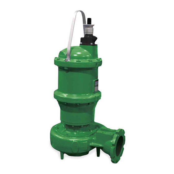
Solids Handling Submersible Pump
#2 Frame
This product may be covered by one or more of the following patents and other patent(s) pending: US Patent 7,931,473 & 8,128,360
These pumps are classifi ed as a Class I Division 1 Groups C&D Explosion-Proof by CSA to NEC and CEC specifi cations. Opening
the motor, including maintenance of the upper mechanical seal, must be performed by CP&S to maintain the certifi cation. Internal
maintenance performed by non-certifi ed personnel will void the explosion-proof rating
IMPORTANT!
Read all instructions in this manual before operating pump.
As a result of Crane Pumps & Systems, Inc., constant product improvement program,
product changes may occur. As such Crane Pumps & Systems reserves the right to
change product without prior written notifi cation.
A Crane Co. Company
420 Third Street
Piqua, Ohio 45356
Phone: (937) 778-8947
Fax: (937) 773-7157
www.cranepumps.com
Manual Index
Series: 7365
3MA
Monovane Pumps
3 - 7.5HP, 1750RPM
3VC
Vortex Pumps
3 - 5HP, 1750RPM
3VR & 3VRA
Vortex Pumps
2 - 10HP, 3450 &
1750RPM
4M & 4ML
Monovane Pumps
3 - 10HP, 1750RPM
83 West Drive, Brampton
P.O. Box 174515
Ontario, Canada L6T 2J6
Jebel Ali, Dubai UAE
Phone: (905) 457-6223
Phone: (971) 4-886-4949
Fax: (905) 457-2650
Fax: (971) 4-886-4950
4D & 4DM
Dual Vane Pumps
3 - 10HP, 1750RPM
4VL
Vortex Pumps
2 - 10HP, 3450 &
1750RPM
4VH
Vortex Pumps
2 - 10HP, 3450 &
1750RPM
4VHA
Vortex Pumps
5 - 10HP, 1750RPM
Form No. 133992-Rev. R
Advertisement
Table of Contents

Related Manuals for Crane Deming 7365-335-26-10N


Summary of Contents for Crane Deming 7365-335-26-10N
- Page 1 Read all instructions in this manual before operating pump. As a result of Crane Pumps & Systems, Inc., constant product improvement program, product changes may occur. As such Crane Pumps & Systems reserves the right to change product without prior written notifi cation.
-
Page 2: Table Of Contents
WARRANTY REGISTRATION ....................28 START-UP REPORT ......................29 - 30 Other brand and product names are trademarks or registered trademarks of their respective holders. ® Deming is a registered trademark of Crane Pumps & Systems, Inc 2018 Alteration Rights Reserved... -
Page 3: Safety First
IMPORTANT! - Crane Pumps & Systems, Inc. is not responsible for losses, injury, or death resulting from a WARNING! - DO NOT pump hazardous materials failure to observe these safety precautions, misuse or (fl... -
Page 4: General Information
For the location of the nearest Deming Service Center, contact personnel to enter the wet well. Place the Break Away Fitting Crane Pumps & Systems, Inc., Service Department in Piqua, (BAF) in position. Temporarily secure the guide rails in the Ohio, telephone (937) 778-8947 or Crane Pumps &... - Page 5 B-3) Liquid Level Controls: The cord assembly mounted to the pump must not be It is recommended to use a liquid level control system modifi ed in any way except for shortening to a specifi c that allows the on and off point to be separated by at least application.
- Page 14 THREE PHASE 460-575 VOLT AC (orange molded plug) THREE PHASE 460-575 VOLT AC (orange molded plug) MOISTURE AND TEMPERATURE SENSORS MOISTURE AND TEMPERATURE SENSORS Power Cable Power Cable Motor Lead ID Motor Lead ID Power Cable Power Cable Lead ID Lead ID Green (Ground) Green...
- Page 15 TYPICAL POWER CIRCUIT FIGURE 3b Single Phase Cap Chart Cap Kit Start Relay Start Cap Run Cap 1750 133042 Mars 64 440MFD @ 330V 50MFD @370V 3450 133043 Mars 64 177MFD @ 330V 40MFD @440V 1750 Single Phase Start Components...
- Page 16 TYPICAL THERMAL PROTECTION WIRING DIAGRAM FIGURE 4 B-4.3) Overload Protection: B-4.4) Moisture Sensors: Current sensing overloads must be provided in the pump A normally open (N/O) detector is installed in the pump seal control panel and should be properly sized for the full load chamber, which will detect any moisture present, and a current of the pump.
-
Page 17: Start-Up Operation
FIGURE 5 It is advisable that all three phase control panels be purchased sensing probes in the motor is intact. This procedure should be from the factory. performed periodically to confi rm integrity of the circuit. SECTION: C START-UP OPERATION C-3) Start-Up Report: Included at the end of this manual is one start-up report sheet, C-1) Check Voltage and Phase:... -
Page 18: Preventative Maintenance
SECTION D: PREVENTATIVE MAINTENANCE IMPORTANT! - Do not overfi ll oil. Overfi lling of seal chamber with oil can As the motor and seal chamber are oil-fi lled, no lubrication or create excessive and dangerous hydraulic other maintenance is required, and generally Deming Pumps pressure which can destroy the pump will give very reliable service and can be expected to operate and create a hazard. - Page 19 E-3) Outer Shaft Seal Service: Make sure the stationary member is in straight and that the rubber ring is not out of it’s groove. Lightly oil (DO NOT CAUTION ! - Handle seal parts with extreme care. use grease) shaft and inner surface of bellows on rotating DO NOT scratch or mar lapped surfaces.
-
Page 20: Replacement Parts
SECTION: F REPLACEMENT PARTS F-1 ORDERING REPLACEMENT PARTS: When ordering replacement parts, ALWAYS furnish the following information: 1. Pump serial number and date code. (Paragraph F-4) 2. Pump model number. (Paragraph F-3) 3. Pump part number. (Paragraph F-2) 4. Part description. 5. -
Page 21: Trouble Shooting
TROUBLE SHOOTING CAUTION ! Always disconnect the pump from the electrical power source before handling. If the system fails to operate properly, carefully read instructions and perform maintenance recommendations. If operating problems persist, the following chart may be of assistance in identifying and correcting them: MATCH “CAUSE”... -
Page 22: Recommended Minimum Suction Clearance (Fig. 9)
DIM. ‘A’ MODEL INCHES NUMBER (MM) ACCESS COVER (SUPPLIED BY OTHERS) 3.00 (76.2) GUIDE RAIL CAP SUPPLIED 3VRA WITH BAF MODELS 3.50 (88.9) INTERMEDIATE SUPPORT ASSY 3.75 (OPTIONAL) REFER (95.3) TO SECTION C-3 2" PIPE GUIDE RAILS (SUPPLIED BY OTHERS) 4.00 (101.6) 4VHA... -
Page 23: Cross-Sections (Fig. 10 & 11)
IMPORTANT! - Service is limited to the following components becuase of the explosion proof rating: impeller, lower mechanical seal, volute and power cord. Service to any other components WILL VOID the warranty and explosion proof certifi cation. Any further work required contact Crane Pumps & Systems. OIL FILL... -
Page 24: Exploded Views (Fig. 12 & 13)
EXPLODED VIEWS Vortex Enclosed FIGURE 13 FIGURE 12 Items Not Shown: 41... -
Page 25: Parts Lists
PARTS LIST ITEM PART NO. DESCRIPTION MATERIAL No Resale Driver Assembly 127223 ♦ π ˃ Screw, SHCS, M12 x 1.75 x 25 18-8 SS 133048 Ring, Retaining, EXT, 5100 420 SS See Table Impeller Ductile Iron Q21-20-J8 ♦ Key, ¼ x ¼ x 1½” 303 SS 136284 ♦... - Page 26 Notes...
-
Page 28: Warranty
Crane Pumps & Systems, Inc. Distributor. RETURNED GOODS RETURN OF MERCHANDISE REQUIRES A “RETURNED GOODS AUTHORIZATION”. CONTACT YOUR LOCAL CRANE PUMPS & SYSTEMS, INC. DISTRIBUTOR. Products Returned Must Be Cleaned, Sanitized, Or Decontaminated As Necessary Prior To Shipment, To Insure That Employees Will Not Be Exposed To Health Hazards In Handling Said Material. -
Page 29: Start-Up Report
A Crane Co. Company START-UP REPORT General Information Pump Owner’s Name: __________________________________________________________ Address: ____________________________________________________________________ Location of Installation: _________________________________________________________ Contact Person: __________________________________Phone: _______________________ Purchased From: _____________________________________________________________ Nameplate Data Pump Model #: ___________________ Serial #: _____________________________________ Part #: __________________________ Impeller Diameter: ____________________________ Voltage: _________ Phase: _____ Ø...
Need help?
Do you have a question about the Deming 7365-335-26-10N and is the answer not in the manual?
Questions and answers