Table of Contents
Advertisement
Quick Links
Advertisement
Table of Contents

Related Manuals for Compex WPE54


Summary of Contents for Compex WPE54
-
Page 2: Trademark Information
© Copyright 2007 Compex Systems Pte Ltd All Rights Reserved This document contains information, which is protected by copyright. Reproduction, adaptation or translation without prior permission is prohibited, except as allowed under the copyright laws. Trademark Information ® Compex is a registered trademark of Compex, Inc. Microsoft Windows and the Windows logo are the trademarks of Microsoft Corp. -
Page 3: Fcc Notice
FCC NOTICE This device has been tested and found to comply with the limits for a Class B digital device, pursuant to Part 15 of the FCC Rules. These limits are designed to provide reasonable protection against harmful interference in a residential installation. This device generates, uses and can radiate radio frequency energy and, if not installed and used in accordance with the instructions, may cause harmful interference to radio communications. -
Page 4: Declaration Of Conformity
Compex, Inc. declares the following: Product Name: Compex Wireless Dual-Band Network Access Point Model No.: Compex WPE54 conforms to the following Product Standards: Radiated Emission Standards: ETSI EN 300 328-2: July 2000; FCC: 47 CFR Part 15, Subpart B, ANSI C63.4-1992; 47 CFR Part 15, Subpart C (Section 15.247), ANSI C63.4-1992. -
Page 5: Technical Support Information
Technical Support Information The warranty information and registration form are found in the Quick Install Guide. For technical support, you may contact Compex or its subsidiaries. For your convenience, you may also seek technical assistance from the local distributor, or from the authorized dealer/reseller that you have purchased this product from. -
Page 6: About This Document
The product described in this document, Compex Wireless Dual-Band Network Access Point, Compex WPE54 is a licensed product of Compex Systems Pte Ltd. This document contains instructions for installing, configuring and using Compex WPE54. It also gives an overview of the key applications and the networking concepts with respect to the product. -
Page 7: Table Of Contents
Copyrights © 2007 Compex Systems Pte Ltd ...i Trademark Information...i Disclaimer ...i Your Feedback...i FCC NOTICE...ii Declaration of Conformity...ii Technical Support Information... iii About This Document ...iv How to Use this Document...iv Firmware………..……….……………….………………………………………………………iv Conventions...iv Chapter 1 Product Overview... 9 Introduction...9 Features and Benefits ...9 When to use which mode ...11 1.3.1... - Page 8 Wireless Extended Features ...44 4.4.1 Access Control – The Wireless Pseudo VLAN...44 4.4.2 Wireless Setup - The Wireless Distributed System (WDS) ...52 4.4.3 WMM Parameters...58 4.4.4 Long Distance Parameters ...61 WLAN Security ...63 4.5.1 How to set up WEP...64 4.5.2 How to set up WPA-PSK...66 4.5.3 How to set up 802.1x/RADIUS ...68...
- Page 9 6.1.6 Reboot System ...113 6.1.7 Change Password...114 6.1.8 Logout...115 Using the HELP menu...116 6.2.1 Get Technical Support ...116 6.2.2 About System ...117 Appendix I Troubleshooting... 118 Solutions to Common Problems...118 Appendix II Firmware Recovery ... 122 AII How to recover the access point from failed firmware...122 Appendix III TCP/IP Configuration...
-
Page 10: Chapter 1 Product Overview
Chapter 2 Hardware Installation Chapter 1 Product Overview Introduction The 54Mbps wireless access point is a compact and high performance access point that is designed with support for high security features like WPA, IEEE 802.1x Authentication and 64-bit or 128-bit Wired Equivalent Privacy. The exclusive wireless LAN technology Wireless Pseudo VLAN further enhances security in wireless hotspot networks in isolating different users into their own VLANs. -
Page 11: Chapter 2 Hardware Installation
Chapter 2 Hardware Installation Smart Select This feature will automatically scan and recommend the best channel that the access point can utilize. Wireless Routing Client Capability The Wireless Routing Client mode enables Internet Service Provider (ISP) or offices to send their data packet wirelessly and these network packets will be routed to a wired Local Area Network via the access point. -
Page 12: When To Use Which Mode
Chapter 2 Hardware Installation Spanning-Tree Protocol provides path redundancy while preventing undesirable loops in the network. It forces certain redundant data paths into a standby (blocked) state. If one network segment in the Spanning-Tree Protocol becomes unreachable, or if Spanning-Tree Protocol costs change, the spanning-tree algorithm reconfigures the spanning-tree topology and re-establishes the link by activating the standby path. -
Page 13: The Access Point Mode
Chapter 2 Hardware Installation 1.3.1 The Access Point Mode This is the default mode of the access point. The Access Point mode enables you to bridge wireless clients to the wired network infrastructure. -
Page 14: The Access Point Client Mode
Chapter 2 Hardware Installation 1.3.2 The Access Point Client Mode In Access Point Client mode, the access point acts as a wireless client that can operate wirelessly with another access point to perform transparent bridging between two Fast Ethernet networks. -
Page 15: The Gateway Mode
Chapter 2 Hardware Installation 1.3.3 The Gateway Mode Or more simply put: Broadband Internet sharing in a wireless network! Since the access point supports several types of broadband connections, the first step in setting up the access point as a Broadband Internet Gateway is to identify the type of broadband Internet access you are subscribed to. - Page 16 Chapter 2 Hardware Installation PPP over Ethernet (PPPoE) Select this type of connection if you are using ADSL services in a country utilising standard PPP over Ethernet for authentication. For instance: If you are in Germany which uses T-1 connection or If you are using SingNet Broadband or Pacific Internet Broadband in Singapore: Singapore ADSL (Ethernet 512K)
-
Page 17: The Wireless Routing Client Mode
Chapter 2 Hardware Installation 1.3.4 The Wireless Routing Client Mode An application of this mode would be for the Ethernet port of the Wireless Routing Client to be used for connection with other devices on the network while access to the Internet would be achieved through wireless communication with wireless ISP. -
Page 18: The Wireless Ethernet Adapter Mode
Chapter 2 Hardware Installation 1.3.5 The Wireless Ethernet Adapter Mode Similarly to the Access Point Client mode, the access point used in this mode, is able to communicate wirelessly with another access point to perform transparent bridging between two networks. However here, the Wireless Ethernet Adapter connects a single wired workstation only. -
Page 19: Chapter 2 Hardware Installation
Chapter 2 Hardware Installation Chapter 2 Hardware Installation Setup Requirements Before starting, please verify that the following is available: CAT5/5e networking cable At least one computer is installed with a Web browser and a wired or wireless network interface adapter TCP/IP protocol is installed and IP address parameters are properly configured on all your network’s nodes... -
Page 20: Hardware Installation
Chapter 2 Hardware Installation Hardware Installation In three simple steps, you may power ON and begin configuring the access point. Use the RJ45 cable to connect the Ethernet port of the access point to your PC. Once you have finished configuring the access point, you can connect the Ethernet cable to your network device, such as to a switch or hub. -
Page 21: Chapter 3 Access To Web-Based Interface
Chapter 3 Access to Web-based Interface Chapter 3 Access to Web-based Interface There are two methods to access to the web-based Interface of the access point: • Through our Utility – uConfig You can access to the web-based interface directly without the need to assign an IP address to your PC. - Page 22 Chapter 3 Access to Web-based Interface Select the access point from the products list and click on Open Web button. This screen prompts you not to exit your uConfig program while accessing to your Web interface, or else you will fail to connect to your device. Click on OK to proceed.
- Page 23 Chapter 3 Access to Web-based Interface At the authentication page, click on the Log On! button to enter the main configuration page. You will then reach the home page of the access point Web interface.
-
Page 24: Direct Access To Web-Based Interface Via Internet Explorer
Chapter 3 Access to Web-based Interface Direct access to web-based interface via Internet Explorer For this method, you need to assign an IP address to your PC so that it belongs to the same subnet as the access point. In this example, we are using Windows XP for illustration, for Windows 98/98SE/2000/NT/ME, kindly refer to Appendix III “TCP/IP Configuration”. - Page 25 Chapter 3 Access to Web-based Interface Next, select on Internet Protocol (TCP/IP) and click on Since the default IP address for the access point is 192.168.168.1, we need to set your PC’s IP address to be the same subnet as your access point. Therefore, in this example, we assign an IP address of 192.168.168.100 and subnet mask as 255.255.255.0.
- Page 26 Chapter 3 Access to Web-based Interface If your TCP/IP settings are correct, you will get replies to the ping command: Launch your Web browser. Under the Tools tab, select Internet Options. Open the Connections tab and in the LAN Settings section, disable all the option boxes.
- Page 27 Chapter 3 Access to Web-based Interface At the Address bar, enter http://192.168.168.1 and press Enter from your keyboard. At the login page, click the 2. You will then reach the home page of the access point’s Web interface. Log On! button to enter the configuration pages.
-
Page 28: Chapter 4 Common Configuration
Chapter 4 Common Configuration Chapter 4 Common Configuration This chapter illustrates the following features, which are available in ALL the operating modes of the access point, unless stated otherwise. • Management Port • WLAN Basic Setup • WLAN Security • STP Setup •... - Page 29 Chapter 4 Common Configuration This table describes the parameters that can be modified in the Management Port Setup page. Parameters Description The LAN IP address of the access point is set by default to 192.168.168.1. IP Address When the DHCP server of the AP is enabled (unless you set a different DHCP Gateway IP Address), this LAN IP Address would also be allocated as the Default Gateway of the DHCP client.
- Page 30 Chapter 4 Common Configuration Always use these Enable this checkbox if you want the access point to only use the DNS server(s) DNS servers you have specified below. Primary DNS IP Your ISP usually provides the IP address of the DNS server. Address Secondary DNS IP This optional field is reserved for the IP address of a secondary DNS server.
-
Page 31: To View The Active Dhcp Leases
Chapter 4 Common Configuration 4.1.1 To view the active DHCP leases The following will guide you to a page display of the active IP address leases that have been allocated by the built-in DHCP server of the access point. View Active DHCP Leases Click on Management Port from the CONFIGURATION menu. -
Page 32: To Reserve Specific Ip Addresses For Predetermined Dhcp Clients
Chapter 4 Common Configuration 4.1.2 To reserve specific IP addresses for predetermined DHCP clients Making an IP address reservation lets you inform the DHCP server to exclude that specific address from the pool of free IP addresses it draws on for dynamic IP address allocation. - Page 33 Chapter 4 Common Configuration Press the Apply button to make your new entry effective. The DHCP Reservations page will then be refreshed to illustrate the currently reserved IP addresses. If you do not need the DHCP server to reserve an IP address anymore, you can delete the DHCP Server Reservation thus:...
- Page 34 Chapter 4 Common Configuration Delete DHCP Server Reservation Select the reserved IP address to delete. Click on Delete. The DHCP Server Reservations table will then be refreshed to reflect your changes. NOTE When creating a DHCP reservation, you can opt to key in either the Host Name or the Hardware Address of the DHCP client.
-
Page 35: Wlan Setup
Chapter 4 Common Configuration WLAN Setup This section shows how to perform the following functions: Basic: This function performs a basic setup of the wireless modes of operation. Security: This function performs data encryption and protection for the router. Advanced: This function furthers the basic configuration of the router by setting the system’s additional parameters such as Access Control, WDS, WMM and Long Distance Parameters. -
Page 36: To Configure The Basic Setup Of The Wireless Mode
Chapter 4 Common Configuration 4.2.1 To configure the Basic setup of the wireless mode The following will guide you to configure the basic setup of the wireless mode you have selected. It also covers the Show Link Information option featured ONLY in wireless client mode. - Page 37 Chapter 4 Common Configuration In the Mode Setup page: The Access Point Name field appears when the access point is in AP/Gateway mode and refers to the identity of the device. When the access point is operated in wireless client mode, this field is referred to as Station Name instead.
- Page 38 Chapter 4 Common Configuration The Wireless Mode drop-down list provides selection environment types in which to operate the access point: • 802.11a only (WPE54AG); • 802.11b only; • 802.11b/g mixed, when both b and g clients are present; • 802.11g only Choose a Country that you are located.
-
Page 39: To Configure The Advanced Setup Of The Wireless Mode
Chapter 4 Common Configuration 4.2.2 To configure the Advanced setup of the wireless mode The following will guide you to configure the advanced setup of the wireless mode you have selected. Advanced Setup Wireless Mode Double-click on WLAN Setup from the CONFIGURATION menu to expand into the four sub-menus. - Page 40 Chapter 4 Common Configuration The Beacon Interval is the amount of time between beacon transmissions. A beacon is a guidance signal sent by the access point to announce its presence to other access points. It also sends information, such as timestamp, SSID, and other parameters regarding the access point to other access points that are within the specified range.
- Page 41 Chapter 4 Common Configuration Ethernet cable is disconnected to the network) If this function is enabled, the wireless radio will be turned off if there is no Ethernet connection. The wireless radio will be turned back on when the Ethernet link is restored.
-
Page 42: Scan For Site Survey
Chapter 4 Common Configuration Scan for Site Survey (For Wireless Client Mode Only) This feature only available in wireless client mode (Access Point Client, Wireless Routing Client and Wireless Ethernet Adapter). When one of the access points is connected to wired network and a set of wireless stations, it is referred to as a Basic Service Set (BSS). - Page 43 Chapter 4 Common Configuration The Site Survey provides a list of the BSS and SSID available, the Chan (channels), Auth (Authentication), Alg (Algorithm) being used, and the strength of the Signal received. To configure to a different SSID: Select radio button corresponding to the SSID you want to configure to.
-
Page 44: Show Link Information
Chapter 4 Common Configuration 4.3.1 Show Link Information (For Wireless Client Mode Only) This function offers a summary of the link data when the access point is in the wireless client mode, i.e., either of the Access Point Client, Wireless Routing Client or the Wireless Ethernet Adapter mode. -
Page 45: Wireless Extended Features
Chapter 4 Common Configuration Wireless Extended Features The Wireless Extended Features are ONLY available when the access point operates in all modes as tabulated below: Features Access Control Wireless Distributed System (WDS) WMM Parameters Outdoor Parameters 4.4.1 Access Control – The Wireless Pseudo VLAN A VLAN is a group of PCs or other network resources that behave as if they were connected to a single network segment. - Page 46 Chapter 4 Common Configuration 4.4.1.1 Wireless Pseudo VLAN Per Node When implemented, this mode isolates each wireless client into its own pseudo VLAN. Wireless clients can therefore access resources on the wired network but are unable to see each other or access each other’s data. The following steps demonstrate how to set up a Wireless Pseudo VLAN per Node.
- Page 47 Chapter 4 Common Configuration 4.4.1.2 Wireless Pseudo VLAN Per Group The access point can configure up to four ‘groups’ of wireless clients identified by their MAC address. Whenever a wireless client requests network access, the access point will first verify whether its MAC address is present in any of the Pseudo VLAN groups.
- Page 48 Chapter 4 Common Configuration The MAC Address List enables you to manage specific VLAN groups by adding or deleting clients through their MAC address. Click on the button. Select a group number from the Group ID drop-down list. Fill in the Mac Addr field with the MAC address of the client in the format xx:xx:xx:xx:xx or xx-xx-xx-xx-xx-xx, where x is...
- Page 49 Chapter 4 Common Configuration Delete client from a group If you want to delete a particular client from a group: Select the client to delete from the Mac Address List. Click on the Delete button. This Delete MAC Address page will appear to confirm whether you want to delete the selected client.
- Page 50 Chapter 4 Common Configuration 4.4.1.3 Tag VLAN - [Available in Access Point mode ONLY] While a port-based VLAN is limited in size since it can only exist within the confines of a single Ethernet switch, a Tag VLAN is designed to extend the wired VLAN to individual wireless clients.
- Page 51 Chapter 4 Common Configuration Select a group number from the Group ID drop-down list. Fill in the Mac Addr field with the MAC address of the client in the format xx:xx:xx:xx:xx or xx-xx-xx-xx-xx, where x is any value between 0-9 and a-f. Click on the Apply button.
- Page 52 Chapter 4 Common Configuration Delete client from a Tag VLAN If you want to delete a particular client from a group: Select the client to delete from the Mac Address List. Click on the Delete button. The Delete MAC Address page will appear to confirm whether you want to delete the selected client.
-
Page 53: Wireless Setup - The Wireless Distributed System (Wds)
Chapter 4 Common Configuration 4.4.2 Wireless Setup - The Wireless Distributed System (WDS) A distribution system links up several of the access points and the areas they serve, creating a wider network in which mobile users can roam while still staying connected to the available network resources. - Page 54 Chapter 4 Common Configuration 4.4.2.2 Chain Configuration WDS A chain configuration WDS spans an area in length, for instance a long corridor. Satellite access points are chained together starting from a root access point. The access points at either end of the chain will have only one WDS port enabled, while the access points in the middle will have two WDS ports configured to associate with the neighboring access points upward and downward in the chain.
- Page 55 Chapter 4 Common Configuration The following steps will guide you in setting up WDS in the access point. WDS Configuration Setup From WLAN Setup under Configuration, click on Advanced which shows the WLAN Advanced Setup page. Go to the Extended Features section.
- Page 56 Chapter 4 Common Configuration On the Add WDS Link screen that appears: Fill up the Partner Address field with the MAC address of the device to include in your WDS, using the format xx-xx- xx-xx-xx-xx xx:xx:xx:xx:xx:xx or a mix of: and -, and where x can take any hexadecimal value 0-9 or a-f.
- Page 57 Chapter 4 Common Configuration If you want to delete a WDS link: Select the radio button on the left of that particular link. Click on the Remove button. An updated WDS Status page will be displayed. To view WDS Statistics Info: Click on the hyperlink of the selected Partner Address.
- Page 58 Chapter 4 Common Configuration NOTE • If WDS Global Control is Disabled, every WDS link will be closed regardless of its status. When WDS Global Control is set to Enabled, the status of every WDS link that you want to include still needs to be individually Enabled. •...
-
Page 59: Wmm Parameters
Chapter 4 Common Configuration 4.4.3 WMM Parameters (available in all modes except for Wireless Bridge Link) Wireless Multimedia (WMM) is a QoS (Quality of Service) standard in IEEE802.11E that we have adopted to improve and support the user experience for multimedia, video, and voice applications by prioritizing data traffic. - Page 60 Chapter 4 Common Configuration The following steps demonstrate how to configure these WMM Parameters. WMM Parameters From WLAN Setup under Configuration, click on Advanced, which shows the WLAN Advanced Setup page. Go to the Extended Features section, and click on the WMM Parameters button.
- Page 61 Chapter 4 Common Configuration Depending on the mode you set up, you have to select either AP (Access Point) or BSS ( Basic Service Set) WMM Parameters. For instance, if the mode is AP, select AP WMM Parameters. The following parameters are described : WMM Parameters (for advanced users) Arbitrary Inter-Frame Space is the minimum wait time interval between the AIFs (Arbitrary Inter-...
-
Page 62: Long Distance Parameters
Chapter 4 Common Configuration 4.4.4 Long Distance Parameters (available in all modes) These parameters determine the distance between wireless clients to ensure that the wireless point-to-point communication takes place efficiently and effortlessly. The following steps demonstrate how to configure these Long Distance Parameters. - Page 63 Chapter 4 Common Configuration The parameters are described below: Outdoor: The Outdoor parameter is disabled by default. If set to Enable, the Outdoor parameters will be configured for outdoor communication over short or long distances specified. Distance: This parameter determines the distance between different buildings. It should be entered in meters.
-
Page 64: Wlan Security
Chapter 4 Common Configuration WLAN Security This section illustrates how to make your WLAN more secure. All the nodes in your network MUST share the same wireless settings to be able to communicate. We will illustrate how to configure each type of security mode individually. To start with, follow the common preliminary steps described below to select the most appropriate security approach for protecting your wireless communications. -
Page 65: How To Set Up Wep
Chapter 4 Common Configuration 4.5.1 How to set up WEP [Available in ALL modes] The guidelines below will help you to set up the access point for using WEP. Security Mode -WEP At the WEP Setup page: Select whether to use WEP 64bit or WEP 128 bit. - Page 66 Chapter 4 Common Configuration When using 128-bit encryption: Your WEP key has to be either 13 alphanumeric characters or 26 hex characters long. Select which of the keys defined to Encrypt data with. Click on Save Reboot the access point. A Hexadecimal value can only take in numbers 0-9 and letters A-F and is NOT case- sensitive.
-
Page 67: How To Set Up Wpa-Psk
Chapter 5 Further Configuration 4.5.2 How to set up WPA-PSK [Available in AP/Gateway mode ONLY] The guidelines below will help you to set up the access point for using WPA- PSK. Please take note that the WPA-PSK, WPA2-PSK and WPA-PSK- AUTO security modes share the same functions). -
Page 68: Chapter 5 Further Configuration
Chapter 5 Further Configuration Press the Save button. Click on Reboot to restart the system, after which your settings will become effective. A Hexadecimal value can only take in numbers 0-9 and letters A-F and is NOT case- sensitive. For selecting WPA2-PSK and WPA-PSK-AUTO, you can use the above procedure of selecting WPA-PSK. -
Page 69: How To Set Up 802.1X/Radius
Chapter 5 Further Configuration 4.5.3 How to set up 802.1x/RADIUS [Available in Access Point mode ONLY] The guidelines below will help you to set up the access point for using 802.1x/RADIUS. Security Mode –802.1x/RADIUS At the WLAN Security Setup page: Select 802.1x mode. -
Page 70: How To Set Up Wpa Eap
Chapter 5 Further Configuration 4.5.4 How to set up WPA EAP [Available in Access Point mode ONLY] The guidelines below will help you to set up the access point for using WPA-EAP. (Please take note that the WPA or WPA1-EAP, WPA2- EAP and WPA-EAP_AUTO have the same functions). - Page 71 Chapter 5 Further Configuration You can key in a different Authentication Port but it MUST match the corresponding port of the RADIUS server. Enter the Shared Secret Key, used to validate client-server RADIUS communications. Specify the Maximum Retransmissions. For greater security, key in the minimum permissible 1, else the maximum allowed is 10.
-
Page 72: Stp Setup
Chapter 5 Further Configuration STP Setup Spanning Tree Protocol (STP) is a link management protocol that helps to prevent undesirable loops occur in the network. For an Ethernet network to function properly, only one active path can exist between two stations. If a loop exists in the network topology, duplication of messages will occur and this might confuse the forwarding algorithm and allow duplicate frames to be forwarded. - Page 73 Chapter 5 Further Configuration To establish path redundancy, STP creates a tree that spans all of the switches in an extended network, forcing redundant paths into a standby, or blocked, state. but establishes the redundant links as a backup if the initial link should fail. If STP costs change, or if one network segment in the STP becomes unreachable, the spanning tree algorithm reconfigures the spanning tree topology and re-establishes the link by activating the standby path.
- Page 74 Chapter 5 Further Configuration The figure shown below explains the implementation of STP in a network. AP#1 is physically connected to a switch whilst another 4 access points (AP#2, AP#3, AP#4 and AP#5) are connected to AP#1 wirelessly. Redundant paths were found in this network, without enabling STP function, broadcast storm will occur in this network, resulted duplicated frames to be forwarded.
- Page 75 Chapter 5 Further Configuration When STP is enabled, the STP-enabled access points will first try to find the root access point using the following criteria: use the access point that is configured with the smallest STP priority. Default priority set in the access points is 32768. If the STP priority values are the same, the access point with smallest MAC address will be chosen as root.
- Page 76 Chapter 5 Further Configuration To explain the effect of STP & Pseudo VLAN on the wireless clients, we will compare 3 separate scenarios. Scenario #1 – (No STP, No Pseudo VLAN) Referring to the illustration below, if the Spanning Tree Protocol (STP) and Pseudo VLAN are not implemented in a network, all clients (Notebook#1, #2, #3 &...
- Page 77 Chapter 5 Further Configuration Scenario #2 – (With STP, No Pseudo VLAN) When STP is enabled, extra redundant network paths between access points will be disabled, hence preventing multiple active network paths in between any two network access points. If one of the access points is down, the STP algorithm will reactivate one of the redundant paths so that the network connection will not be lost.
- Page 78 Chapter 5 Further Configuration Scenario #3 – (With STP and Pseudo VLAN) In this example, both STP and Pseudo VLAN are implemented in this network. All wireless users are unable to communicate with one another. This is one of the measures to ensure data privacy between wireless users in the network.
- Page 79 Chapter 5 Further Configuration Enabling STP Setup Click on STP Setup from the CONFIGURATION menu Select Enable from the STP State radio button. STP State: Activate Spanning Tree Protocol (STP) function makes your network more resilient to link failure and also provides a protection from loop.
-
Page 80: Snmp Setup
Chapter 5 Further Configuration SNMP Setup Simple Network Management Protocol (SNMP) is a set of communication protocols that separates the management architecture from the architecture of the hardware devices. Enabling SNMP Click on SNMP from the CONFIGURATION menu. Select Enable from the SNMP State drop-down list. The default Read Password is set to public while the default Read/Write Password is private. - Page 81 Chapter 5 Further Configuration Enabling MAC Filtering Click on MAC Filtering from the CONFIGURATION menu. Select Enable from the MAC Filtering drop-down list. Click on the button to add in the MAC address of the user. Fill in the Mac Addr field with the MAC address of the client in the format xx:xx:xx:xx:xx or xx-xx-xx-xx-xx-xx, where x is any value within the range 0-...
-
Page 82: Chapter 5 Further Configuration
Chapter 5 Further Configuration Chapter 5 Further Configuration This chapter provides guidelines in: • Setting up uConfig (only in Gateway mode) • Configuring WAN Setup (only in Gateway or Wireless Routing Client mode) • Using NAT • Routing • Implementing IP Filtering •... -
Page 83: Configuring Wan Setup
Chapter 5 Further Configuration Configuring WAN Setup (only available in Gateway and Wireless Routing Client mode) The WAN setup allows you to set up the access point for broadband Internet connection. Described below are the common steps you should start with to select or change the broadband connection type. -
Page 84: Dynamic Ip
Chapter 5 Further Configuration 5.2.1 Dynamic IP In the default dynamic IP addressing mode, your ISP automatically assigns the IP address of the access point to it. This type of connection applies to most Cable Internet subscribers, for instance: • Singapore Cable Vision subscribers. -
Page 85: Static Ip
Chapter 5 Further Configuration 5.2.2 Static IP If you have subscribed to a specific IP address or to a fixed range of IP addresses from your ISP, follow the procedure summarized below. Changing WAN Type – Static IP Configuration At the Static IP WAN Setup page: Replace default... -
Page 86: Pppoe
Chapter 5 Further Configuration 5.2.3 PPPoE Select this connection type if you have subscribed to ADSL in a country utilizing standard PPPoE for authentication, for instance: • If you are in Germany which uses T-1 connection. • If you are a SingNet Broadband or Pacific Internet Broadband user in Singapore. - Page 87 Chapter 5 Further Configuration PPPoE Parameter Description The MTU or Maximum Transmission Unit is the largest packet size allowed by the ISP. It is set by default to 1462 though it can vary between 1400 and 1492. Username This refers to your broadband account username. Password This refers to your broadband account password.
-
Page 88: Singapore Adsl
Chapter 5 Further Configuration 5.2.4 Singapore ADSL Other ADSL subscribers in Singapore, including SingTel Magix SuperSurf users, should opt for this type of connection. Changing WAN Type – Singapore ADSL Configuration At the Singapore ADSL WAN Setup page: Key in the Username of your Internet account. -
Page 89: Australia Bpa Cable
Chapter 5 Further Configuration 5.2.5 Australia BPA Cable This type of connection has been especially customized for Big Pond Cable Internet users in Australia Changing WAN Type – Singapore ADSL Configuration At the Australia BPA WAN Setup page: Key in the Username of your Internet account. -
Page 90: Pptp
Chapter 5 Further Configuration 5.2.6 PPTP The Point-to-Point Tunneling Protocol (PPTP) is a networking technology which, enables the implementation of secure multi-protocol Virtual Private Networks (VPNs) through public networks, enabling remote users to access corporate networks securely at a lower cost Changing WAN Type –... -
Page 91: Using Nat
Chapter 5 Further Configuration Using NAT (Only available in Gateway and Wireless Routing Client mode) NAT, also known as Network Address Translation, functions by transforming the private IP address of packets originating from hosts on your network so that they appear to be coming from a single public IP address and by restoring the destination public IP address to the appropriate private IP address for packets entering the private network. -
Page 92: To Set Up A De-Militarised Zone Host
Chapter 5 Further Configuration 5.3.1 To set up a De-Militarised Zone host A De-Militarised Zone host, or DMZ host, is a separate neutral client sitting between your private network and the WAN. It initiates WAN connections upon request from your network clients, and forwards the request packets. -
Page 93: To Set Up Port Forwarding
Chapter 5 Further Configuration 5.3.2 To set up port forwarding Port forwarding allows the access point to redirect any incoming Internet request bearing a public IP address to a specific PC on your network, based on the incoming packet’s TCP/UDP port number. You can thus use TCP port forwarding to hide your web-server behind the access point for added security while using UDP port forwarding lets you run a secure multiplayer game server. - Page 94 Chapter 5 Further Configuration Set up Port Forwarding – For Known Server Click on NAT from the CONFIGURATION menu. Ensure whether the NAT Status is enabled. At the Advanced NAT Options section: Click on Port Forwarding. The NAT Static Port Based Entries table illustrated by the screen shot displays the list of current port-based entries.
- Page 95 Chapter 5 Further Configuration Set up Port Forwarding – For Custom Server Otherwise, in order to set up Internet applications which are not defined in the Known Server section, go to Custom Server: Key in the Private IP Address. Define the Port numbers to use. Select the relevant Protocol from the drop down list.
- Page 96 Chapter 5 Further Configuration The following is a non-exhaustive list of well-known port numbers: Application Echo Daytime SMTP (Simple Mail Transfer, i.e., email) Telnet Time Name server Gopher WWW (World Wide Web) Port Number...
-
Page 97: Routing
Chapter 5 Further Configuration Routing (Only available in Gateway and Wireless Routing Client mode) The access point supports both static routing so that you can manually add entries into its routing table and dynamic routing, where it will automatically update the routing table, whenever necessary. -
Page 98: Static Routing
Chapter 5 Further Configuration 5.4.1 Static Routing The following will show you how to add entries to your gateway’s routing table so that it may re-route IP packets to another network, which is very useful if your network has more than one router. Static Routing Click on Routing from the CONFIGURATION menu. -
Page 99: Dynamic Routing
Chapter 5 Further Configuration 5.4.2 Dynamic Routing When using dynamic routing, the access point can continuously update its routing table with the latest routing information, thus automatically adjusting to any physical changes in the network topology. The access point supports RIP1 (Routing Information Protocol) and RIP2 (Routing Information Protocol version 2), and periodically broadcasts its routing tables to neighboring routers. -
Page 100: Implementing Ip Filtering
Chapter 5 Further Configuration Implementing IP Filtering (Only available in Gateway and Wireless Routing Client mode) Enabling the IP Filtering function causes the access point to decide, according to predefined rules, whether to block all outgoing packets or to let them pass. The access point provides granularity and latitude in monitoring the traffic in your network by allowing you to define IP filtering rules, based on these 3 factors: •... - Page 101 Chapter 5 Further Configuration IP Filtering Click on IP Filtering from the CONFIGURATION menu. Select either Sent Discarded radio button to accept or reject any packet conforming to the rules. Click on the button to set the new rule in the IP Filter Configuration GUI.
- Page 102 Chapter 5 Further Configuration At the Destination Port drop down list, select either: A Range of TCP ports In this case, you will have to define (From) which port (To) which port, your rule applies. A Single TCP port Here, you need only specify the source port in the (From) field.
- Page 103 Chapter 5 Further Configuration At the Time of the Day drop down list, you may also choose to apply the rule to: A Range of time In which case, you have to specify the time in the format HH:MM, where HH may take any value from 00 to 23 and MM, any value from 00 to 59.
- Page 104 Chapter 5 Further Configuration Delete IP Filtering We illustrated deleting the rule called Finance. To delete an existing IP filtering rule: Select radio button corresponding to the rule to delete. Click on Delete. The Filtering Configuration table will then be refreshed. We illustrated editing the rule called Purchasing.
-
Page 105: Applying Remote Management
Chapter 5 Further Configuration Applying Remote Management (Only available in Gateway and Wireless Routing Client mode) Making use of remote management, you only require Internet access to be able to manage your network. This feature is especially helpful for those who work away from the office or from home. -
Page 106: Enabling Parallel Broadband
Chapter 5 Further Configuration Enabling Parallel Broadband (Only available in Gateway mode) The access point is equipped with the exclusive Parallel Broadband technology, which translates into scalable Internet bandwidth as well as Load Balancing and Fail-Over Redundancy features. Since there is no restriction to the type of broadband Internet account that the access point can connect to, your network may run with one of the access points on Cable Internet, while the rest connect to ADSL. -
Page 107: Fail-Over Redundancy
Chapter 5 Further Configuration 5.7.2 Fail-Over Redundancy In case one of your broadband connections should fail, the affected access point will automatically switch over to other operational broadband channels so that your network is not disrupted. For instance, when the WAN connection to Z is down, Z will redirect its traffic to Y, and hence providing Fail-Over Redundancy of Internet access to wireless clients of Z. -
Page 108: To Enable Parallel Broadband
Chapter 5 Further Configuration 5.7.3 To enable Parallel Broadband Before enabling the Parallel Broadband feature, verify whether: • Each of the access points is correctly configured to connect to its specific broadband Internet account. • You need to enable DHCP on all of the access points in Parallel broadband. -
Page 109: Chapter 6 System Utilities
Chapter 6 System Utilities Chapter 6 System Utilities This chapter provides guidelines in using: • The SYSTEM TOOLS menu • The HELP menu Using the SYSTEM TOOLS Menu 6.1.1 System Identity If your network operates with several of the access points, you would find it useful to have a means of identifying each individual device. -
Page 110: Wlan Station List
Chapter 6 System Utilities 6.1.2 WLAN Station List (Only available in AP mode/Gateway mode) This option allows you to view the wireless clients in the wireless network. WLAN Station List Click on WLAN Station List from the SYSTEM TOOLS menu. Click on the Refresh button to... -
Page 111: Set System's Clock
Chapter 6 System Utilities 6.1.3 Set System’s Clock Synchronizing the built-in clock of the access point with the time kept by your workstation will enable you to effectively manage and operate the time-based functions provided by the access point. Set System’s Clock Click on Set System’s Clock from the SYSTEM TOOLS menu. -
Page 112: Firmware Upgrade
Chapter 6 System Utilities 6.1.4 Firmware Upgrade Our products are designed for upgradeability. You can check the current version of your firmware by clicking on About System from the HELP menu. To begin with, ensure that you have downloaded the latest firmware onto your local hard disk drive. -
Page 113: Save Or Reset Settings
Chapter 6 System Utilities 6.1.5 Save or Reset Settings You may choose to save the current configuration profile, to make a backup of it onto your hard disk, to restore an earlier profile saved on file or to reset the access point back to its default settings. -
Page 114: Reboot System
Chapter 6 System Utilities 6.1.6 Reboot System Most of the changes you make to the system’s settings require a system reboot before the new parameters can take effect. Reboot Your device Click on Reboot System from the SYSTEM TOOLS menu. You will be prompted to confirm whether to execute a system reboot. -
Page 115: Change Password
Chapter 6 System Utilities 6.1.7 Change Password It is recommended that you change the access point login password, which is case sensitive and is set by default, to password. Changing your Password Click on Change Password from the SYSTEM TOOLS menu. Key in the Current Password. -
Page 116: Logout
Chapter 6 System Utilities 6.1.8 Logout To exit the Web interface, follow the next few steps. Click on Logout from the SYSTEM TOOLS menu. Click the Logon button to access the configuration interface again. -
Page 117: Using The Help Menu
Chapter 6 System Utilities Using the HELP menu 6.2.1 Get Technical Support This page presents the contact information of technical support centres around the world. Get Technical Support Click on Get Technical Support from the HELP menu. This is a feature-packed device. If you require further information than provided in the manual or data sheet, please contact a Technical Support Centres by mail, email, fax or telephone. -
Page 118: About System
Chapter 6 System Utilities 6.2.2 About System The About System page displays a summary of your system configuration information. Support technicians might require specific information about your system data when they are troubleshooting your configuration. You can use the information displayed in this page to quickly find the data they need to resolve your system problem. -
Page 119: Appendix I Troubleshooting
Appendix I Troubleshooting Appendix I Troubleshooting Solutions to Common Problems In this section, we list suggested steps to rectify some common problems that may arise during the installation and operation of the access point. 3. I want to know whether the access point is connected to the Internet. A. - Page 120 Appendix I Troubleshooting 4. I am not getting an IP address and am unable to surf the Internet. A. Make sure that the Ethernet cable is properly connecting your Cable/ADSL modem to the WAN port of the gateway, and verify whether the gateway has a valid IP address from the About System page.
- Page 121 Appendix I Troubleshooting 6. I want to set the access point to its factory default settings. G. Power up the gateway. H. Depress the Reset 10 seconds before releasing it. 7. My laptop is not able to access the AP. In the Command Prompt, type ping 192.168.168.1 and press the Enter key.
- Page 122 Appendix I Troubleshooting 8. My network contains several of the access points but they are unable to connect to each other. M. If you are running the Parallel Broadband feature: Though they may belong to different SSIDs, the gateways MUST operate in the same frequency band.
-
Page 123: Appendix Ii Firmware Recovery
Appendix III TCP/IP Configuration Appendix II Firmware Recovery This section demonstrates how to reload the firmware to the access point should the system fail to launch properly. In such cases, the access point will automatically switch to loader mode and the DIAG LED will light up and remain ON. -
Page 124: Appendix Iii Tcp/Ip Configuration
Appendix III TCP/IP Configuration Appendix III TCP/IP Configuration This chapter discusses the configuration of your TCP/IP connection of the access point. Upon the successful installation of the access point, the network adapter will be added to your network folder. To configure TCP/IP connection settings for the access point, please follow the steps listed below. - Page 125 Appendix III TCP/IP Configuration Go through the list of Network Components in the Network window Configuration tab. If TCP/IP is not installed, click on Select Protocol and click Add. Select Microsoft and TCP/IP in the Manufacturers and Network Protocols columns respectively. Click OK. to start the installation...
- Page 126 Appendix III TCP/IP Configuration After TCP/IP is installed, go back to the Network screen and select TCP/IP in the list of Network Components.
- Page 127 Appendix III TCP/IP Configuration Click Properties, and configure the settings in each of the TCP/IP Properties window. NOTE Please check with your system administrator or Internet Service Provider for more information on the TCP/IP parameters.
-
Page 128: Aiii.2 Configure Dynamic Ip Address In Windows Xp/2000
AIII.2 Configure dynamic IP Address in Windows XP/2000 For Windows XP users, you do not need to add the TCP/IP protocol, as it is already setup when a network card is installed. Therefore only the configuration for TCP/IP is needed. - Page 129 Appendix III TCP/IP Configuration Right click on the Wireless Network Connections with the access point and click on Properties. Select the Internet Protocol (TCP/IP) and click Properties. Configure your IP address and the rest of the parameters so that you can be connected to the network.
-
Page 130: Aiii.3 Configure Static Ip Address In Windows 98Se/Me
Appendix III TCP/IP Configuration AIII.3 Configure static IP Address in Windows 98SE/ME Follow Step 1 to 6 in Section AIII.1 “Configure dynamic IP Address in Windows 98SE/ME” on Page 88. Click Properties, and configure the settings in each of the TCP/IP Properties window. -
Page 131: Aiii.4 Configure Static Ip Address In Windows Xp/2000
Appendix III TCP/IP Configuration AIII.4 Configure static IP Address in Windows XP/2000 Follow Step 1 to 6 in Section AIII.2 “Configure dynamic IP Address in Windows XP/2000” on Page 91. Right click on the Wireless Network Connections with the access point and click on Properties. -
Page 132: Appendix Iv Panel Views And Descriptions
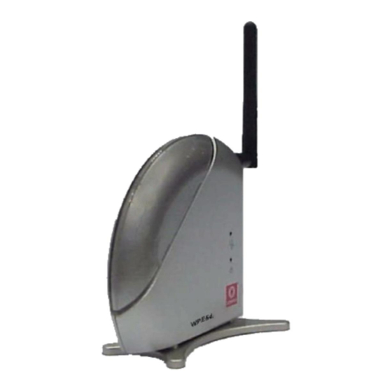
Appendix IV Panel Views and Descriptions Appendix IV Panel Views and Descriptions Features Link/Act Steady Yellow Steady Green WLAN Link/Act Steady Green Blinking Green Diagnostic LED Steady Green Blinking Green Power LED Steady Blue Antenna 2dbi antenna Status and Indications The access point is operating at the speed of 10Mbps. - Page 133 Appendix IV Panel Views and Descriptions Features RJ45 Using RJ45 Ethernet cable for connection. Ethernet Port DC 3.3V 3A Power input of 3.3VDC Reset button Push button: • • • Status and Indications 2s to reboot your device between 2s to 10s to restore to its factory default 10s for operating mode switch...
-
Page 134: Appendix V Technical Specifications
Appendix V Technical Specifications Appendix V Technical Specifications Industrial Standards Performance Frequency Range IEEE 802.11a (WPE54AG): IEEE 802.11b: IEEE 802.11g: Wireless Operation Modes Security Network Interface Modulation Techniques IEEE 802.11a (WPE54AG): IEEE 802.11b/g: Output Power IEEE 802.11a (WPE54AG): IEEE 802.11b: IEE 802.11g: •... - Page 135 Appendix V Technical Specifications Operating Distance IEEE 802.11a (WPE54AG): IEEE 802.11b: IEE 802.11g: Operating Channels Resiliency SNMP LED Indicators Power Requirements Antenna IP Addressing Management IP Addressing Built-in DHCP Server DHCP Reservation Load Balancing Fail-Over Redundancy Virtual Server 85 m (54Mbps outdoor) 20 m (54Mbps indoor) 300 m (11Mbps outdoor) 30 m (11Mbps)
- Page 136 Appendix V Technical Specifications IP Packet Filtering IP Routing VPN Client Pass-Through Configuration Interface Profile Backup & Restore Firmware Upgrade Electromagnetic Emissions Electromagnetic Immunity Safety Power Requirements Input Voltage: Current Ratings: Environment Requirements Operating Temp: Storage Temp: Operating Humidity: Physical Dimensions •...
- Page 137 Manual Number: U-0428-V1.4C Version 1.4 May 2007 cxxxvi...
Need help?
Do you have a question about the WPE54 and is the answer not in the manual?
Questions and answers