Table of Contents
Advertisement
Quick Links
Advertisement
Table of Contents

Subscribe to Our Youtube Channel
Related Manuals for Compex WP54G 6E


Summary of Contents for Compex WP54G 6E
-
Page 2: Trademark Information
Compex, Inc. may make improvements and/or changes to the product and/or specifications of the product described in this manual, without prior notice. Compex, Inc will not be liable for any technical inaccuracies or typographical errors found in this guide. Changes are periodically made to the information contained herein and will be incorporated into later versions of the manual. - Page 3 FCC NOTICE This device has been tested and found to comply with the limits for a Class B digital device, pursuant to Part 15 of the FCC Rules. These limits are designed to provide reasonable protection against harmful interference in a residential installation.
-
Page 4: Declaration Of Conformity
ICES 003 Statement This Class B digital apparatus complies with Canadian ICES-003. Declaration of Conformity Compex, Inc. declares the following: Product Name: Wireless Access Point with Integrated PoE Model No.: WP54G conforms to the following Product Standards: This device complies with the Electromagnetic Compatibility Directive (89/336/EEC) issued by the Commission of the European Community. -
Page 5: Technical Support Information
The warranty information and registration form are found in the Quick Install Guide. For technical support, you may contact Compex or its subsidiaries. For your convenience, you may also seek technical assistance from the local distributor, or from the authorized dealer/reseller that you have purchased this product from. -
Page 6: About This Document
About This Document The product described in this document, Wireless Access Point with Integrated PoE, WP54G is a licensed product of Compex Systems Pte Ltd. This document contains instructions for installing, configuring and using WP54G. It also gives an overview of the key applications and the networking concepts with respect to the product. -
Page 7: Conventions
Conventions In this document, special conventions are used to help and present the information clearly. The Wireless Access Point with Integrated PoE is often referred to as WP54G or Access Point in this document. Below is a list of conventions used throughout. NOTE This section will consist of important features or instructions CAUTION... -
Page 8: Table Of Contents
Copyrights © 2006 Compex Systems Pte Ltd ..............i Trademark Information ..................... i Disclaimer ..........................i Your Feedback........................i FCC NOTICE ........................ii Declaration of Conformity ....................ii Technical Support Information ..................iii About This Document...................... iv How to Use this Document ..................... iv Firmware .......................... - Page 9 To configure the Security setup of the wireless mode....... 43 To configure the Advanced setup of the wireless mode ......43 Statistics......................46 STP Setup........................48 MAC Filtering......................53 Add a MAC address to the MAC Address List..........54 Delete a MAC address from all access points.
- Page 10 APPENDIX I: FIRMWARE RECOVERY .........95 APPENDIX II: TCP/IP CONFIGURATION ........97 For Windows 95/98/98SE/ME/NT ..............97 For Windows XP/2000..................99 APPENDIX III: PANEL VIEWS & DESCRIPTIONS ......102 APPENDIX IV: VIRTUAL AP (MULTI-SSID) FAQ ......105 APPENDIX V: TECHNICAL SPECIFICATIONS ......109...
-
Page 11: Chapter 1: Product Overview
The high-performance access point (AP) is designed enterprise public access applications. Embedded with the Atheros chipset, it boasts network robustness, stability and wider network coverage. Based on 802.11g, the access point supports high- speed data transmission of up to 54Mbps in the 2.4GHz frequency band. -
Page 12: Features And Benefits
This feature will automatically scan and recommend the best channel that the access point can utilize. uConfig Utility Compex’s exclusive uConfig utility allows users to access the user-friendly Web configuration interface of the access point without having to change the TCP/IP setup of the workstation. -
Page 13: When To Use Which Mode
The access point is versatile in the sense that it may operate in 2 different types of modes: Access Point Mode and Client Mode. This section presents a brief outline of the different network applications that can be accommodated through the different modes of the access point. This is the default mode of the access point. -
Page 14: Access Point Client Mode
In Access Point Client mode, the device acts as a wireless client. When connected to an access point, it will create a network link between the Ethernet network connected at this client device, and the wireless and Ethernet network connected at the access point. In this mode it can only connect with an access point. -
Page 15: Chapter 2: Hardware Installation
Before starting, please verify that the following is available: CAT5/5e networking cable At least one computer is installed with a Web browser and a wired or wireless network interface adapter TCP/IP protocol is installed and IP address parameters are properly configured on all your network’s nodes The access point can be powered using either the power adapter provided or a PoE Injector. - Page 16 Insert one end of the Ethernet cable to any of the Ethernet ports on your access point, and the other end of the cable to your PC’s Ethernet network adapter. Attach the power adapter to the main electrical supply, and connect the power plug into the socket of the access point.
-
Page 17: Option Two: Using Poe To Supply Power To The Unit
The access point is fully compatible with a Power-Over-Ethernet (PoE) kit. A PoE accessory supplies operational power to the wireless AP via the Ethernet cable connection. Users who have already purchased a PoE and who wish to use it to supply power to the access point may follow the installation procedures shown below: Connect the external antenna to the SMA connector of the access point. - Page 18 Next, connect the RJ45 Ethernet cable attached to the PoE Injector to your PC’s Ethernet network adapter. Once you have finished configuring your access point, you can connect the PoE Injector’s RJ45 Ethernet cable to your network device, such as to a switch or hub.
- Page 19 Turn on your power supply. Notice that the Power LED has lighted up. This indicates that the access point is receiving power through the Compex PoE Injector. Notice also that the corresponding port LEDs have lighted up. This indicates that connection between your access point and your PC has been...
-
Page 20: Optional: Mounting On The Wall
Screw the mount onto the unit. Align the unit and mount to the wall. Use the mount as a guide, make 2 marks and drill 2 holes into the wall. Next, secure the unit and mount to the wall. -
Page 21: Chapter 3: Access To Web-Based Interface
2 to 254, so that it is in the same subnet as the access point. Compex has developed a powerful uConfig utility that has been designed to give you direct access to the Web interface. - Page 22 When the utility has been installed, double-click on the uConfig icon. The following screen will appear, click on the Yes button to proceed. Select in the section and click on the button. To retrieve and display the latest device(s) in the list, click on the button.
- Page 23 Do not exit the uConfig program while accessing to the web-based interface. This will disconnect you from the device. Click on the OK button to proceed. At the login page, press the button to enter the configuration page. The default password is “password”.
- Page 24 You will then reach the home page of the access point’s web-based interface.
-
Page 25: Manual Access To Web-Based Interface Via Internet Explorer
For this method, you need to assign an IP address to your PC so that it belongs to the same subnet as your access point. In this example, we are using Windows XP for illustration. For Windows 98/98SE/2000/NT/ME, kindly refer to Appendix II “TCP/IP Configuration”. - Page 26 Highlight Internet Protocol (TCP/IP) and click on the button. Select the radio button for Use the following IP address. Enter the IP Address and Subnet Mask as 192.168.168.x and 255.255.255.0, where x can be any number from 2 to 254, except 1. In this example, we are using 192.168.168.160 as the static IP Address.
- Page 27 Click on the button to close all windows. Next, in order to check if the IP address has been correctly assigned to your PC, go to Start menu, Accessories, select Command Prompt and type the command ipconfig/all. Your PC is now ready to configure the access point. Launch your Web browser.
- Page 28 Open the Connections tab and in the LAN Settings section, disable all the option boxes. Click on the button to update the changes. At the Address bar, enter http://192.168.168.1 and press Enter on your keyboard. At the login page, click on the button to enter the configuration pages.
- Page 29 You will then reach the home page of the access point’s Web interface.
-
Page 30: Chapter 4: Common Configuration
This chapter illustrates the following features, which are available in ALL the operating modes of the access point, unless stated otherwise. • Management Port • WLAN Basic Setup • WLAN Security • STP Setup • SNMP • MAC Filtering • Antenna Alignment This section shows you how to customize the parameters of the access point to suit the needs of your network. -
Page 31: Setting Up Your Lan
You can opt to adjust the default values of the access point and customize them to your network settings. Click on Management Port from the CONFIGURATION menu. In the Management Port Setup page, refer to the table below to replace the default settings of the access point with appropriate values to suit the needs of your network. - Page 32 This table describes the parameters that can be modified in the Management Port Setup page. Parameters Description IP Address When the DHCP server of the access point is enabled (unless you set a different DHCP Gateway IP Address), this LAN IP Address would be allocated as the Default Gateway of the DHCP client.
- Page 33 Parameters Description DHCP Gateway IP Though usually, the DHCP server also acts as the Default Address Gateway of the DHCP client, the access point gives you the option to define a different Gateway IP Address, which will be allocated as the Default Gateway IP of the DHCP client. The DHCP client will thus receive its dynamic IP address from the access point but will access to the Internet or to the other LAN through the Default Gateway defined by the DHCP Gateway IP...
-
Page 34: To View The Active Dhcp Leases
The following will guide you to a page display of the active IP address leases that have been allocated by the built-in DHCP server of the access point. Click on Management Port from the CONFIGURATION menu. Go to the Advanced DHCP Server Options section, click on the button. -
Page 35: To Reserve Specific Ip Addresses For Predetermined Dhcp Clients
Making an IP address reservation lets you inform the DHCP server to exclude that specific address from the pool of free IP addresses it draws on for dynamic IP address allocation. For instance, if you set up a publicly accessible FTP/HTTP server within your private LAN, while that server would require a fixed IP address, you would still want the DHCP server to dynamically allocate IP addresses to the rest of the PCs on the LAN. - Page 36 Fill in: The host portion of the IP Address to reserve. The Hardware Address, in pairs of two hex values Press the button to make your new entry effective. The DHCP Server Reservations page will then be refreshed to illustrate the currently reserved IP addresses.
- Page 37 If you do not need the DHCP server to reserve an IP address anymore, you can delete the DHCP Server Reservation. Click on the reserved IP address that you wish to delete, e.g. 192.168.168.20. Click on the button. The DHCP Server Reservations table will then be refreshed to reflect your changes.
-
Page 38: Wlan Setup
This section shows how to perform the following functions: Basic: This function performs a basic setup of the operation modes. Security: This function performs data encryption and protection for the router. Kindly refer to Chapter 5 on WLAN Security for details. Advanced: This function furthers the basic configuration of the router by setting the system’s additional parameters: Virtual AP and Long Distance Parameters. -
Page 39: To Configure The Basic Setup Of The Wireless Mode
The following will guide you to configure the basic setup of the wireless mode you have selected. Click on from the menu. You will see the sub- menus expanded under . Click on The default operating mode of Access point is the Access Point mode. If you wish to change the current mode of your access point, click on , select your and click on the... - Page 41 Enter the parameters in their respective fields, click on the button and reboot your device to let your changes take effect. Note that the pages for the modes are different. Example: page for Example: page for...
- Page 42 This table describes the parameters that can be modified in the WLAN Basic Setup page. Parameters Description The Current Mode The default operating mode of the access point is the Access Point mode. The router can operate in two modes: Access Point mode Client mode You can toggle the mode by clicking on the...
- Page 43 Channel This option allows you to select a frequency channel for (Only in AP mode) the wireless communication. Tx Rate Allow you to choose the rate of data transmission from 2 Mbps to Auto. Closed System The access point will not broadcast its WLAN name (ESSID) when Closed system is enabled.
- Page 44 In the Mode Setup page, click on the button. The Site Survey provides a list of the MAC addresses (BSSID) and SSID of neighbouring access points detected, Chan (channels), Auth (Authentication), Alg (Algorithm) used, and the strength of the Signal received.
- Page 45 To connect the WP54G-client to one of the access points detected: Select the radio button corresponding to the access point you want to connect to. Click on the button to effect the change and return to the setup page. Click on the button to update this screen.
- Page 46 To view the connection status when WP54G-client is linked to another access point, click on the button. The Link Information table illustrates the following data:...
- Page 47 This table describes the parameters that can be viewed from the Link Information page. Parameters Description State Refers to the MAC address of the BSS (AP to which the WP54G-client is connected). Current Channel The channel that is being presently used for transmission. Tx Rate The rate of data transmission in Mbps.
- Page 48 Channel Survey provides a list of all channels that are supported by the access point. This feature will show relative interference of all channels and recommend the least congested channel. When the users want to scan for and find the best channel, they can use Channel Survey.
- Page 49 The values indicate the level of interference. The higher the value, the higher the interference. If the value is zero, there is no interference. To connect the WP54G-client to one of the channels detected, select the radio button corresponding to the channel you want to connect to. Click on the button to effect the change and return to the setup page.
- Page 50 This table describes the read-only parameters of all channels that can be viewed from the Channel Survey page. Parameters Description Freq Refers to the frequency of the channel at which your access point is operating. Channel Refers to the channel of the access point being used for transmission depending on its origin of country.
- Page 51 The Antenna Alignment feature in the access point is designed to precisely align the antenna over such a long distance so that the connectivity communication between your access point and another remote or neighbouring access point could be improved as indicated by higher signal strength.
- Page 52 NOTE If no MAC address is entered, the Antenna Alignment tool will make use of the SSID to align the antenna. Please make sure that the correct SSID is entered. If more than one access point (AP) share the same SSID, the Antenna Alignment tool will show the strongest signal AP.
-
Page 53: To Configure The Security Setup Of The Wireless Mode
Please refer to Chapter 5 on WLAN Security for details on setting the different security modes of the access point. The following will guide you to configure the advanced setup of the wireless mode you have selected. Double-click on WLAN Setup from the CONFIGURATION menu to expand into the four sub-menus. - Page 54 This table describes the parameters that can be modified in the WLAN Advanced Setup page. Parameters Description Beacon Interval The Beacon Interval is the amount of time between (Only in Access beacon transmissions. A beacon is a guidance signal Point mode) sent by the access point to announce its presence to other devices in the network.
- Page 55 Antenna Control The Antenna Control function allows you to control whether to use the: • Main antenna • Aux (auxiliary) antenna • Auto (Default), to monitor the signal from each antenna and automatically switch to the one with better signal NOTE The values illustrated in the examples are suggested values for their respective parameters.
-
Page 56: Statistics
The following shows you the information on the wireless device that is connected to the WLAN. Double-click on WLAN Setup from the CONFIGURATION menu. You will see the sub-menus expanded under WLAN Setup. Click on Statistics. Wireless clients that are connected to the WLAN are shown in the WLAN Station List. - Page 57 Double-click on WLAN Setup from the CONFIGURATION menu. You will see the sub-menus expanded under WLAN Setup. Click on Statistics. In Client mode, you are not allowed to view other wireless clients’ statistics. To view other wireless clients information, you need to change to Access Point mode.
-
Page 58: Stp Setup
Spanning Tree Protocol (STP) is a link management protocol that helps to prevent undesirable loops occurs in the network. For an Ethernet network to function properly, only one active path can exist between two stations. If a loop exists in the network topology, duplication of messages will occur and this might confuse the forwarding algorithm and allow duplicate frames to be forwarded. - Page 59 should fail. If STP costs change, or if one network segment in the STP becomes unreachable, the spanning tree algorithm reconfigures the spanning tree topology and re-establishes the connection by activating the standby path. Without spanning tree in place, it is possible that more than one connection may be simultaneously live, which could result in an endless loop of traffic on the LAN.
- Page 60 Scenario #1 – (No STP) Referring to the illustration below, if the Spanning Tree Protocol (STP) is not implemented in a network, all clients (Notebook#1, #2, #3 & #4,) can access to one another, resulting in low level of data security. Due to the redundant paths found in this network, broadcast packets will be duplicated and forwarded endlessly resulting in a broadcast storm.
- Page 61 Scenario #2 – (With STP) When STP is enabled, extra redundant network paths between APs will be disabled, hence preventing multiple active network paths in-between any two APs. If one of the APs is down, the STP algorithm will reactivate one of the redundant paths so that the network connection will not be lost.
- Page 62 Click on from the menu. Select from the radio button, fill in the fields, and click on button to update the changes. Priority: (Default: 32768, Range: 0 – 65535) This is the relative priority. The lowest priority will be elected as the root. Hello Time: (Default: 2, Range: 1 –...
-
Page 63: Mac Filtering
MAC Filtering acts as a security measure by controlling the users accessing to the network through their MAC address. Each WLAN or radio card supports up to 16 virtual access points and has its own MAC address listing. The client MAC addresses entries can be set apply to all, or to only selected virtual access points. -
Page 64: Add A Mac Address To The Mac Address List
Select from MAC Address Filtering page displays. In this page you may also set the MAC Filtering Status to for access points and set the Policy to either addresses. MAC Filtering set to with Policy to only the MAC addresses in the MAC Filter Address List and deny all other MAC addresses. - Page 65 MAC Filter Address List page displays. Click the button. Add MAC Address page displays.
- Page 66 Enter the MAC Address of the client in the format xx-xx-xx-xx-xx-xx, where x can take any value in the range 0-9 or a-f. Enter the Comment. This describes the MAC Address you have entered. To apply to all virtual access points: Check To apply to specific virtual access point: Select the checkbox of the corresponding Click the button.
-
Page 67: Delete A Mac Address From All Access Points
NOTE Please reboot to effect all changes and new MAC address entries. Select from MAC Address Filtering page displays. Click (This displays the MAC Address List of the radio card.) - Page 68 MAC Filter Address List page displays. Select the checkbox of the MAC address you wish to delete. Click the button. MAC Filter Address List page displays with updated MAC Address List.
-
Page 69: Delete A Mac Address From Individual Access Point
Select from MAC Address Filtering page displays. Click for the corresponding access point. - Page 70 MAC Filter Address List page displays. Select the checkbox of the MAC address you wish to delete. Click the button. MAC Filter Address List page displays with updated MAC Address List.
-
Page 71: Edit Mac Address From The Mac Address List
Select from MAC Address Filtering page displays. Click MAC Filter Address List page displays. Select the MAC address to edit. - Page 72 The Edit MAC Address page displays. Edit the MAC address settings accordingly. Click MAC Filter Address List page displays with updated MAC Address List.
-
Page 73: Chapter 5: Wlan Security
This section illustrates how to make your WLAN more secure. All the nodes in your network MUST share the same wireless settings to be able to communicate. We will illustrate how to configure each type of security mode individually. To start with, follow the common preliminary steps described below to select the most appropriate security approach for protecting your wireless communications. -
Page 74: How To Set Up Wep
The guidelines below will help you to set up the access point for using WEP. At the WEP Setup page,... - Page 75 Specify the key entry type, by selecting either: Use Hexadecimal: Use ASCII Select the Transmission Key from the pull down menu: Key 1 Key 2 Key 3 Key 4 The access point lets you define up to four different transmission keys. It defines a set of shared keys for network security.
-
Page 76: How To Set Up Wpa-Personal
(Only available in Access Point mode) The guidelines below will help you to set up the access point for using WPA-PSK. Please follow the steps below if you have activated WPA-Personal, WPA2- Personal or WPA-Personal-AUTO security modes. At the WPA1/2-PSK Setup page, Specify the key entry type, by selecting either: Passphrase (Alphanumeric characters) Hexadecimal... - Page 77 For WPA-Personal Set the WPA replaces WEP with a strong encryption technology called Temporal Key Integrity Protocol (TKIP) with Message Integrity Check (MIC). For WPA2-Personal Set the Advanced Encryption Standard (AES) is a stronger symmetric 128-bit block data encryption technique. AES is a requirement of WPA2 under the IEEE 802.11i standard.
-
Page 78: How To Set Up 802.1X/Radius
(Only available in Access Point mode) The guidelines below will help you to set up the access point for using 802.1x/RADIUS. At the IEEE 802.1x Setup page, Key in the IP address of the Primary RADIUS Server in your WLAN. You can optionally add in the IP address of a Secondary RADIUS Server, if any. - Page 79 Enter the Shared Secret Key in the field provided. By default, the Broadcast Key Rotation is set as 600 seconds. You may leave this value as its default setting. Select the length of each encryption key: 64- bit 10 hexadecimal or 5 ASCII Text 128-bit 26 hexadecimal or 13 ASCII Text Press the...
-
Page 80: How To Set Up Wpa Enterprise
(Only Access Point mode supports WPA2-EAP and WPA-EAP-AUTO) The guidelines below will help you to set up the access point for using WPA- . Please follow the steps below if you have selected the Enterprise WPA or WPA1- , WPA2- or WPA- -AUTO. - Page 81 By default, the value for Accounting Port is 1813. You can leave this value as it is. This value must be set to be the same as the one in the RADIUS server. Enter the Shared Secret Key used to validate client-server RADIUS communications.
- Page 82 Enter the GTK (Group Transient Key) Updates. This is the length of time after which the access point will automatically generate a new shared key to secure multicast/broadcast traffic among all stations that are communicating with it. By default, the value is 600 seconds. Press the button and reboot your system, after which your settings will become effective.
-
Page 83: Chapter 6: Wireless Extended Features
This section illustrates how to configure the wireless extended features. To start with, follow the common preliminary steps described below. Virtual AP implements mSSID (Multi-SSID) whereby a single wireless card can be setup with up to 16 virtual AP connections with different SSIDs or BSSID (Basic Service Set Identifier) and security modes. - Page 84 Follow these steps to setup Virtual AP. Virtual AP Click on WLAN Setup (a/b/g) from the CONFIGURATION menu. Select Virtual AP. Virtual AP List page displays. • Click Apply to register changes. • Click Clear to clear Virtual AP List. •...
-
Page 85: Preferred Aps (Only Available In Client Mode)
When there is more than one AP with the same SSID, the Preferred APs function allows you define the MAC address of the APs in order of preference. The MAC address at the top of the Preferred APs list has the highest connection preference, and the MAC address at the bottom has the lowest connection preference. -
Page 86: Long Distance Parameters
This setup allows the WP54G to calculate and display suggested values for certain parameters to use to ensure that wireless communication takes place efficiently and effortlessly between physically distant APs. The following steps demonstrate how to configure the Long Distance Parameters. From WLAN Setup under Configuration, click on Advanced, which shows the WLAN Advanced Setup page. - Page 87 As illustrated on the Long Distance Parameters Setup page, the Outdoor feature is disabled by default. Select Enable from the pull down menu. The access point can automatically calculate the values of the parameters to input based on the distance between your access point and the other wireless device.
- Page 88 You can enter the parameters according to the recommended values in the pop-up window, click on the button to update the changes. This table describes the parameters that can be modified in the Long Distance Parameters page. Parameters Description Outdoor The Outdoor parameter is disabled by default.
-
Page 89: Point-To-Point & Point-To-Multipoint Setup
& & You can implement Point-to-Point connection by simply setting one access point as RootAP in Access Point mode and setting the other access points to Transparent Client mode. You can set a root access point and a transparent client to allow point-to-point communication between different buildings and enable you to bridge wireless clients that are kilometres apart while unifying the networks. - Page 90 Select , click on the button and reboot your device to let your changes take effect.
- Page 91 Follow these steps to setup Transparent Client/s. Click on from the menu. You will see the sub- menus expanded under . Click on Ensure that is set to To change , please refer to: Common Configuration – WLAN Setup - To Configure the Basic Setup of the Wireless Mode. Repeat Transparent Client step to add more points to the Point-to-MultiPoint connection.
-
Page 92: Chapter 7: System Utilities
This chapter provides guidelines in using: The SYSTEM TOOLS menu The HELP menu If your network operates with several access points, you would find it useful to have a means of identifying each individual device. You can define the System Identity of the access point to be uniquely identifiable as follows: Click on System Identity from the SYSTEM TOOLS menu. - Page 93 Enter a unique name in the System Name field. Fill in the name of a person to contact in the System Contact field. Fill up the System Location field. If there are multiple devices in your network or building, this entry might help to identify the device location. Click on the button to effect the changes.
-
Page 94: System Clock Setup
Click on System Clock Setup from the SYSTEM TOOLS menu. Select the appropriate time zone from the Select to Change the Time Zone for the Router Location drop-down list. Enable the Auto Time Setting (SNTP) radio button. SNTP stands for Simple Network Time Protocol and is used to synchronise computer clocks. -
Page 95: Firmware Upgrade
Keep your access point updated with the latest capabilities by downloading its latest firmware revision from either of Compex’s corporate web sites at www.compex.com.sg or www.cpx.com before following the next steps. You can check the types and version of your firmware by clicking on About System from the HELP menu. - Page 96 Follow the instructions given during the upgrading process. You need to reboot the system after the firmware upgrade. NOTE The firmware upgrade process must NOT be interrupted otherwise the device might become unusable.
-
Page 97: Backup Or Reset Settings
You may choose to save the current configuration profile, to make a backup of it onto your hard disk, to restore an earlier profile saved on file or to reset the access point back to its default settings. Click on Backup or Reset Settings from the SYSTEM TOOLS menu. To discard configurations made and restore the access point to its initial factory settings, click on button. - Page 98 Click on Backup or Reset Settings from the SYSTEM TOOLS menu. If you want to back up the current settings of your access point onto your hard disk drive, click on the button. Next, save your configuration file to your local disk.
- Page 99 Click on Backup or Reset Settings from the SYSTEM TOOLS menu. If you want to store back the settings that you had previously saved, click on … button. Proceed to the folder where you saved your … configuration file. Click on the button and the system will prompt you to reboot your device.
-
Page 100: Reboot System
Most of the changes you make to the system’s settings require a system reboot before the new parameters can take effect. Click on Reboot System from the SYSTEM TOOLS menu. Click on the button. Wait for the system to reboot and the login page will be displayed. -
Page 101: Change Password
It is recommended that you change the default login password, which is case sensitive and is set by default, to password. Click on Change Password from the SYSTEM TOOLS menu. Key in the Current Password. The factory default is password. Enter the new password in the New Password field as well as in the Confirm Password field. -
Page 102: Logout
To exit the Web interface, follow the next few steps. Click on Logout from the SYSTEM TOOLS menu. Click the button to access your access point’s configuration interface again. -
Page 103: Using The Help Menu
Click on Get Technical Support from the HELP menu. The access point is a feature-packed device. If you require further information than provided in the manual or data sheet, please contact one of Compex’s Technical Support Centres by mail, email, fax or telephone. -
Page 104: About System
The About System page displays a summary of your system configuration information. Support technicians might require specific information about your system data when they are troubleshooting your configuration. You can use the information displayed in this page to quickly find the data they need to resolve your system problem. - Page 105 This section demonstrates how to reload the firmware to the access point should the system fail to launch properly. In such cases, the access point will automatically switch to loader mode and the diagnostic LED will light up and remain ON. The table below illustrates the behavior of the diagnostic LED ( ).
- Page 106 From the Start menu, click Run and type cmd. When the command prompt window appears, type in the following command: X:\recovery\:TFTP -i 192.168.168.1 PUT image_name.IMG, where refers to your CD drive and image_name.IMG to the firmware filename found in the Recovery folder of the Product CD.
- Page 107 Once the hardware has been set up, you need to assign an IP address to your PC so that it will be in the same subnet as your access point. By default, the access point’s IP address is 192.168.168.1; and its subnet mask is 255.255.255.0. You need to configure your PC’s IP address to 192.168.168.xxx;...
- Page 108 Select radio button Specify an IP address. Enter the IP Address and Subnet Mask 192.168.168.X 255.255.255.0, where X can be any number from 2 to 254, except for 1. In this example, we are using 192.168.168.160 as the static IP Address.
- Page 109 In order to check if the IP address has been assigned correctly to your PC, simply go to the Start menu, select Run, and enter the command winipcfg. Select your respective Ethernet Adapter from the drop down list and click OK. Now, your PC is now ready to communicate with the access point Go to your desktop, right click on My Network Places icon and select Properties.
- Page 110 Highlight Internet Protocol (TCP/IP) and click on Properties button. Select the radio button for Use the following IP address. Enter the IP Address Subnet Mask 192.168.168.X 255.255.255.0, where X can be any number from 2 to 254, except for 1. In this example, we are using 192.168.168.160 as the static IP Address.
- Page 111 Next, in order to check if the IP address has been correctly assigned to your PC, go to Start menu, Accessories, select Command Prompt and type the command ipconfig/all. Your PC is now ready to communicate with the access point.
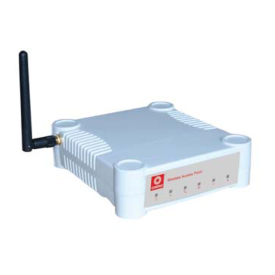
- Page 112 & & Front View of the Access Point Name Description Steady Blue The device is powered up. (Power) No power is supplied to the device. Flashing Green This indicates the flash during the power-up. The LED will goes off when (Diagnostic) the diagnostic is passed.
- Page 113 Steady Green Wireless interface up and running. Ready for operation. (WLAN Flashing Green Activity is detected in the wireless Link/Act LED) network. Steady Green Connection has been established (Port & between device LEDs) network. Flashing Green Activity is detected in the network. No network connection.
- Page 114 Ethernet Port 1 Connection for computer with NIC (Network Interface Card) or Ethernet network card. If using PoE, connect to this port - Ethernet Port 1. DC jack Power Input Reverse SMA connector To attach external antenna Bottom View of the Access Point Name Description Reset Push button...
- Page 115 Q1) What is mSSID? Multi-SSID (mSSID) as the name suggest, allows an access point (AP) with a single radio card to support more than one SSID. Q2) What can you do with mSSID connection? The application of mSSID is to provide better security with multiple network path connections from a single AP, to multiple VLAN network segments of the switch on the local area network.
- Page 116 Q3) Can I update my WP54G or WP54AG to this mSSID firmware? Yes. You can retain your WP54G or WP54AG configuration when you update to the mSSID firmware if the current firmware running is v1.3x and above. If AP is running the following configuration setup, updating to the mSSID firmware will affect the configuration.
- Page 117 Q6) I have Pseudo VLAN for Per Group enabled. Will updating to mSSID firmware still support wireless clients with MAC addresses listed in Per Group? The mSSID firmware replaces Pseudo VLAN and integrates it into VAP (Virtual AP) and MAC Filtering. Thus, Pseudo VLAN with its VLAN ID and MAC listing will be lost after updating to mSSID firmware.
- Page 118 Q8) I have 2 WP54AG units installed at a site about 2km from each other running PtP modes. Should I update to mSSID firmware? Can I do it from one location to update the firmware like I do with the current single SSID firmware? The setup for PtP and PtMP for mSSID firmware is different the current sSSID firmware.
- Page 119 Safety and Electromagnetic FCC Part 15 SubPart B and SubPart C [for wireless Conformance module] EN 300 328-2 [for wireless module] EN 301 489 (EN300 826) [for wireless module] EN 55022 (CISPR 22)/EN 55024 Class B EN 61000-3-2 EN61000-3-3 CE EN 60950 Industrial Standards IEEE 802.11b IEEE 802.11g...
- Page 120 Receiver Sensitivity Up to –90dBm Output Power IEEE 802.11b: 20 dBm IEEE 802.11g: 20 dBm Operating Channels 11 Channels: US and Canada 13 Channels: Europe 14 Channels: Japan Advanced Wireless Features Virtual AP Long Distance Parameters Setup Adjustable transmit power control (in 1dB steps) Smart Select HTTPS Antenna...
- Page 121 Power Requirements Using Power Adapter: Output 24VDC – 48VDC (localized to country of sale) Using PoE: 802.11af PoE Cable Length Requirement 100 meters (max) for PoE Environment Requirements Operating Temp: -20ºC to +70ºC Storage Temp: -65ºC to +100ºC Operating Humidity: 5% to 95% RH Humidity (RH –...
Need help?
Do you have a question about the WP54G 6E and is the answer not in the manual?
Questions and answers