Compex NETPASSAGE Series User Manual
Wireless a+g dualband access point with poe
Hide thumbs
Also See for NETPASSAGE Series:
- User manual (89 pages) ,
- User manual (78 pages) ,
- User manual (121 pages)
Table of Contents
Advertisement
Quick Links
Advertisement
Table of Contents

Related Manuals for Compex NETPASSAGE Series


Summary of Contents for Compex NETPASSAGE Series
-
Page 2: Trademark Information
Compex, Inc. may make improvements and/or changes to the product and/or specifications of the product described in this manual without prior notice. Compex, Inc. will not be liable for any technical inaccuracies or typographical errors found in this guide. Changes are periodically made to the information contained herein and will be incorporated in later versions of the manual. -
Page 3: Fcc Compliance Statement
This device must accept any interference received, including interference that may cause undesired operation. Declaration of Conformity Compex, Inc. declares the following: Product Name: Wireless 54Mbps A+G DualBand Access Point with Integrated PoE Model No: NetPassage WP18 conforms to the following Product Standards:... -
Page 4: Technical Support Information
The warranty information and registration form are found in the Quick Install Guide. For technical support, you may contact Compex or its subsidiaries. For your convenience, you may also seek technical assistance from the local distributor or from the authorized dealer/reseller that you have purchased this product from. -
Page 5: About This Document
The product described in this document, Wireless 54Mbps A+G Dualband Access Point with Integrated PoE, NetPassage WP18 is a licensed product of Compex Systems Pte Ltd. This document contains instructions for installing, configuring and using Compex NetPassage WP18. It also gives an overview of the key applications and the networking concepts with respect to the product. -
Page 6: Table Of Contents
TABLE OF CONTENTS © COPYRIGHT 2006 COMPEX SYSTEMS PTE LTD........I TRADEMARK INFORMATION ................I DISCLAIMER ......................I YOUR FEEDBACK....................I FCC NOTICE ......................I FCC COMPLIANCE STATEMENT..............II DECLARATION OF CONFORMITY ..............II TECHNICAL SUPPORT INFORMATION ............III TECHNICAL SUPPORT CENTRES ..............III ABOUT THIS DOCUMENT ................ - Page 7 How to Setup WPA Enterprise Modes ..............45 How to Setup WPA Personal ................46 ADVANCED WLAN SETTINGS ................47 LONG DISTANCE PARAMETERS ..............49 WMM ........................51 STATISTICS ......................54 VIRTUAL AP (MULTIPLE SSID).................55 PREFERRED APS ....................57 ANTENNA ALIGNMENT..................58 Chapter 6: Configuration................59 SETTING UP THE ACCESS POINT IN YOUR LAN...........59 Setting Up Your LAN ...................61 To View the Active DHCP Leases................62 To Reserve Specific IP Addresses for Predetermined DHCP Clients ....63...
- Page 8 To Setup a De-Militarised Zone Host ..............107 To Setup Port Forwarding .................109 IP Forwarding ....................114 ROUTING ......................116 Static Routing.....................117 BANDWIDTH CONTROL FOR WAN..............119 BANDWIDTH CONTROL FOR LAN ..............120 REMOTE MANAGEMENT .................122 UNIVERSAL PLUG AND PLAY (UPNP)............123 PARALLEL BROADBAND.................125 Load Balancing....................125 Fail-Over Redundancy..................125 To Enable Parallel Broadband ................126 DNS REDIRECTION....................127...
- Page 9 HOW IT WORKS....................165 Appendix C: Troubleshooting..............166 SOLUTIONS TO COMMON PROBLEMS............166 Appendix D Command Line Interface Commands ......... 170 Appendix E Glossary of Terms..............175 LIST OF COMMONLY USED TERMS...............175 Appendix F Technical Specifications ............180...
-
Page 10: Chapter 1: Introduction
Chapter 1: Introduction Introducing the access point His access point is a Wireless 54Mbps A+G Dualband Access Point. It doesn’t just operate in wired network environments, it also upholds simultaneous IEEE802.11a and IEEE802.11b/g connections, as is often required in hotspots and other public Internet access deployment. -
Page 11: Chapter 2: Getting To Know The Access Point
Chapter 2: Getting to know the Access Point The following will help you get more acquainted with the rich suite of features offered by the access point so that you are better able to exploit your access point’s full potential. Key features Point-to-Point &... - Page 12 Easy Management & Configuration You can browse or uConfig to the web interface of the access point for effortless configuration. Additionally, you can make use of these features: • The access point supports HTTPS (SSL) in addition to the standard HTTP. HTTP (SSL) features additional authentication and encryption for secure communication.
-
Page 13: Security Features
Security Features Security elements have been put in place to better protect your data and privacy. WPA (Wi-Fi Protected Access) Standard & 802.1x Authentication The access point supports the WPA standard for enhanced security in your wireless network. The WPA protocol combines two mechanisms: Dynamic Key Encryption and Mutual Authentication for enhanced security in the wireless LAN. -
Page 14: Additional Features
Additional Features These features reveal the comprehensive range of advanced routing functionalities. Static IP, Dynamic IP, PPPoE, PPTP, and L2TP WAN types Whether you have subscribed to fixed IP, dynamic IP, PPPoE, PPTP, or L2TP, you can use the access point for broadband cable /ADSL Internet connection sharing. Parallel Broadband The unique Parallel Broadband technology features improved load balancing and fail-over Internet connectivity. -
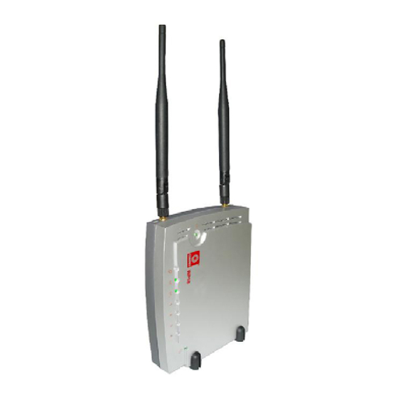
Page 15: Panel Views
Panel Views The access point can either be placed standing upright on the 2 rest feet included or mounted onto a wall. LED indicators denoting network status and activity are situated on the front edge of the access point for easy visibility. Notice: Actual product appearance may slightly differ depending on the hardware version. - Page 16 Front View...
-
Page 17: Panel Description
Panel Description Name Description Power (LED) Steady The device is powered up. Green No power is supplied to the device. WAN (Link/Activity LED) Steady The WAN connection is ON. Green Flashing Data transmission Green connection. WLAN (1), (2) Steady Wireless interface up and (Link/Activity LED) Green running. - Page 18 Rest Feet These rest feet hold the access point in the standing position. External Antennas SMA antennas R232 (Integrated Serial Not in use. Interface) Reserved for future update. WAN (Ethernet Port) 10/100Base-T Port connects to Cable/ADSL modem. 1, 2, 3, 4 (Ethernet Ports) Integrated 3-port 10/100Mbps Switching.
- Page 19 NOTE: Although the Ethernet ports are numbered 1 to 4, they DO NOT have to be connected sequentially. For example: in a network of two computers, you can choose to connect one computer to Port 2 and another to Port 4.
-
Page 20: Chapter 3: Hardware Setup
Chapter 3: Hardware Setup The access point can be powered using either the power adapter, or or IEEE 802.3af PoE. The installation process for the three options is described below. Option 1: Using Power Adapter to Supply Power Before attaching pair Connect the single- external antennas to the access... - Page 21 Insert one end of the RJ45 Ethernet cable to any of the LAN ports (1, 2, 3, or 4) on the access point and the other end to your PC’s Ethernet network adapter. Attach the power adapter to the main electrical supply and connect the power plug into the socket of the access point.
-
Page 22: Option 2: Using Poe To Supply Power
Option 2: Using PoE to Supply Power PoE (Power-Over-Ethernet) can be used to power the access point. This accessory supplies operational power to the wireless access point through the Ethernet cable connection and is available separately. If you wish to use PoE to supply power to the access point, follow the steps below: Follow the steps described in Option One. - Page 23 Connect the RJ45 Ethernet cable attached to the PoE Injector to your PC’s Ethernet network adapter. Once you have finished configuring the access point, you can connect the PoE Injector’s RJ45 Ethernet cable to your network device, such as a switch or a hub. Connect the power adapter supplied in the PoE kit to the main electrical supply and the power plug into the socket of the injector.
- Page 24 Turn on your power supply. Notice that the Power LEDs have lighted up. This indicates that the access point is receiving power through the PoE Injector. Notice also that the Port 4 LEDs have lighted up. This indicates that connection between the access point and your PC has been established.
-
Page 25: Chapter 4: Accessing The Web Interface
Chapter 4: Accessing the Web Interface This chapter consists of the following: Overview of alternatives to access the web interface How to uConfig to the web interface How to browse to the web interface Overview of alternatives The access point can be configured with the web interface. After connecting the access point to your PC, there are two methods of accessing its web interface: Installing and running the uConfig utility. - Page 26 After installation, your PC will automatically detect connected products. Double-click on the uConfig utility icon to run the program. Running uConfig Ensure that the access point is selected under the Products List. Click on Open Web. This opens the access point login screen.
-
Page 27: How To Browse To The Web Interface
How to Browse to the Web Interface Browsing to the web interface Open your Command prompt window type ping 192.168.168.1 to verify that your PC can communicate with the access point. your TCP/IP settings correct, you will get replies to this ping command. -
Page 28: Chapter 5: Setting Up A Wlan
Chapter 5: Setting up a WLAN This chapter applies exclusively to Wireless Setup (a/b/g) and Wireless Setup (b/g). Wireless Setup (a/b/g) supports IEEE 802.11a, IEEE 802.11b only, IEEE 802.11b/g mixed, and IEE 802.11g only wireless LAN connections. Wireless Setup (b/g) supports IEEE 802.11b only, IEEE 802.11b/g mixed, and IEE 802.11g only wireless LAN connections. -
Page 29: Operation Modes
Operation Modes Access Point Mode This is the default mode of your access point. The Access Point mode enables you to bridge wireless clients to access the wired network infrastructure and to communicate with each other. In the example above, the wireless users will be able to access the file server connected to the switch through the access point in Access Point mode. -
Page 30: Client Mode
Client Mode In Client mode, the device acts as a wireless Client. When connected to an access point, it will create a network link between the Ethernet network connected at this Client device, and the wireless and Ethernet network connected at the access point. In this mode it can only connect with an access point. -
Page 31: Wireless Routing Client Mode
Wireless Routing Client Mode An application of this mode would be for the Ethernet port of the Wireless Routing Client to be used for connection with other devices on the network while access to the Internet would be achieved through wireless communication with wireless ISP. -
Page 32: Transparent Client Mode
Transparent Client Mode In Transparent Client Mode, the access point provides connection with an AP acting as Root AP. This operation mode is designed for implementation of Point-to-Point and Point-to-MultiPoint connections. Point-to-Point Point-to-MultiPoint An access point acts as Root AP An access point acts as Root AP and 1 other access point acts as and several other access point acts... - Page 33 Difference Between other client modes and Transparent Client Mode Other client modes Transparent Client Mode Connectivity with any standard Connectivity with RootAP-supported APs. APs. All devices connected to the Devices connected to the Ethernet Ethernet ports use a common ports flow through freely and MAC address for transparently without the MAC communications with the AP.
-
Page 34: To Set Up A Wireless Lan
To Set Up a Wireless LAN Follow these steps to setup your wireless LAN. WLAN Setup (a/b/g) Click on WLAN Setup(a/b/g) from CONFIGURATION menu. Select Basic to make changes. If you disable the card, you will not be able to use the features of this wireless card. - Page 35 The access point supports wireless connectivity that fully compliant with the IEEE 802.11g, IEEE 802.11a, and IEEE 802.11b standards. It also employs different security modes secure data transmission of the wireless clients within your network. The Current Mode is defaulted to Access Point.
- Page 36 Select from the list of wireless modes available: Wireless mode 802.11a (not supported by WLAN Setup for b/g) This mode supports wireless A clients with data rates of up to 54Mbps in the frequency range of 5GHz. 802.11b only This mode supports wireless B clients with data rates of up to 11Mbps in the frequency range of 2.4Hz.
-
Page 37: Point-To-Point & Point-To-Multipoint Setup
Point-to-Point & Point-to-MultiPoint Setup You can implement Point-to-Point connection by simply setting one access point as RootAP in Access Point mode and setting the other access points to Transparent Client mode. You can set a root access point and a transparent client to allow point- to-point communication between different buildings and enable you to bridge wireless clients that are kilometres apart while unifying the networks. - Page 38 Select , click on the button and reboot your device to let your changes take effect.
- Page 39 Follow these steps to setup Transparent Client/s. Click on from the menu. You will see the sub-menus expanded under . Click on Ensure that is set to change please refer Common Configuration – WLAN Setup - To Configure the Basic Setup of the Wireless Mode.
- Page 40 Select the checkbox. Enter the Note: When using , the name must also match the AP’s ESSID name, especially when Closed System is enabled on the Repeat Transparent Client step to add more points to the Point-to- MultiPoint connection.
-
Page 41: Channel Survey
Channel Survey Follow these steps to perform a channel survey to get the recommended channel for the access point. Channel Survey Click on WLAN Setup(a/b/g) from the CONFIGURATION menu. Click Channel Survey to perform a channel survey. The Channel Survey Status page displays with the recommended channel. - Page 42 Channel Survey This table describes the read-only parameters of all channels that can be viewed from the Channel Survey page. Description Parameters Freq Refers to the frequency of the channel at which your access point is operating. Channel Refers to the channel of the access point being used for transmission depending on its origin of country.
-
Page 43: How To Make Your Wlan More Secure
How to Make Your WLAN More Secure All your network clients MUST share the same wireless settings as the access point to be able to communicate. The access point offers 8 types of security modes: Short for Wired Equivalent Privacy, WEP is a security protocol basing on a secret key to encrypt data packets before they are transmitted. - Page 44 WPA2 Enterprise WPA2 Enterprise mode implements the full IEEE 802.11i standard and 802.1X authentication. There MUST be a RADIUS server on your LAN for this security mode to function. WPA Auto Personal WPA Auto Personal mode implements a shared network password for clients and access points and if there are no WPA enabled access points available with the given SSID in WPA Personal mode, the unit will attempt to associate with a non-WPA point with the given SSID, if...
- Page 45 The subsequent sections illustrate how to configure each security mode. Begin with following the two common preliminary steps shown below to select the most appropriate security mode to protect your wireless communications. Selecting a security mode Click on WLAN Setup(a/b/g) from CONFIGURATION menu.
-
Page 46: How To Setup Wep
How to Setup WEP You can define up to 4 WEP keys. For each key, you can specify: Key Entry Method, by selecting either: Hexadecimal ASCII text The encryption level, from the dropdown list: 64-bit 128-bit Click Edit to set the keys, and then click Apply. - Page 47 For hexadecimal key entry: Select the radio button. Select the radio button of the key to be entered. Select the key encryption mode from the drop down menu. Fill in the key value. A hexadecimal value is made of digits 0-9 and letters A-F, and is NOT case-sensitive.
- Page 48 For ASCII key entry: Select the ASCII radio button. Select the radio button entered. Select encryption mode from the drop down menu. Fill in the key value. An ASCII value can take in any alphanumeric character and is NOT case-sensitive. For 64-bit encryption: Your WEP key has to be 5 characters long.
-
Page 49: How To Setup 802.1X
How to Setup 802.1x 802.1x 1. Key in the IP address of the Primary RADIUS Server in your WLAN. Optional: You may also key in a Secondary RADIUS Server, if any. Note: The RADIUS server MUST be in the same subnet as the access point. -
Page 50: How To Setup Wpa Enterprise Modes
How to Setup WPA Enterprise Modes Follow these steps to setup the access point to use WPA Enterprise, WPA2 Enterprise, and WPA Auto Enterprise. WPA Enterprise Select the Cipher Type implement: • TKIP • • AUTO The Cipher Type is set to AUTO by default so that the access point... -
Page 51: How To Setup Wpa Personal
How to Setup WPA Personal Follow these steps to setup the access point for using WPA Personal, WPA2 Personal, and WPA Auto Personal. WPA Personal Fill in the Passphrase or pre- shared network key. Select the Cipher Type implement: • TKIP •... -
Page 52: Advanced Wlan Settings
Advanced WLAN Settings Follow these steps to change the radio settings of the access point. Editing Advanced Settings Click WLAN Setup (a/b/g) from CONFIGURATION menu. Select Advanced. Set the Beacon Interval (the time lapse between every beacon sent) to any value between 200 and 1000. - Page 53 Select whether to enable Station Isolation. This security feature implements isolation, in order to prevent network clients from attacking other network clients. Antenna Control function allows you to control whether to use the: • MAIN antenna (Default) • AUX (Auxiliary) antenna •...
-
Page 54: Long Distance Parameters
Long Distance Parameters It is necessary to adjust the long distance parameters, only if the distance is 100 meters and beyond. Follow these steps to change the long distance parameters of the access point. Editing Long Distance Parameters Click on WLAN Setup (a/b/g) from... - Page 55 1. Select whether Enable Disable Outdoor operation. 2. Enter Distance of the unit in meters. 3. Enter the SlotTime. 4. Enter acknowledgement timeout. 5. Enter the CTS timeout. This dialog box displays if the Distance 6. Click Apply. entered is less than 100 meters. To view recommended long distance parameters: Click Show Reference Data...
-
Page 56: Wmm
Wireless Multimedia (WMM) is a QoS (Quality of Service) standard in IEEE802.11E that we have adopted to improve and support the user experience for multimedia, video, and voice applications by prioritizing data traffic. QoS can be realized through 4 different Access Categories (AC). - Page 57 Follow these steps to change the setup Wireless Multimedia on your access point. Setting WMM Click on WLAN Setup (a/b/g) from CONFIGURATION menu. Select Advanced. Click Settings. Select Enable Wireless Multimedia (WMM) Enter the desired WMM parameters. Using the default parameters is recommended.
- Page 58 WMM Parameters (for advanced users) Arbitrary Inter-Frame Space is the minimum wait time interval AIFs (Arbitrary Inter- between the wireless medium becoming idle and the start of Frame Space) transmission of a frame over the network. Contention Window Minimum is the minimum random wait time Cwmin (Contention drawn from this interval or window for the backoff mechanism on Window Minimum)
-
Page 59: Statistics
Statistics Follow these steps to view the WLAN detailed connections statistics per WLAN station. Statistics Click on WLAN Setup (a/b/g) from CONFIGURATION menu. Select Statistics. 1. Select the WLAN connection to view statistics of. • Click Refresh to refresh the WLAN Connection List. -
Page 60: Virtual Ap (Multiple Ssid)
Virtual AP (Multiple SSID) Virtual AP implements mSSID (Multi-SSID) whereby a single wireless card can be setup with up to 16 virtual AP connections with different SSIDs or BSSID (Basic Service Set Identifier) and security modes. Virtual AP delivers multiple services by VLAN segmentation: making the network think there are many SSIDs available and channeling each connection through different VLANs to the respective virtual network segments on the Ethernet network. - Page 61 Virtual AP Click on WLAN Setup (a/b/g) from the CONFIGURATION menu. Select Virtual AP. Virtual AP List page displays. • Click Apply to register changes. • Click Clear to clear Virtual AP List. • Click Back to return to WLAN Basic Setup page.
-
Page 62: Preferred Aps
Preferred APs (Only available in Client Mode) When there is more than one AP with the same SSID, the Preferred APs function allows you define the MAC address of the APs in order of preference. The MAC address at the top of the Preferred APs list has the highest connection preference, and the MAC address at the bottom has the lowest connection preference. -
Page 63: Antenna Alignment
Antenna Alignment The Antenna Alignment function helps you find the best alignment for the access point antenna by measuring the quality of the signal. For best results during the antenna alignment, turn off all wireless networking devices within range of the access point except the device with which you are trying to align the antenna. -
Page 64: Chapter 6: Configuration
Chapter 6: Configuration This chapter describes the different features of the access point and explains how to customise them to meet your network requirements. Setting up the access point in your LAN SNMP (Simple Network Management Protocol) Setup Setting Up the Access Point in Your LAN The following table lists out the parameters relevant to your LAN setup. - Page 65 respectively, the DHCP End IP Address should be 192.168.168.X where X is any value from 2 to 254. It is preset as 192.168.168.254. Enter the IP address of the gateway to Internet or of the DHCP Gateway IP access point if it is the one connecting to the Internet. Address If your network uses multiple gateways / access points, you may set the access point as DHCP server to a LAN...
-
Page 66: Setting Up Your Lan
Setting Up Your LAN Follow these steps to change the values and customise them for your LAN settings. LAN Setup Click Setup from CONFIGURATION menu. Amend the relevant fields in the LAN Setup page. Click Apply, apply changes. -
Page 67: To View The Active Dhcp Leases
To View the Active DHCP Leases Follow these steps to display the active IP address leases allocated by the built-in DHCP server. To view the active DHCP leases Click LAN Setup from the CONFIGURATION menu. LAN Setup page, go to Advanced DHCP Server Options. -
Page 68: To Reserve Specific Ip Addresses For Predetermined Dhcp Clients
To Reserve Specific IP Addresses for Predetermined DHCP Clients You can reserve a fixed IP address for a predetermined client (identified by its MAC address) to exclude it from the pool of free IP addresses the DHCP server draws on for its dynamic address allocation. For example: If you set up a publicly accessible FTP/HTTP server within your private LAN, that server would require a fixed IP address, whereas you would still want the DHCP server to dynamically allocate IP... - Page 69 If you do not need the DHCP server to reserve an IP address anymore, you can delete the DHCP Server Reservation: Select the reserved IP address to delete. Click Delete. The DHCP Reservations table will refresh reflect the changes.
-
Page 70: Spanning Tree Protocol
Spanning Tree Protocol Spanning Tree Protocol is a link management protocol that provides path redundancy while preventing undesirable loops in the network. For an Ethernet network to function properly, only one active path can exist between two stations. Multiple active paths between stations cause loops in the network. If a loop exists in the network topology, the potential exists for duplication of messages. - Page 71 STP Status: Spanning Tree Protocol (STP) function makes your network more resilient to link failure and avoids loop formation. Priority: Specify the priority given to the AP. This value determines which access point acts as the central reference point, or Root AP, for the STP system —...
-
Page 72: Mac Filtering
MAC Filtering MAC Filtering acts as a security measure by controlling the users accessing to the network through their MAC address. Each WLAN or radio card supports up to 16 virtual access points and has its own MAC address listing. The client MAC addresses entries can be set apply to all, or to only selected virtual access points. -
Page 73: Add A Mac Address To The Mac Address List
Add a MAC address to the MAC Address List. Select from MAC Address Filtering page displays. In this page you may also set the MAC Filtering Status to for access points and set the Policy to either MAC addresses. MAC Filtering set to with Policy to only the MAC addresses in the MAC Filter Address List and deny all other MAC... - Page 74 MAC Filter Address List page displays. Click the button. Add MAC Address page displays.
- Page 75 Enter the MAC Address of the client in the format xx-xx-xx-xx-xx-xx, where x can take any value in the range 0-9 or a-f. Enter the Comment. This describes the MAC Address you have entered. To apply to all virtual access points: Check To apply to specific virtual access point: Select the checkbox of the corresponding AP.
-
Page 76: Delete A Mac Address From All Access Points
Delete a MAC address from all access points. Select from MAC Address Filtering page displays. Click (This displays the MAC Address List of the radio card.) MAC Filter Address List page displays. Select the checkbox of the MAC address you wish to delete. Click the button. - Page 77 MAC Filter Address List page displays with updated MAC Address List.
-
Page 78: Delete A Mac Address From Individual Access Point
Delete a MAC address from individual access point. Select from MAC Address Filtering page displays. Click for the corresponding access point. MAC Filter Address List page displays. Select the checkbox of the MAC address you wish to delete. Click the button. - Page 79 MAC Filter Address List page displays with updated MAC Address List.
-
Page 80: Edit Mac Address From The Mac Address List
Edit MAC address from the MAC Address List. Select from MAC Address Filtering page displays. Click MAC Filter Address List page displays. Select the MAC address to edit. - Page 81 The Edit MAC Address page displays. Edit the MAC address settings accordingly. Click MAC Filter Address List page displays with updated MAC Address List.
-
Page 82: Chapter 7: Security Configuration
Chapter 7: Security Configuration The Security Configuration chapter covers: Firewall Configuration Firewall Logs Packet Filtering URL Filtering Multicast Filtering The access point makes use of Packet Filtering and Stateful Packet Inspection (SPI) to examine each message entering or leaving your LAN and block those that do not satisfy your specified security criteria. -
Page 83: Firewall Configuration
Firewall Configuration Follow these steps to configure the firewall. Firewall Configuration Click Firewall Configuration from Security Configuration menu. Enable the firewall. You can choose the Default Low, Default Medium, or Default High security options convenient setup. Choose the type of network activity information to log for reference. - Page 84 More firewall rules can be added for specific security purposes. Rule Name Enter a unique name to identify this firewall rule. Disposition This parameter determines whether the packets obeying the rule Policy should be accepted or denied by the firewall. Choose between Accept, or Deny.
- Page 85 sends datagrams because congestion. Redirect Informs the host of a preferred route. Time exceeded Indicates that the Time-to-Live (TTL) of an IP datagram has expired. Parameter Informs that host that there is a problem in Problem one the ICMP parameter. Timestamp Information that is from the ICMP data Request...
- Page 86 Check Options This parameter refers to the options in the packet header. The available selection options are abbreviated as follows: SEC – Security LSRR – Loose Source Routing Timestamp – Timestamp RR – Record Route SID – Stream Identifier SSRR – Strict Source Routing RA –...
- Page 87 Rule Number ranges from 1 to Precedence is determined in ascending order such that rule 1 takes precedence over rule 2. Select whether to Deny or to Accept packets Disposition Policy. Pick the relevant Protocol. ICMP Types, select the checkboxes according to the ICMP information gateway to discard/collect.
- Page 88 Similarly, determine Destination Port. 10. Select from Check Options. 11. Select whether packets of TTL Values Equal, Less, Greater, or Not Equal the defined TTL value. 12. Enter value. 13. Click Apply apply settings. NOTE: Up to 40 firewall rules can be defined, with precedence determined by the rule number.
-
Page 89: Firewall Logs
Firewall Logs As described previously, from the Firewall Configuration page the data traffic to be logged by the access point can be defined. The Firewall Log also records any UDP flooding or SYN flooding attacks on your network. Firewall Logs Click Firewall Logs from the... -
Page 90: Packet Filtering
Packet Filtering With Packet Filtering enabled, the access point examines all outgoing packets before deciding - according to predefined rules - whether to block them or to let them pass. The setting of rules to control the network user access should be done by the system administrators. This is equivalent to Time-based Access Management and Internet Application Filtering features as packet-filtering rules based on these 3 factors can be defined:... - Page 91 Follow these steps to setup packet filtering. Packet Filtering Click Packet Filtering from the Security Configuration menu. Clicking Change select Packet Filter Type. Select from three choices: Disabled, Sent, Discarded, then click Apply. The default is Disabled, allowing all packets to be sent. Click Add.
- Page 92 4b). From the IP Address dropdown list, select whether to apply the rule to: Range of IP addresses. Define (From) which IP address (To) which IP address, the rule applies. Single IP address. You need only specify the source IP address in (From).
- Page 93 The format is HH:MM - where take any value from 00 to 23, and can take any value from 00 to time Both (From) (To) may be left blank. Click Apply, to apply the new rule. Filtering Configuration table updates. In this example, the rule BlockCS blocks any IP address (any PCs within the network) from application...
-
Page 94: Url Filtering
URL Filtering The URL Filtering feature of the access point makes it easy to block certain websites from LAN users. URL Filtering Click URL Filtering from the Security Configuration menu. The URL Filter Type can be defined by clicking Change. Selecting Block Select Block or Allow, then click Apply. - Page 95 Selecting Allow In Host Name, enter the web site address to be blocked. For example: www.objectionablewebsites.com Click Add to complete setup.
-
Page 96: Multicast Filtering
Multicast Filtering This feature lets you allow or disallow streaming over the Internet, if you have registered to ISP services providing videos and TV channel streaming. Multicast Filtering Click Multicast from the Security Configuration menu. Enabling filter disallows video streaming over Internet whereas disabling the filter would allow it. -
Page 97: Chapter 8: Enabling And Disabling Router
Chapter 8: Enabling and Disabling Router The unit can operate either as: Access Point Access Point and Router (when routing is enabled) Setting Up as Router The unit operates as a router by default. Follow these steps to enable router operation support. Enable Router Click Enable... -
Page 98: Setting Up As Access Point
Setting Up as Access Point Follow these steps to disable the unit as a router and switch back as an access point. Disable Router Click Setup from CONFIGURATION menu. Click Disable Router. The Disable Router Function appears. Click Disable Router again. For more details on setting up WAN, refer to Chapter 8 Router Setup –... -
Page 99: Chapter 9: Router Setup
Chapter 9: Router Setup This chapter describes the different features when it is set to operate as a router. Broadband Internet Using NAT Routing Remote Management Parallel Broadband DDNS (Dynamic Domain Name System) Setup Features unsuitable for office network: Universal Plug and Play DNS (Domain Name System) Redirection NOTE: Universal Plug and Play and DNS Redirection features are not designed for operation in an office... -
Page 100: Wan Setup
WAN Setup The configuration for each type of broadband Internet connection is shown in the following individual sections. The system has to be restarted to effect changes in settings. Start with these common steps to set the broadband connection type. Changing the WAN Type Click Setup... -
Page 101: Static Ip
Static IP If you have subscribed to a specific IP address or to a fixed range of IP addresses from your ISP, follow these steps. Static IP Configuration Select Static IP Address from Select WAN Type page and click Apply. At the Static IP WAN Setup page: Enter the Address,... -
Page 102: Dynamic Ip
Dynamic IP This is the default WAN Type of the access point. In this connection mode, your ISP will automatically assign its IP address. This connection mode applies to most cable Internet subscribers, for instance: Singapore Cable Vision subscribers. @HOME Cable Service users. Follow these steps to setup Dynamic IP. -
Page 103: Pppoe
PPPoE Select this connection type if you have subscribed to ADSL in a country utilising standard PPPoE for authentication, for instance: If you are in Germany, which uses T-1 connection. If you are a SingNet Broadband or Pacific Internet Broadband user in Singapore. - Page 104 Follow these steps to setup PPPoE. PPPoE Configuration Select PPP over Ethernet from the Select WAN Type menu. At the PPPoE WAN Setup page: Enter your broadband Internet account parameters in the relevant fields. Status section displays your connection settings such as: IP Address Network Mask Gateway IP Address...
-
Page 105: Pptp
PPTP Point-to-Point Tunneling Protocol (PPTP) enables implementation of secure multi-protocol Virtual Private Networks (VPNs) through public networks, enabling secure remote access at lower cost. Follow these steps to setup PPTP. PPTP Configuration Select PPTP as your WAN Type at Select WAN Type page. -
Page 106: L2Tp
L2TP L2TP (Layer 2 Tunneling Protocol) is an extension to the PPP protocol used for Virtual Private Networks (VPNs) that supports multiple protocols and unregistered and privately administered IP addresses over the Internet. Follow these steps to setup L2TP L2TP Configuration Select L2TP as your WAN Type at... - Page 107 Email Notification This feature notifies you by email if there is a change in the WAN IP address. Follow these steps to setup Email Notification. Email Configuration After applying WAN PPPoE Setup, WAN PPTP Setup, or L2TP. The WAN Setup screen of the WAN Type displays.
- Page 108 Email address of Sender: This is the email address that will appear as the sender. Needs Authentication specifies whether the SMTP server requires authentication, and is not selected by default. Click Apply.
-
Page 109: Mac Address Cloning
MAC Address Cloning The access point has the ability to clone MAC addresses. Follow these steps to clone MAC address. MAC Address Cloning Select Setup from Configuration menu. Select MAC Address Cloning from Advanced WAN Options. Click Clone to clone and change the Current MAC. -
Page 110: Link Speed & Duplex
Link Speed & Duplex The access point supports connection link speeds of 100Mbps at full duplex and 10Mbps at half duplex, and can also automatically detect the correct setting. Auto MDIX (Medium Dependent Interface Crossover) feature automatically detects whether a straight-thru or crossover cable is being used. -
Page 111: Using Nat
Using NAT NAT (Network Address Translation) functions by transforming the private IP address of packets originating from hosts on your LAN so that they appear to be coming from a single public IP address, and by restoring the destination public IP address to the appropriate private IP address for packets entering the private network. -
Page 112: To Setup A De-Militarised Zone Host
When NAT is enabled, your LAN is not accessible to the WAN. However, implementing virtual servers allows you to host Internet servers such as web servers, FTP servers or Mail servers on your LAN, in spite of NAT. To Setup a De-Militarised Zone Host If NAT is enabled, a request from the client within the private network first goes to the access point. - Page 113 Click from CONFIGURATION menu. Ensure that NAT Status is set to Enable. At the Advanced NAT Options section: Click DMZ. In the Private IP Address field, enter the IP address of the PC you wish to place within the DMZ. Private IP Address is set to 0.0.0.0 by default.
-
Page 114: To Setup Port Forwarding
To Setup Port Forwarding Port forwarding allows the access point to redirect any incoming Internet request bearing a public IP address to a specific PC on your LAN, based on the incoming packet’s TCP/UDP port number. Hence, using TCP port forwarding, you can hide your web-server behind the access point for added security, while UDP port forwarding lets you run a secure multiplayer game server. - Page 115 Follow these steps to setup port forwarding. Port Forwarding Click from CONFIGURATION menu. Ensure that NAT Status is set to Enable. At the Advanced NAT Options section: Click Port Forwarding.
- Page 116 Port Forward Entries table displays the list of current port-based entries. Click Add. For standard server applications (HTTP/FTP/POP3/Netmeeting), go Known Server: Enter Private Address. Pick appropriate Server Type. Enter the range in the From: and To: fields. Click Add. To set up Internet applications not included under Known Server, go...
- Page 117 NAT Static Port Based Entries reflects the new entry. To assign more servers in your LAN: Click Add. This will bring you back to Add New NAT Port-Based Entry. Repeat Step 3 above. To delete table entries: Select the entry to delete. Click Delete.
- Page 118 The following is a non-exhaustive list of well-known port numbers: Application Port Number Echo Daytime SMTP (Simple Mail Transfer, i.e., email) Telnet Time Nameserver Gopher WWW (World Wide Web)
-
Page 119: Ip Forwarding
IP Forwarding If you have subscribed to more than one IP address from your ISP, you may define Virtual Servers based on their IP address so that incoming Internet requests are forwarded to specific computers within the private network. Assuming you subscribe to the range of Public IP addresses 203.120.12.1 to 203.120.12.62 from your ISP and the PC hosting a server has a LAN IP address of 192.168.168.100: To define the Internet Server as having an IP address of 203.120.12.62,... - Page 120 Enter the Private IP Address of your virtual server as identified in your LAN. Enter the Public IP Address of the server, as known outside your LAN. Click Add. NAT Static IP Address Entries reflects your new entry. To assign more servers in your LAN: Click Add.
-
Page 121: Routing
Routing The access point supports both static routing for manual routing table entry addition, and dynamic routing for automatic routing table update. NOTE: The default settings of the access point allows broadband Internet sharing so there is no need to configure any further routing information. -
Page 122: Static Routing
Static Routing Follow these steps to add entries to your access point’s routing table for rerouting of IP packets to another network. Static Routing Click Routing from CONFIGURATION menu. The IP Routing Table displays the list of current routing entries. To add a static route in the IP Routing Table click Add. - Page 123 The IP Routing Table reflects the new entry. To add more routes: Click Add. This will bring you back to Add IP Route GUI. Repeat Step 3 above. To delete a route: Select the entry to delete. Click Delete. The table will refresh.
-
Page 124: Bandwidth Control For Wan
Bandwidth Control for WAN Bandwidth Control allows you to decide the available bandwidth in levels of 1kbit. Follow these steps to setup Bandwidth Control for WAN. Bandwidth Control for WAN Click Bandwidth Control from CONFIGURATION menu. Select whether to Enable or Disable Bandwidth Control and click Apply. -
Page 125: Bandwidth Control For Lan
Bandwidth Control for LAN Bandwidth Control allows you to decide the available bandwidth in levels of 1kbit. Follow these steps to setup Bandwidth Control for LAN. Bandwidth Control for LAN Click Bandwidth Control from CONFIGURATION menu. Select whether to Enable or Disable Bandwidth Control and click Apply. - Page 126 1. Enter the Bandwidth Control Rule Name. 2. Enter the Committed Rate in kbit. This sets the bandwidth committed. 3. Enter the Ceil Rate in kbit. This is the ceiling rate which sets the maximum bandwidth allowed. 4. Enter the Rule Type Rule Types: •...
-
Page 127: Remote Management
Remote Management This feature is especially helpful for users who work away from the office or from home. The user only requires Internet access to manage the network. Remote Management Click Remote Management from Device Access Management menu. Specify the HTTP / HTTPS Port number. -
Page 128: Universal Plug And Play (Upnp)
Universal Plug and Play (UPnP) The following are issues that can arise when using NAT: Some network applications assume the IP address and port that the • client has been assigned are global routable values that can be used on the Internet directly. Often, this is not the case as the client has been assigned a private IP address that can only be used on the LAN. - Page 129 Although NAT traversal does not solve all NAT-related issues, it allows several applications to run behind NAT-enabled devices. It is recommended that you enable UPnP when running: Multi-player games • Peer-to-peer connections • Real-time communications • Remote Assistance • UPnP Click UPnP Configuration from...
-
Page 130: Parallel Broadband
exclusive! Parallel Broadband The access point is equipped with the exclusive Parallel Broadband technology, which features scalable Internet bandwidth, Load Balancing, and Fail-Over Redundancy. As there is no restriction to the type of broadband Internet account the access point can connect to, your network can run with one access point on Cable Internet, with the rest connected to ADSL at the same time. -
Page 131: To Enable Parallel Broadband
To Enable Parallel Broadband Parallel Broadband can be implemented when: More than one access point is interconnected (LAN port to LAN port) in your network. Each access point is connected to a broadband Internet account. Parallel Broadband Click Parallel Broadband from CONFIGURATION menu. -
Page 132: Dns Redirection
DNS Redirection DNS Redirection allows you to redirect DNS requests to a local or closer DNS server. This improves the response time and enables true plug-and- play accessibility, especially if your DNS server is behind a firewall or is situated on your private LAN. DNS Redirection Click DNS Redirection... -
Page 133: Dynamic Dns Setup
Dynamic DNS Setup It is difficult to remember the IP addresses used by computers to communicate on the Internet. It gets even more complicated when ISPs change your public IP address regularly, as is the case when the Internet connection type is Dynamic IP or PPPoE with Dynamic IP. If you are doing some web hosting on your computer and are using Dynamic IP, Internet users would have to keep up with the changing IP address before being able to access your computer. - Page 134 On Enable/Disable Dynamic DNS page, Dynamic DNS Status is disabled by default. If you have already created a list earlier, click Refresh to update the list. To add a new Dynamic DNS to the list, click Add. Choice DDNS Provider page displays. There are two default providers that you can use.
- Page 135 There are two predefined DDNS providers. Please note that you need to be connected to the Internet to register your DDNS account. To select 2MyDNS – Dynamic DNS Service Provider as DDNS Service Provider Under the Choice column in the Choice DDNS Provider check the radio button for 2MyDNS –...
- Page 136 Optional: In the Mail Exchanger field, enter the Static WAN IP address of the mail server configured to handle email for your domain. Select Backup Mail Exchanger enable this service. Click Add button to save the new addition. Dynamic DNS list table displays the new domain.
- Page 137 To select DtDNS as DDNS Service Provider Under the Choice column in the Choice DDNS Provider check the radio button for DtDNS. Click Next. At the Dynamic DNS Add page: Enter your Domain Name. Select Auto Detect to detect your current WAN IP address.
-
Page 138: Snmp Setup
SNMP Setup SNMP (Simple Network Management Protocol) is a set of protocols that facilitates the exchange of management information between network devices. It enables network administrators to manage network performance, detect and solve network problems, and plan for network growth. Follow these steps to setup SNMP. -
Page 139: Snmp Trap
SNMP Trap The SNMP Trap provides notification of significant network events through unsolicited SNMP messages. This results in substantial savings of network resources by eliminating the need for unnecessary SNMP requests. Follow these steps to setup SNMP Trap. SNMP Trap Click SNMP Setup... -
Page 140: Telnet/Ssh Setup
Telnet/SSH Setup Telnet allows a computer to remotely connect to the access point CLI (Command Line Interface) for control and monitoring. SSH (Secure Shell Host) establishes a secure host connection to the access point CLI for control and monitoring. - Page 141 Follow these steps to setup Telnet/SSH. Telnet/SSH Setup Click Telnet/SSH Setup from the Device Access Management menu. enable Telnet Server: Select Telnet Server Enable and enter the Port Number. To enable SSH server: Select SSH Server Enable and enter the Port Number. Click Apply.
-
Page 142: User Management
User Management User Management Click User Management from the Device Access Management menu. To add user: 1. Click Add button. 2. In Add User Entry Page, enter User Name, Password, Confirm Password, specify whether to allow Telnet/SSH, and specify whether user is granted permission to Read Only or Read/Write, specify whether to allow SNMPV3, and specify... -
Page 143: Telnet Cli
TELNET CLI Telnet CLI (Command Line Interface) The user may connect to the CLI (Command Line Interface) via a TELNET session to the default IP, 192.168.168.1. This section uses Microsoft TELNET command for instruction. You may use any TELNET client. Connecting to CLI (Command Line Interface) via TELNET Connect to CLI (Command Line Interface) with the following command at DOS prompt. -
Page 144: Ssh Cli (Secure Shell Host Command Line Interface)
SSH CLI (Secure Shell Host Command Line Interface) SSH CLI (Secure Shell Host Command Line Interface) SSH is designed and created to provide the best security when accessing another computer remotely. Not only does it encrypt the session, it also provides better authentication facilities and features that increase the security of other protocols. - Page 145 SSH CLI has a command line interface like shown below for example.
-
Page 146: Web Management Setup
Web Management Setup HTTPS (SSL) is supported in addition to the standard HTTP. HTTP (SSL) features additional authentication and encryption for secure communication. Follow these steps to setup web management. Web Management Setup Make selection from the Device Access Management menu. - Page 147 Web service restarts automatically. Web session logouts. You may reconnect using the new web service using the relogin link displayed on the IP address or Web Mode changed page.
-
Page 148: Chapter 10: Web Interface Utilities
Chapter 10: Web Interface Utilities This chapter describes the use of: The System Tools menu The Help menu Using the SYSTEM TOOLS Menu Ping Utility The Ping Utility works like the commonly used Ping.exe program in Command Prompt. It allows pinging of IP addresses or domain names. Follow these steps to use the Ping Utility. - Page 149 The Ping Utility pings the target with 10 packets of 56 bytes data and displays the results and statistics at the end. Click Back to return to the previous Ping Utility page.
-
Page 150: Syslog
Syslog Syslog forwards system log messages in a network to a machine running a Syslog listening application. It is used to help in managing the computer system and increase security on the network. Freeware supporting Syslog is widely available for download from the Internet. This section shows how to: •... - Page 151 Select to Enter the Enter the Click to make the changes. Follow these sample steps to view logged information: Search for a Syslog listening application. Select a Syslog listening application. Download Syslog listening application.
- Page 152 Install Syslog listening application. View logged information on Syslog listening application.
-
Page 153: To Identify Your System
To Identify Your System If your network operates with several access points, a means of identifying each individual access point would be useful. In certain cases your ISP might request identification before dynamically allocating an IP address. The System Name of the access point can then serve as a DHCP Client ID during negotiations with the DHCP Server of your ISP. -
Page 154: To Upgrade The Firmware Version
Follow these steps to set your system’s clock. System Clock Setup Click System Clock Setup from System Tools menu. Choose the correct time zone and Enable the Auto Time Setting (SNTP) using time server such time.nist.gov Click Apply. To Upgrade the Firmware Version The products are designed for upgradability. -
Page 155: Settings Profile
Ensure that the latest firmware has been downloaded onto your local hard disk drive. Enter the path and file name of the downloaded file in Upgrade Firmware (path and file name). Alternatively, click Browse locate the file. Click Upgrade. Follow the instructions given during the upgrading process. - Page 156 To save current profile: Click Save. Restart system to ensure the right profile is being used. To backup current settings onto hard disk drive: Click Backup. Backup return system earlier configuration using backup file: Click Browse to search for backup file. Or enter file path name in Restore Machine’s...
-
Page 157: To Reboot
To Reboot Most changes in system settings require rebooting to take effect. Follow these steps to reboot the access point. Reboot System Click Reboot AP from the System Tools menu. You will be prompted to confirm reboot. Click to reboot the access point. -
Page 158: Change Your Login Password
Change Your Login Password The login password is required to access the web configuration interface, through which the access point settings can be monitored Follow these steps to change password. Change Password Click Change Password from System Tools menu. Note: Password is case-sensitive. Enter Current Password. -
Page 159: To Logout
To Logout Follow these steps to logout. Logout Click Logout from the System Tools menu. A login prompt displays. access configuration interface again, click LOGIN! -
Page 160: Using The Help Menu
Using the HELP Menu To Get Technical Support This page contains the contact information of worldwide technical support centres. Follow these steps to access the page: Get Technical Support Click Get Technical Support from the HELP menu. The access point is feature-packed and highly customisable. -
Page 161: About Your System
About Your System The About System page displays a summary of system configuration information that might be required by support technicians during troubleshooting. Follow these steps to view the settings. About System Click About System from the HELP menu. System Information page displays a summary of the access... -
Page 162: Appendix A: Configuring Your Pc For Network Access
Appendix A: Configuring Your PC for Network Access This section illustrates the configuration of your computer’s TCP/IP settings for communication with the access point or other network computers. Configurations: Adding TCP/IP protocol for Windows 98/98SE/ME/2000 Configuring Dynamic IP Address Allocation for Windows 98/98SE/ME/2000 Configuring Static... - Page 163 Double-click the Network icon. The network configuration screen displays. Check your list network components network window’s configuration tab. If TCP/IP is not installed: Click Add. Select Protocol. Click Add. On the next screen: Select Microsoft from Manufacturers. Select TCP/IP from Network Protocols.
-
Page 164: Configuring Dynamic Ip Address Allocation
Configuring Dynamic IP Address Allocation Microsoft Windows 98/98SE/ME/2000 Follow these steps to configure your PC for dynamic IP address allocation. Dynamic IP address allocation in Windows 98/98SE/ME/2000: Click Start. Select Settings. Click Control Panel. Double-click Network icon. Network configuration screen displays. network window’s Configuration... - Page 165 1. Click Address. Select Obtain an IP address automatically. Click Gateway. Check that Installed Gateways list is blank. Click OK. Network dialog page displays. Click close windows and reboot your computer.
-
Page 166: Configuring Static Ip Address Allocation
Configuring Static IP Address Allocation Microsoft Windows 98/98SE/ME/2000 Follow these steps to enable static IP address allocation. Static IP address allocation in Windows 98/98SE/ME/2000: Click Start. Select Settings. Click Control Panel. Double-click Network. Network screen displays. Network window’s Configuration tab, select the TCP/IP component corresponding to your Ethernet... - Page 167 Click Address. Select Specify an IP address. Address enter 192.168.168.X, where any value from 2 to 254. For example: 192.168.168.45 Enter 255.255.255.0 Subnet Mask. Click Gateway. Enter the IP address of the access point in Gateway. The default IP address of the access point is 192.168.168.1 Click Add.
-
Page 168: Configuring Wireless Network Settings For Windows Xp
Configuring Wireless Network Settings for Windows XP It is recommended to configure the wireless client PC or notebook with automatic IP addressing. Follow these steps to configure your wireless network settings. Microsoft Windows XP: Right-click Wireless Network Connection corresponding wireless Ethernet adapter to be connected to the access point. -
Page 169: Appendix B: Dual Card Application Example
Appendix B: Dual Card Application Example This is an application example for a dual WLAN card access point installed with the following setup: a) One WLAN card as AP (Access Point) mode and the other WLAN card as WRC (Wireless Routing Client) mode. -
Page 170: How It Works
How it works 1. The connection path when WPC-1 is connected to VAP-WLAN1 flows from AP to the Ethernet port of the access point to switch VLAN ID segment 10, WPC-2 flows to VLAN ID segment 20, and WPC-3 flows to WLAN ID segment 30. 2. -
Page 171: Appendix C: Troubleshooting
Appendix C: Troubleshooting Solutions to Common Problems In this section we list suggested steps to rectify some common problems that may arise during the installation and operation of the access point. 1. I want to know whether my PC is connected to the access point and to the Internet. - Page 172 2. I am unable to surf the Internet. A. Make sure that the Ethernet cable is properly connecting your Cable/ADSL modem to the WAN port of the access point, and verify whether the access point has a valid IP address from the About System page.
- Page 173 ♦ Netscape 4.7 later versions Start Netscape Navigator. From the Edit menu bar, select Preferences, then Advanced, and finally Proxies. Make sure that the direct connection to the Internet option is selected. Close all windows to finish. I want to reset the default login password of the access point. A.
- Page 174 If it does, click on it and press the Properties button. Check whether Device Status displays this message “This device is working properly”. If it does not, you will need to uninstall and re-install the software driver. C. Verify whether your access point and your laptop and/or other wireless clients have been configured with the same SSID, which is the case-sensitive name of the wireless network that you are trying to access, and the same WEP settings.
-
Page 175: Appendix D Command Line Interface Commands
Appendix D Command Line Interface Commands Get Operation List SYNTAX DESCRIPTION Get tasks Display all active process/tasks. Get sysinfo Display system information. Get aplist Display list of access points discovered. Get athstats Display wireless driver information. Get brinfo Display bridge and interfaces information. Get brmacshow Display bridge learned MAC address list. - Page 176 TX Rate SYNTAX DESCRIPTION Set txrate <string> Values are: (default auto) (802.11a)-- 6, 9, 12, 18, 24, 36, 48, 54, auto (802.11b/g mixed)-- 1, 2, 5,5, 11, 6, 9, 12, 18, 24, 36, 48, 54, auto (802.11b-only)-- 1, 2, 5.5, 11, auto Wireless Mode SYNTAX DESCRIPTION...
- Page 177 {CTRY_EL_SALVADOR, "SV" }, {CTRY_ESTONIA, "EE" }, {CTRY_FINLAND, "FI" }, {CTRY_FRANCE, "FR" }, {CTRY_FRANCE2, "F2" }, {CTRY_GEORGIA, "GE" }, {CTRY_GERMANY, "DE" }, {CTRY_GREECE, "GR" }, {CTRY_GUATEMALA, "GT" }, {CTRY_HONDURAS, "HN" }, {CTRY_HONG_KONG, "HK" }, {CTRY_HUNGARY, "HU" }, {CTRY_ICELAND, "IS" }, {CTRY_INDIA, "IN"...
- Page 178 {CTRY_SPAIN, "ES" }, {CTRY_SWEDEN, "SE" }, {CTRY_SWITZERLAND, "CH" }, {CTRY_SYRIA, "SY" }, {CTRY_TAIWAN, "TW" }, {CTRY_THAILAND, "TH" }, {CTRY_TRINIDAD_Y_TOBAGO, "TT" }, {CTRY_TUNISIA, "TN" }, {CTRY_TURKEY, "TR" }, {CTRY_UKRAINE, "UA" }, {CTRY_UAE, "AE" }, {CTRY_UNITED_KINGDOM, "GB" }, {CTRY_UNITED_STATES, "US" }, {CTRY_URUGUAY, "UY"...
- Page 179 WLAN State SYNTAX DESCRIPTION Get wlanstate Display whether status of current wireless operation is Enabled or Disabled. Set wlanstate enable/disable Set to Disable to turn off wireless operation. Set to Enable to turn back on wireless operation. Note: When executing this command, please ensure that you are not connected on wireless with device or you will be disconnected from the device and network.
-
Page 180: Appendix E Glossary Of Terms
Appendix E Glossary of Terms List of Commonly Used Terms 10Base-T An IEEE Ethernet standard for 10Mbps data transmission using unshielded twisted pair wires. 100Base-Tx An IEEE Ethernet standard for 100Mbps data transmission using two pairs of Category 5 UTP wire. 802.11b An IEEE standard for wireless networking standard specifying a maximum data transmission rate of 11Mbps using DSSS modulation and... - Page 181 DSSS Direct Sequence Spread Spectrum is a modulation scheme employed by the 802.11b standard that uses a chipping code (redundant bit) during its transmission to reject interference. Dynamic IP Address It is an IP address that is dynamically allocated or assigned to a client device within a TCP/IP network, typically by a DHCP server.
- Page 182 protocol allow a host to inform its local access point, using Host Membership Reports, that it wants to receive messages addressed to a specific multicast group. All hosts conforming to level 2 of the IP multicasting specification require IGMP. IEEE It is the Institute of Electrical and Electronic Engineers.
- Page 183 PPTP Point-to-Point Tunneling Protocol supports the creation of Virtual Private Networks by ensuring that messages transmitted from one VPN node to another are secure. Users can use PPTP to dial in to their corporate network via the Internet. Preamble A preamble is a signal used in network communications to synchronize the transmission timing between two or more systems.
- Page 184 Wired Equivalent Privacy is a wireless data privacy encryption protocol based on a 64-bit or 128-bit shared key algorithm. WLAN Wireless Local Area Network is a group of computers and associated devices that communicate with each other wirelessly.
-
Page 185: Appendix F Technical Specifications
Appendix F Technical Specifications Safety • FCC Part 15 SubPart B and SubPart C [for Electromagnetic wireless module] Conformance • EN 300 328-2 [for wireless module] • EMC CE EN 301 489 (EN300 826) [for wireless module] • EN 55022 (CISPR 22)/EN 55024 Class B •... - Page 186 Network Interface WAN Interface: 1 x 10/100 Mbps LAN Interface: 3 x 10/100 Mbps Power over Ethernet: 1 x PoE Security • 64 - bit / 128 – bit WEP • WPA Personal • WPA Enterprise • WPA2-Personal • WPA2-Enterprise •...
- Page 187 Certifications • • CE Mark • Gost • C-tick N 12030 Environment Requirements Operating Temp: 0ºC to 55ºC Storage Temp: -20ºC to 75ºC Operating Humidity: 10% to 80% RH Humidity (RH – Relative Humidity): Antenna Configuration (WP18 1A) ANT-1: WLM54AG (a/b/g) card MAIN ANT-2: WLM54AG (a/b/g) card AUX Antenna...
Need help?
Do you have a question about the NETPASSAGE Series and is the answer not in the manual?
Questions and answers