Table of Contents
Advertisement
Advertisement
Table of Contents

Related Manuals for Compex wp54g 1a


Summary of Contents for Compex wp54g 1a
-
Page 2: Trademark Information
Compex, Inc. may make improvements and/or changes to the product and/or specifications of the product described in this manual, without prior notice. Compex, Inc will not be liable for any technical inaccuracies or typographical errors found in this guide. -
Page 3: Fcc Notice
FCC NOTICE This device has been tested and found to comply with the limits for a Class B digital device, pursuant to Part 15 of the FCC Rules. These limits are designed to provide reasonable protection against harmful interference in a residential installation. -
Page 4: Declaration Of Conformity
Compex, Inc. declares the following: Product Name: Compex Wireless-G 54Mbps XR Access Point Model No.: Compex WP54G 1a conforms to the following Product Standards: This device complies with the Electromagnetic Compatibility Directive (89/336/EEC) issued by the Commission of the European Community. -
Page 5: Technical Support Information
The warranty information and registration form are found in the Quick Install Guide. For technical support, you may contact Compex or its subsidiaries. For your convenience, you may also seek technical assistance from the local distributor, or from the authorized dealer/reseller that you have purchased this product from. -
Page 6: About This Document
The document is written in such a way that you as a user will find it convenient to find specific information pertaining to the product. It comprises of chapters that explain in details on the installation and configuration of Compex WP54G. Firmware This manual is written based on Firmware version 1.02 build 1115. - Page 7 CAUTION This section concerns risk of injury, system damage or loss of data WARNING This section concerns risk of severe injury References on Menu Command, Push Button, Radio Button, LED and Label appear in Bold. For example, “Click on Ok.”...
-
Page 8: Table Of Contents
Hardware Installation ..................11 OPTION One: Using power adapter to supply power to WP54G .... 11 OPTION Two: Using Compex PoE to supply power to WP54G ....13 CHAPTER 3: ACCESS TO WEB-BASED INTERFACE....16 Access to the Web interface with uConfig............16 Verify the IP address of Compex WP54G with NpFind ........20... - Page 9 Table of Contents CHAPTER 4: COMMON CONFIGURATION ......26 Management Port Setup ...................26 Setting up your LAN ..................27 To view the active DHCP leases ..............30 To reserve specific IP addresses for predetermined DHCP clients..31 WLAN Setup ......................34 To configure the Basic setup of the wireless mode ........35 To configure the Security setup of the wireless mode.......
- Page 10 Table of Contents To configure Static Routing of Compex WP54G ........98 NAT (only supported by Wireless Routing Client and Gateway) ....99 To configure Virtual Servers based on De-Militarized Zone (DMZ) Host 100 To configure Virtual Servers based on Port Forwarding ......102 To configure Virtual Servers based on IP Forwarding ......
- Page 11 Table of Contents Logout ......................141 Using the HELP menu ..................142 Get Technical Support ..................142 About System....................143 APPENDIX I: FIRMWARE RECOVERY........144 APPENDIX II: TCP/IP CONFIGURATION........146 For Windows 95/98/98SE/ME/NT ..............146 For Windows XP/2000..................149 APPENDIX III: PANEL VIEWS & DESCRIPTIONS .......151 APPENDIX IV: TECHNICAL SPECIFICATIONS ......154...
-
Page 12: Introduction
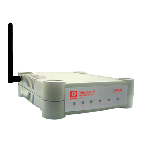
The Compex WP54G Wireless-G 54Mbps XR™ Access Point is a high-performance access point (AP) that is designed for enterprise public access applications. Embedded with the Atheros chipset, it boasts network robustness, stability and wider network coverage. Based on 802.11g, the access point supports high-speed data transmission of up to 54Mbps in the 2.4GHz frequency... -
Page 13: Chapter 1: Product Overview
• • The Compex unique Wireless Pseudo VLAN technology is a feature that allows wireless clients to be segmented individually or into workgroups, thus blocking access to another user’s/group’s PCs, and enhancing the privacy of the wireless clients. -
Page 14: Compex Wp54G Package
Protocol becomes unreachable, or if Spanning-Tree Protocol costs change, the spanning-tree algorithm reconfigures the spanning-tree topology and re-establishes the link by activating the standby path. The Compex WP54G 1a retail package contains the following items: 1 x Compex WP54G 1a •... -
Page 15: Access Point Mode
Product Overview This is the default mode of your access point. The Access Point mode enables you to bridge wireless clients to access the wired network infrastructure and to communicate with each other. In the example above, the wireless users will be able to access the file server connected to the switch through the access point in Access Point mode. -
Page 16: Access Point Client Mode
Product Overview In Access Point Client mode, the access point acts as a wireless client that can operate wirelessly with another access point to perform bridging between two Fast Ethernet networks. The Access Point client cannot communicate directly with any other wireless device. In the example above, the workgroup PCs will be able to access the printer connected to the access point in Access Point Client mode. -
Page 17: Point To Point Mode
In Point to Point mode, the access point allows point-to-point communication between different buildings. It enables you to bridge wireless clients that are kilometres apart ( eg. within 100 metres between two buildings ) while unifying the networks. In the example above, you may configure two access points (AP) to perform transparent bridging between two buildings... -
Page 18: Point To Multiple Point Mode
In Point to Multiple Point mode, this mode is similar to that of the Point to Point mode. But the access point located at one facility is able to connect to up to 15 access points (AP) installed in any direction from that facility (that is, 0 degree to 360 degrees ). -
Page 19: Wireless Routing Client Mode
An application of this mode would be for the Ethernet port of the Wireless Routing Client to be used for connection with other devices on the network while access Internet would achieved through wireless communication with wireless ISP. The above illustration describes how this mode operates. -
Page 20: Gateway Mode
Or put it more simply, Broadband Internet sharing in a wireless network! Since the access point supports several types of broadband connections, the first step in setting up the access point as a Broadband Internet Gateway is to identify the type of broadband Internet access you are subscribed to. Static IP address Use this type of connection if you have subscribed to a fixed IP address or to a range of fixed IP addresses from your Internet Service Provider. - Page 21 Product Overview For instance: If you are in Germany which uses T-1 connection or If you are using SingNet Broadband or Pacific Internet Broadband in Singapore. PPTP Select this type of connection if you are using ADSL services in a country utilising PPTP connection and authentication.
-
Page 22: Setup Requirements
The access point can be powered using either the power adapter provided or the Compex PoE Injector. The installation process for both options is described below. Connect the external antenna to the SMA connector of the access point. -
Page 23: Chapter 2: Hardware Installation
Hardware Installation Attach the power adapter to the main electrical supply, and connect the power plug into the socket of the access point. Turn ON the power supply and power ON your PC. Notice that the LEDs: Power and Port 1 or 2 (depending on which port you have connected the RJ45 Ethernet cable to) have lighted up. -
Page 24: Option Two: Using Compex Poe To Supply Power To Wp54G
(PoE) kit. The PoE accessory supplies operational power to the wireless AP via the Ethernet cable connection. Users who have already purchased the Compex PoE and who wish to use it to supply power to the access point may follow the installation procedures shown below: Connect the external antenna to the SMA connector of the access point. - Page 25 PoE Injector’s RJ45 Ethernet cable to your network device, such as to a switch or hub. Connect the power adapter supplied in the Compex PoE kit to the main electrical supply and the power plug into the socket of the injector.
- Page 26 Hardware Installation Now, turn on your power supply. Notice that the LEDs: Power and Port 1 or 2 (depending on which port you have connected the PoE injector to) have lighted up. This indicates that the access point is receiving power through the PoE Injector and that connection between your access point and your PC or other network device has been established.
-
Page 27: Chapter 3: Access To Web-Based Interface
2 to 254, so that it is in the same subnet as Access point. Compex has developed a powerful uConfig utility that has been designed to give you direct access to the Web interface. Insert the Product CD into your CD-ROM drive. The CD will run automatically. - Page 28 Access to Web-based Interface When the utility has been installed, double-click on the icon. The following screen will appear, click on the button to proceed. Select in the section and click on button. To retrieve and display the latest device(s), click on the button.
- Page 29 Access to Web-based Interface Do not exit the uConfig program while accessing to the web-based interface. This will disconnect you from the device. Click on the button to proceed. At the login page, press the button to enter the configuration page. The default password is “password”.
- Page 30 Access to Web-based Interface You will then reach the home page of your access point’s web-based interface.
-
Page 31: Verify The Ip Address Of Compex Wp54G With Npfind
Follow the next steps to check the IP address of your access point. Insert the Product CD into the CD-ROM drive. It will automatically run. Click on and select program to run it. The screen will then display the IP address of the Compex device detected. -
Page 32: Manual Access To Web-Based Interface Via Internet Explorer
Access to Web-based Interface For this method, you need to assign an IP address to your PC so that it belongs to the same subnet as your access point. In this example, we are using Windows XP for illustration. For Windows 98/98SE/2000/NT/ME, kindly refer to Appendix II “TCP/IP Configuration”. - Page 33 Access to Web-based Interface Highlight and click on the button. Select the radio button for . Enter the IP Address and Subnet Mask as 192.168.168.x and 255.255.255.0, where x can be any number from 2 to 254, except 1. In this example, we are using 192.168.168.160 as the static IP Address.
- Page 34 Access to Web-based Interface Click on the button to close all windows. Next, in order to check if the IP address has been correctly assigned to your PC, go to menu, , select and type the command ipconfig/all. Your PC is now ready to configure your access point. Launch your Web browser.
- Page 35 Access to Web-based Interface Open the tab and in the section, disable all the option boxes. Click on the button to update the changes. At the bar, enter http://192.168.168.1 and press on your keyboard. At the login page, click on the button to enter the configuration pages.
- Page 36 Access to Web-based Interface You will then reach the home page of your access point’s Web interface.
-
Page 37: Chapter 4: Common Configuration
Common Configuration This chapter illustrates the following features, which are available in ALL the operating modes of your access point, unless stated otherwise. • • • • • • • • • • • • This section shows you how to customize the parameters of your access point to suit the needs of your network. -
Page 38: Setting Up Your Lan
Common Configuration You can opt to adjust the default values of your access point and customize them to your network settings. Click on from the menu. In the page, refer to the table below to replace the default settings of Access point with appropriate values to suit the needs of your network. - Page 39 Common Configuration This table describes the parameters that can be modified in the Management Port Setup page. Parameters Description IP Address When the DHCP server of the router is enabled (unless you set a different DHCP Gateway IP Address), this LAN IP Address would be allocated as the Default Gateway of the DHCP client.
- Page 40 Common Configuration Parameters Description DHCP Gateway IP Though usually, the DHCP server also acts as the Default Address Gateway of the DHCP client, the access point gives you the option to define a different DHCP Gateway IP Address, which will be allocated as the Default Gateway of the DHCP client.
-
Page 41: To View The Active Dhcp Leases
Common Configuration The following will guide you to a page display of the active IP address leases that have been allocated by the built-in DHCP server of Access point. Click on from the menu. Go to the section, click on the button. -
Page 42: To Reserve Specific Ip Addresses For Predetermined Dhcp Clients
Common Configuration Making an IP address reservation lets you inform the DHCP server to exclude that specific address from the pool of free IP addresses it draws on for dynamic IP address allocation. For instance, if you set up a publicly accessible FTP/HTTP server within your private LAN, while that server would require a fixed IP address, you would still want the DHCP server to dynamically allocate IP addresses to the rest of the PCs on the LAN. - Page 43 Common Configuration Fill in: The host portion of the IP Address to reserve. The Hardware Address, in pairs of two hex values Press the button to make your new entry effective. page will then be refreshed to illustrate the currently reserved IP addresses.
- Page 44 Common Configuration If you do not need the DHCP server to reserve an IP address anymore, you can delete the DHCP Server Reservation. Click on the reserved IP address that you wish to delete, e.g. 192.168.168.20. Click on the button. table will then be refreshed to reflect your changes.
-
Page 45: Wlan Setup
Common Configuration This section shows how to perform the following functions: Basic: This function performs a basic setup of the wireless modes of operation: Access Point mode, Access Point Client mode and other operating modes. Security: This function performs data encryption and protection for the access point. Kindly refer to Chapter 5 on WLAN Security for details. -
Page 46: To Configure The Basic Setup Of The Wireless Mode
Common Configuration The following will guide you to configure the basic setup of the wireless mode you have selected. Click on from the menu. You will see the sub- menus expanded under . Click on The default operating mode of Access point is the Access Point mode. If you wish to change the current mode of your access point, click on , select your and click on the... - Page 47 Common Configuration Enter the parameters in their respective fields, click on the button and reboot your device to let your changes take effect. Note that the page for the Client mode is different from that of the Access Point mode. If you wish to set the access point in the mode, click on to select...
- Page 48 Common Configuration If you wish to set the access point in the mode, click on to select , and then you will see the page below. To create a new peer MAC, click on the button. The page will appear. ( Please take note that PtMP stands for Point to Multiple Point ). Click on , and then you are prompted to key in...
- Page 49 Common Configuration This table describes the parameters that can be modified in the page. Parameters Description The Current Mode The default operating mode of the access point is the Access Point mode. The access point can operate in 6 modes: Access Point •...
- Page 50 Common Configuration • • This mode supports wireless-G clients that offer transmission rates of up to 54Mbps in the 2.4GHz frequency band. Peer Mac ( Only in This mode can support more than one access point. This Point-to-Point feature allows you to create a new peer MAC for mode ) another access point so that the router operating in the access point mode can connect to another access...
- Page 51 Common Configuration In the page, click on the button. provides a list of the neighbouring access points detected, (channels), (Authentication), (Algorithm) used, and the strength of the received.
- Page 52 Common Configuration To connect the WP54G-client to one of the access points detected: Select the radio button corresponding to the access point you want to connect to. Click on the button to effect the change and return to the setup page.
- Page 53 Common Configuration NOTE The purpose of using Site Survey is to scan and display all access points based on the current security setting of your access point. For instance, the following information supplied by the Site Survey according to the security setting is explained: If the security mode is set to None or WEP, the scan will show •...
- Page 54 Common Configuration To view the connection status when WP54G-client is linked to another access point, click on the button. table illustrates the following data: This table describes the parameters that can be viewed from the page. Parameters Description State Refers to the MAC address of the BSS (AP to which the WP54G-client is connected).
-
Page 55: To Configure The Security Setup Of The Wireless Mode
Common Configuration Kindly refer to Chapter 5 on WLAN Security for details on setting the different security modes of the access point. The following will guide you to configure the advanced setup of the wireless mode you have selected. Click on from the menu to expand into the four sub-menus. - Page 56 Common Configuration This table describes the parameters that can be modified in the page. Parameters Description Beacon Interval The Beacon Interval is the amount of time between (Only in Access beacon transmissions. A beacon is a guidance signal Point mode) sent by the access point to announce its presence to other devices in the network.
-
Page 57: Statistics
Common Configuration For details on how to configure Wireless Pseudo VLAN, WDS and Long Distance Parameters, kindly refer to Chapter 6 on Wireless Extended Features. NOTE The values illustrated in the examples are suggested values for their respective parameters. The following shows you the information on the wireless device that is connected to the WLAN. - Page 58 Common Configuration To check the details on individual wireless client, click on the MAC Address in the WLAN Station List. The following screen will show the statistics of the selected wireless client.
- Page 59 Common Configuration Click on from the menu. You will see the sub- menus expanded under . Click on mode, you are not allowed to view other wireless clients’ statistics. To view other wireless clients information, you need to change to Access Point mode.
- Page 60 Common Configuration Click on from the menu. You will see the sub- menus expanded under . Click on mode, you are not allowed to view other wireless clients’ statistics. To view other wireless clients information, you need to change to Access Point mode.
- Page 61 Common Configuration Click on from the menu. You will see the sub- menus expanded under . Click on mode, you are not allowed to view other wireless clients’ statistics. To view other wireless clients information, you need to change to Access Point mode.
- Page 62 Common Configuration Click on from the menu. You will see the sub- menus expanded under . Click on mode, you are not allowed to view other wireless clients’ statistics. To view other wireless clients information, you need to change to Access Point mode.
- Page 63 Common Configuration Click on from the menu. You will see the sub- menus expanded under . Click on mode, you are not allowed to view other wireless clients’ statistics. To view other wireless clients information, you need to change to Access Point mode.
-
Page 64: Wan Setup
Common Configuration A correct WAN Setup allows you to successfully share your Internet connection among the wired and wireless clients of the access point. To do so, you need to identify the type of broadband Internet access you are subscribed to. If you are using : Cable Internet where your ISP dynamically assigns a WAN IP address to you, •... - Page 65 Common Configuration On the screen that follows, verify that the reads in red colour. Otherwise, click on the button. Step 3: Simply select and hit the button. Please remember to click under and hit button to let the settings take effect. Note: There are exceptional cases where additional configuration is required before an IP address will be allocated by your ISP to the access point.
- Page 66 Common Configuration Therefore, if this is the case, refer to your ISP for the correct DHCP Client ID to be set and follow steps 6 - 7 to accomplish the setup. Steps 4 - 5 are for those who need to clone their Ethernet adapter’s MAC address.
- Page 67 Common Configuration Step 7: On the following screen, key in the your ISP assigned DHCP Client ID as (You may also like to key in a preferred person and the the access point). Click the button to complete. Please remember to click under and hit button to let the settings...
- Page 68 Common Configuration WAN Setup - Cable Internet with Static IP Assignment If you have an ISP that leases a static WAN IP for your subscription, you will need to configure your access point’s WAN type accordingly. For example, if the ISP provided you with the following setup information, you can set up your WAN as described below: IP Address...
- Page 69 Common Configuration WAN Setup - ADSL Internet using PPP over Ethernet (PPPoE) If you subscribe to an ADSL service using PPP over Ethernet (PPPoE) authentication, you can set up your access point’s WAN type as follows. For example, you may configure an account whose username is ‘guest’ as described below: Step 1: Under...
- Page 70 Common Configuration setting is associated with the option, allowing you to specify the value (in seconds) after which the access point will disconnect from the ISP after the last Internet activity. A value of “0” will disable idle timeout. is associated with the option and specifies the maximum time the access point will wait before re-attempting to connect with your ISP.
- Page 71 Common Configuration button to let the settings take effect. setting allows you to specify the value (in seconds) after which the access point will disconnect from the ISP after the last Internet activity. A value of “0” will disable idle timeout.
-
Page 72: Snmp Setup
Common Configuration Simple Network Management Protocol (SNMP) is a set of communication protocols that separates the management architecture from the architecture of the hardware devices. Step 1: Click on from the menu. Step 2: Select from the drop-down list. The default is set to public while the default is private. -
Page 73: Stp Setup
Common Configuration Spanning Tree Protocol (STP) is a link management protocol that helps to prevent undesirable loops occurs in the network. For an Ethernet network to function properly, only one active path can exist between two stations. If a loop exists in the network topology, duplication of messages will occur and this might confuse the forwarding algorithm and allow duplicate frames to be forwarded. - Page 74 Common Configuration In short, the main purpose of activating STP is to prevent looping when you have redundant paths in the network. Without activating STP, redundant topology will cause broadcast storming. To establish path redundancy, STP creates a tree that spans all of the devices in an extended network, forcing redundant paths into a standby, or blocked, state, but establishing the redundant links as a backup in case the active link should fail.
- Page 75 Common Configuration The path with the smallest cost will be used and extra redundant paths will be disabled. To explain the effect of STP & Pseudo VLAN on the wireless clients, we will compare 3 separate scenarios. Scenario #1 – (No STP, No Pseudo VLAN) Referring to the illustration below, if the Spanning Tree Protocol (STP) and Pseudo VLAN are not implemented in a network, all clients (Notebook#1, #2, #3 &...
- Page 76 Common Configuration Scenario #2 – (With STP, No Pseudo VLAN) When STP is enabled, extra redundant network paths between APs will be disabled, hence preventing multiple active network paths in-between any two APs. If one of the APs is down, the STP algorithm will reactivate one of the redundant paths so that the network connection will not be lost.
- Page 77 Common Configuration Scenario #3 – (With STP and Pseudo VLAN) In this example, both STP and Pseudo VLAN Per Node are implemented in this network. When Pseudo VLAN Per Node is activated, the wireless users will be unable to access one another. Click on from the menu...
-
Page 78: Mac Filtering
Common Configuration MAC Filtering acts as a security measure by controlling the users accessing to the network through their MAC address. You can either keep a list of MAC address corresponding to users who are allowed to access the network or to keep a list of MAC address corresponding to users who are forbidden from network access. - Page 79 Common Configuration In the field, enter the wireless MAC address of the client, in the format xx-xx-xx-xx-xx-xx, where x can take any value in the range 0-9 or a-f. After that, you can enter the text in the field to describe the you just added.
- Page 80 Common Configuration Click on the button to update the changes. NOTE When Mac Filtering is enabled with the Allow PCs listed to access network policy, the Mac Address list cannot be empty. Follow the procedures mentioned in Step 2 to Step 3. Click on the in the table as shown below.
- Page 81 Common Configuration From the page, Click on the button to remove the MAC address, or Click on the button after you have edited the entry.
-
Page 82: Chapter 5: Wlan Security
This section illustrates how to make your WLAN more secure. All the nodes in your network MUST share the same wireless settings to be able to communicate. We will illustrate how to configure each type of security mode individually. To start with, follow the common preliminary steps described below to select the most appropriate security approach for protecting your wireless communications. -
Page 83: How To Set Up Wep
WLAN Security The guidelines below will help you to set up your access point for using WEP. At the WEP Setup page, Specify the , by selecting either: • • • • Select the from the pull down menu: • •... -
Page 84: How To Set Up Wpa-Psk/Wpa2-Psk/Wpa-Psk-Auto (Only Available In Access Point Mode)
WLAN Security Select the of each encryption key: • • 10 hexadecimal or 5 ASCII Text • • 26 hexadecimal or 13 ASCII Text To clear the values that you had entered in the field, click on the button. Click on the button and reboot your access point. - Page 85 WLAN Security Specify the , by selecting either: • • • • Fill in the (Pre-Shared network Key): If you are using the format, your entry can consist of a minimum of 8 alphanumeric characters or a maximum of 63 alphanumeric characters. Otherwise, when using the format, your entry MUST consist of 64 hexadecimal characters.
-
Page 86: How To Set Up 802.1X/Radius (Only Available In Access Point Mode)
WLAN Security Press the button and reboot your system, after which your settings will become effective. The guidelines below will help you to set up the access point for using 802.1x/RADIUS. At the IEEE 802.1x Setup page, Key in the IP address of the in your WLAN. - Page 87 WLAN Security By default, the value for number is . You can leave this value as it is. This value must be set to be the same as the one in the RADIUS server. Enter the in the field provided. By default, the is set as seconds.
-
Page 88: How To Set Up Wpa Eap/Wpa2-Eap/Wpa-Eap-Auto (Only Access Point Mode Supports Wpa2-Eap And Wpa-Eap-Auto)
The guidelines below will help you to set up the access point for using WPA-EAP. Please follow the steps below if you have selected the WPA or WPA1-EAP, WPA2-EAP or WPA-EAP-AUTO. At the page, Key in the IP address of the in your WLAN. - Page 89 WLAN Security By default, the value for . You can leave this value as it is. This value must be set to be the same as the one in the RADIUS server. Enter the used to validate client-server RADIUS communications. Select the of each encryption key: •...
- Page 90 WLAN Security Enter the This is the length of time after which the access point will automatically generate a new shared key to secure multicast/broadcast traffic among all stations that are communicating with it. By default, the value is 600 seconds. Press the button and reboot your system, after which your settings will become effective.
-
Page 91: Chapter 6: Wireless Extended Features
When operating in the Access Point mode, Access point allows you to define Wireless Pseudo VLAN Per Node and Wireless Pseudo VLAN Per Group. To learn more about Compex’s exclusive Wireless Pseudo VLAN, please refer to the white paper available online at www.cpx.com or www.compex.com.sg. -
Page 92: Wireless Pseudo Vlan Per Node
Wireless Extended Features When implemented, this mode isolates each wireless client into its own pseudo VLAN. Wireless clients can therefore access resources on the wired network but are unable to see each other or access each other’s data. - Page 93 Wireless Extended Features The following steps demonstrate how to set up a Wireless Pseudo VLAN per Node. From under Configuration, click on , which shows the page. Go to the section, and click on the button. function is disabled by default. Click on the button to make your selection of the type of Pseudo VLAN to implement.
- Page 94 Wireless Extended Features Select the radio button and click on the button. The Wireless Pseudo VLAN has configured as Per node.
-
Page 95: Wireless Pseudo Vlan Per Group
Wireless Extended Features The access point can configure up to 32 ‘groups’ of wireless clients identified by their MAC address. Whenever a wireless client requests network access, the access point will first verify whether its MAC address is present in any of the Pseudo VLAN groups. - Page 96 Wireless Extended Features The following steps demonstrate how to set up Wireless Pseudo VLAN Groups. From the page, select and click on the button. Click on the button to create a client in the Wireless Pseudo VLAN group.
- Page 97 Wireless Extended Features Select a group number from the drop-down list. Fill in the field with the MAC address of the client in the format , where x is any value within the range 0-9 or a-f. Click on the button to update the changes.
- Page 98 Wireless Extended Features Follow the procedures mentioned in Steps 3-5. You can create up to 32 members per Wireless Pseudo VLAN group. Click on the in the table as shown below. From the page, Click on the button to remove the client from the group, or Click on the button after you had edited the entry.
-
Page 99: Wireless Setup - The Wireless Distributed System (Wds)
Wireless Extended Features (Only in Access Point mode) A wireless distribution system links up several access points, creating a wider network in which mobile users can roam while still staying connected to the available network resources. In a WDS, the access point can drive a cell of wired and wireless clients while at the same time, connecting to other access points. - Page 100 Wireless Extended Features Chain Configuration WDS A chain configuration WDS spans an area in length, for instance a long corridor. Satellite access points are chained together starting from a root access point. The access point at either end of the chain will have only one WDS link enabled, while the access points in the middle will have two WDS links configured to associate with the neighboring Access point upward and downward in the chain.
- Page 101 Wireless Extended Features The following steps will guide you in setting up WDS in your access point. From under Configuration, click on , which shows the page. Go to the section, and click on the button. As illustrated on the , the feature is disabled by default.
- Page 102 Wireless Extended Features From the page, select and click on the button. Click on the button to create a MAC address of a client. Fill up the field with the wireless MAC address of the device to include in your WDS, using the format xx-xx-xx-xx-xx-xx, where x can take any hexadecimal value 0-9 or a-f.
- Page 103 Wireless Extended Features From the page, notice that the MAC Address has been added to the table as shown below. NOTE To configure WDS, all your access points must use the same channel and security mode and both access points at opposite ends of a WDS link must have each other’s wireless MAC address Follow the procedures mentioned in Step 5 to Step 7.
- Page 104 Wireless Extended Features Click on the in the table as shown below. From the page, Click on the button to remove the client from the WDS, or Click on the button after you have edited the entry.
-
Page 105: Long Distance Parameters
Wireless Extended Features This setup allows the access point to calculate and display suggested values for certain parameters to use to ensure that wireless communication takes place efficiently and effortlessly between physically distant APs. The following steps demonstrate how to configure the Long Distance Parameters. From under Configuration, click on , which shows the... - Page 106 Wireless Extended Features As illustrated on the Setup page, the feature is disabled by default. Select from the pull down menu. The access point can automatically calculate the values of the parameters to input based on the distance between your access point and the other wireless device.
- Page 107 Wireless Extended Features You can enter the parameters according to the recommended values in the pop-up window, click on the button to update the changes. This table describes the parameters that can be modified in the Long Distance Parameters page. Parameters Description Outdoor...
-
Page 108: Chapter 7: Advanced Configuration
Advanced Configuration The access point allows the network administrator to add a static routing entry into its routing table so that the access point can re-route IP packets to another network access point. This feature is very useful for a network with more than one access point. -
Page 109: To Configure Static Routing Of Compex Wp54G
Advanced Configuration In this network, the main office of subnet 192.168.168.0 contains two routers: the office is connected to the Internet via the access point (192.168.168.1) and to the remote office via NetPassage 16A (192.168.168.254). The remote office resides on a subnet 192.168.100.0. You may add a static routing entry into the access point’s routing tables so that IP packets from the clients in the main office with a destination IP address of 192.168.100.X (where X is any number from 2 to 254) will be routed to the... - Page 110 Advanced Configuration When the entry is added, it is reflected in the The basic purpose of NAT is to share a single public IP address when there are multiple PCs in the private network by using different TCP ports to identify requests coming from different PCs.
-
Page 111: Nat (Only Supported By Wireless Routing Client And Gateway)
Advanced Configuration Important: Do NOT disable NAT unless absolutely necessary. Disabling NAT will disable broadband Internet sharing effectively. Having gone through the NAT Technology Primer on the Product CD, you would now have a good understanding of how DMZ works to make a specific PC in an NAT-enabled network directly accessible from the Internet. - Page 112 Advanced Configuration address for the PC we wish to place within the DMZ : 192.168.168.55 (Enter as the and it will disable DMZ). Remember click button. You may wish to set up a DMZ host if you intend to use a special- purpose Internet Service such as an online game for which no i NOTE When you enable DMZ, the Static IP Address configuration is...
-
Page 113: To Configure Virtual Servers Based On Port Forwarding
Advanced Configuration Virtual Server based on Port Forwarding is implemented to forward Internet requests arriving at the access point’s WAN interface, based on their TCP ports, to specific PCs in the private network. If you require more information on this function, please refer to the NAT Technology Primer on the Product CD. - Page 114 Advanced Configuration Step 4: On the following screen, you can set up a Virtual Server for a type by selecting from a drop-down menu OR you can define a For a more detailed explanation, please refer to the NAT Technology Primer found on the Product CD.
-
Page 115: To Configure Virtual Servers Based On Ip Forwarding
Advanced Configuration As an example, if you want to set up a web server on a PC with IP address of 192.168.168.55, select HTTP as enter as the . Click on the button. You will see the entry reflected as on the right. - Page 116 Advanced Configuration 192.168.168.55. Step 4: Click the button to continue. Step 5: page will reflect your new addition. NOTE For step 3 above, please ensure that you have subscribed to the Public IP Address you intend to forward from.
-
Page 117: Remote Management
Advanced Configuration The advanced network administrator will be delighted to know that remote management is supported on the access point. With this feature enabled, you will be able to access the access point’s web-based configuration pages from anywhere on the Internet and manage your home/office network remotely. Only two simple steps are required to set up remote management for the access point. -
Page 118: Parallel Broadband (Only Supported By Gateway)
Advanced Configuration The access point is equipped with the exclusive Parallel Broadband technology to provide scalable Internet bandwidth with Load Balancing and Fail-Over Redundancy. By installing multiple units of the access point cascaded using Parallel Broadband, you may balance the Internet traffic generated from your private network over multiple broadband connections - providing the network with aggregated bandwidth! In the event of a particular broadband connection failing, The access point in cascade will use the remaining functional... -
Page 119: To Enable Parallel Broadband On Compex Wp54G
Advanced Configuration To learn more about Parallel Broadband, please read the whitepaper at www.cpx.com or www.compex.com.sg. Before you begin, ensure that each of the access point within the network is properly configured to connect to its individual broadband Internet account. -
Page 120: Email Notification
Advanced Configuration Important: If you have only one unit of the access point, you DO NOT need to implement the Parallel Broadband feature for broadband Internet sharing. The access point provides this feature to notify you by email when there is a change in the WAN IP address that was supplied to you earlier. - Page 121 Advanced Configuration Email address of Receiver: • This is the email address of the receiver to whom the message would be sent. IP address of Email Server: • This is the IP address of the SMTP server through which the message would be sent out.
- Page 122 Advanced Configuration If you use a notebook for work at the office, it is probable that you also bring it home to connect to the Internet and retrieve emails or surf the web. Since it is most likely that your office’s and your home’s broadband-sharing network subnets are differently configured, you would have to struggle with reconfiguring your TCP/IP settings each time you use the notebook in a different place.
-
Page 123: Static Address Translation (Only Supported By Wireless Routing Client And Gateway)
Advanced Configuration Step 1: Under the command menu, click on Step 2: You may then choose to Static Address Translation here, followed by clicking the button. (Note: SAT is disabled by default) -
Page 124: Dns Redirection (Only Supported By Wireless Routing Client And Gateway)
Advanced Configuration When you enter a URL in your Internet browser, the browser requests for a name-to-IP address translation from the Domain Name System (DNS) servers to be able to locate the web server hosting the website you want to access. The DNS server, in turn, looks for the answer in its local cache and if an appropriate entry is found, sends back this cached IP address to the browser. - Page 125 Advanced Configuration NOTE For Internet access, please do NOT leave the DNS Server field of the PC’s TCP/IP Properties blank. Simply key in any legal IP address for it (e.g. 10.10.10.10) even though you do not have the exact DNS IP address.
-
Page 126: To Enable/Disable Dns Redirection
Advanced Configuration Step 1: Under the command menu, click on Step 2: Simply choose Step 3: Complete the setup by clicking the button. It is difficult to remember the IP addresses used by computers to communicate on the Internet. It gets even more complicated when ISPs change your public IP address regularly, as is the case when the Internet connection type is Dynamic IP or PPPoE with Dynamic IP. -
Page 127: To Enable/Disable Dynamic Dns Setup
Advanced Configuration If someone types in your address: MyName.Domain.com into their web browser, this request would go to the DDNS provider which would then re-direct that request to your computer, no matter what IP address it has been currently assigned by your ISP. Step 1: Under the command menu, click on... - Page 128 Advanced Configuration To add a new Dynamic DNS to the list, click on the Add button and you will see the page appear. There are two default providers which you can use. The following parameters are explained below: Choice : •...
- Page 129 Advanced Configuration (Optional) enable wildcard service, your hostname would allowed multiple identities. example, register: users looking for www.mydomain.2mydns.net ftp.mydomain.2mydns.net can still reach your hostname. Step 5: (Optional) In the Mail Exchanger field, enter the Static WAN IP address mail server configured to handle email for your domain.
- Page 130 Advanced Configuration...
- Page 131 Advanced Configuration To select DtDNS as DDNS Service Provider Step 1: Under the column in the table of check the radio button next to the . Then click on the button to proceed. Step 2: Enter your Step 3: Select to let the DtDNS server learn your current WAN IP address.
-
Page 132: Chapter 8: Security Configuration
This chapter describes the security configuration mainly found in the Wireless Routing Client and Gateway modes. As part of the comprehensive security package found on the access point, you may perform IP packet filtering to selectively allow/disallow certain applications from connecting to the Internet. Step 1: Under the command menu, click on... -
Page 133: Security Configuration
Security Configuration Step 4: Click on the button and you will be able to define the details of your from the screen on the right. Enter Rule Name for this new 4a). packet filtering rule. example, BlockCS 4b). From the IP Address drop down list, select whether to... - Page 134 Security Configuration down list, select either: Range of TCP ports In this case, you will have to define (From) which port (To) which port, your rule applies. Single TCP port Here, you need only specify the source port in the (From) field.
- Page 135 Security Configuration MM, any value from 00 to 59. time Here, you may leave both (From) (To) fields blank. Step 5: Click on the button to make the new rule effective. table will then be updated. Step 6: In this example, let us say we would like block...
-
Page 136: Url Filtering
Security Configuration The access point supports URL Filtering which allows you to easily set up rules to block objectionable web sites from your LAN users. Step 1: Under the command menu, click on Step 2: You may now define the by clicking the button. -
Page 137: Firewall Configuration
To learn more about SPI firewall, read our whitepaper at www.cpx.com or at www.compex.com.sg. he following steps explain the configuration of Compex’s SPI firewall. As incorrect configuration to the firewall can result in undesirable network behavior, you are advised to carefully plan your firewall security rules. Step 1:... - Page 138 Security Configuration protocol can be recorded. The packet types that you have selected in the section will be displayed in the firewall log if they are detected by the firewall. This also applies to the section. Step 4: You may add more firewall rules for specific security purposes.
- Page 139 Security Configuration ICMP Packet Type Description Echo request Determines whether an IP node (a host or a router) is available on the network. Echo reply Replies to an ICMP echo request. Destination Informs the host that a datagram cannot unreachable be delivered.
- Page 140 Security Configuration range of IP addresses. Source Port You can control requests for using a specific application by entering its port number here. Users can either set a single port number or a range of port numbers. Destination Port This parameter determines the application from the specified destination port.
-
Page 141: Firewall Logs
Security Configuration When the access point’s SPI firewall is in operation, valuable traffic patterns in your network will be captured and stored into the Firewall Logs. From these logs, you can extract detailed information about the type of data traffic, the time, the source and destination address/port as well as the action taken by the SPI firewall. -
Page 142: Chapter 9: System Utilities
This feature lets you determine whether your access point can communicate (ping) with another network host. This feature is available only for the Wireless Routing Client and Gateway modes. Step 1: Select under the command menu. Step 2: Enter the IP address of the target host where the target host you want the access point to ping to. -
Page 143: System Identity
System Utilities If your network operates with several access points, you would find it useful to have a means of identifying each individual device. You can define the System Identity of your access point to be uniquely identifiable as follows: Click on from the menu. -
Page 144: Set System's Clock
System Utilities ’ ’ Click on ’ ’ from the menu. Select the appropriate time zone from the drop-down list. the Auto Time Setting (SNTP) radio button. stands for Simple Network Time Protocol and is used to synchronise computer clocks. Fill in the field and click on the button to effect the... -
Page 145: Firmware Upgrade
System Utilities Keep your access point updated with the latest capabilities by downloading its latest firmware revision from either of Compex’s corporate web sites at www.compex.com.sg or www.cpx.com before following the next steps. You can check the types and version of your firmware by clicking on About System from the HELP menu. - Page 146 System Utilities Follow the instructions given during the upgrading process. You need to reboot the system after the firmware upgrade. NOTE The firmware upgrade process must NOT be interrupted otherwise the device might become unusable.
-
Page 147: Backup Or Reset Settings
System Utilities You may choose to save the current configuration profile, to make a backup of it onto your hard disk, to restore an earlier profile saved on file or to reset the access point back to its default settings. Click on from the menu. - Page 148 System Utilities Click on from the menu. If you want to back up the current settings of your access point onto your hard disk drive, click on the button. Next, save your configuration file to your local disk.
- Page 149 System Utilities Click on from the menu. If you want to store back the settings that you had previously saved, click on … button. Proceed to the folder where you saved your … configuration file. Click on the button and the system will prompt you to reboot your device.
-
Page 150: Reboot System
System Utilities Most of the changes you make to the system’s settings require a system reboot before the new parameters can take effect. Click on from the menu. Click on the button. Wait for the system to reboot and the login page will be displayed. -
Page 151: Change Password
System Utilities It is recommended that you change the default login password, which is case sensitive and is set by default, to password. Click on from the menu. Key in the . The factory default is password. Enter the in the field as well as in the field. -
Page 152: Logout
System Utilities To exit the Web interface, follow the next few steps. Click on from the menu. Click the button to access your access point’s configuration interface again. -
Page 153: Using The Help Menu
Click on from the menu. The access point is a feature-packed device. If you require further information than provided in the manual or data sheet, please contact one of Compex’s Technical Support Centres by mail, email, fax or telephone. -
Page 154: About System
System Utilities The About System page displays a summary of your system configuration information. Support technicians might require specific information about your system data when they are troubleshooting your configuration. You can use the information displayed in this page to quickly find the data they need to resolve your system problem. -
Page 155: Appendix I: Firmware Recovery
Power the access point on, and then start up your computer. You are recommended to set your computer’s IP address to 192.168.168.100 and its network mask to 255.255.255.0. Insert the Compex WP54G Product CD into the CD drive of your computer. -
Page 156: Firmware Recovery
Firmware Recovery From the Start menu, click Run and type cmd. When the command prompt window appears, type in the following command: X:\recovery\TFTP -i 192.168.168.1 PUT image_name.IMG, where refers to your CD drive and image_name.IMG to the firmware filename found in the Recovery folder of the Product CD. -
Page 157: For Windows 95/98/98Se/Me/Nt
Once the hardware has been set up, you need to assign an IP address to your PC so that it will be in the same subnet as the access point. By default, the access point’s IP address is 192.168.168.1; and its subnet mask is 255.255.255.0. You need to configure your PC’s IP address to 192.168.168.xxx;... -
Page 158: Appendix Ii: Tcp/Ip Configuration
TCP/IP Configuration Select radio button Specify an IP address. Enter the IP Address and Subnet Mask 192.168.168.X 255.255.255.0, where X can be any number from 2 to 254, except for 1. In this example, we are using 192.168.168.160 as the static IP Address. - Page 159 TCP/IP Configuration menu, select Run, and enter the command winipcfg. Select your respective Ethernet Adapter from the drop down list and click OK. Now, your PC is now ready to communicate with your access point.
-
Page 160: For Windows Xp/2000
Go to your desktop, right-click on My Network Places icon and select Properties. Go to your network adapter icon, right click and select to Properties. Highlight Internet Protocol (TCP/IP) and click on Properties button. - Page 161 TCP/IP Configuration Select the radio button for Use the following IP address. Enter the IP Address Subnet Mask 192.168.168.X 255.255.255.0, where Xcan be any number from 2 to 254, except for 1. In this example, we are using 192.168.168.160 as the static IP Address.
- Page 162 & & Front View of Access Point Name Description Steady Blue The device is powered up. (Power) No power is supplied to the device. Flashing Green This indicates the flash during the power-up. The LED will goes off (Diagnostic) when the diagnostic is passed. Steady Green WAN connection is established.
-
Page 163: Appendix Iii: Panel Views & Descriptions
Panel Views & Descriptions Link/Act LED) Flashing Green Activity is detected in the wireless network. Steady Green Connection has been established (Port & between device LEDs) network. Flashing Green Activity is detected in the network. No network connection. Back View of Access Point Name Description External Antenna... - Page 164 Panel Views & Descriptions Bottom View of Access Point Name Description Reset Push button To reboot, press once. To reset password, press and hold the button for 5 seconds. The DIAG light will flash fast for about 5 flashes/sec before releasing the button. To restore the factory default settings, press and hold the button for more than 10 seconds.
-
Page 165: Appendix Iv: Technical Specifications
Safety • FCC Part 15 SubPart B and SubPart C (for Electromagnetic wireless module) Conformance • EN 300 328-2 • EMC CE EN 301 489 (EN300 826) • EN 55022 (CISPR 22)/EN 55024 Class B • EN 61000-3-2 • EN61000-3-3 •... -
Page 166: Technical Specifications
• HTTP Web Management • SNMP - SNMP (RFC1157) - SNMP (RFC1213) Built-in DHCP Server DHCP Reservation By MAC address Configuration Backup & Restore Firmware Upgrade Power Requirements Using Power Adapter: Output 9VDC (localized to country of sale) Using PoE: Compex PoE Injector... - Page 167 Technical Specifications Operating Temp: -15ºC to 70ºC Storage Temp: 5% to 95% RH Operating Humidity: Humidity (RH – Relative Humidity): Physical Dimensions 145mm x 132mm x 41mm (H x W x D)
Need help?
Do you have a question about the wp54g 1a and is the answer not in the manual?
Questions and answers