Advertisement
Quick Links
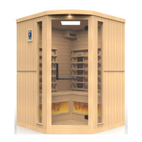
GDI-8035-02
3 Person Sauna
OWNER'S MANUAL
FOR CARBON MODEL SAUNAS
INDOOR USE ONLY
120VAC 20AMP DEDICATED CIRCUIT REQUIRED
Carefully and thoroughly read this Owner's Manual before using/operating the
sauna. We recommend keeping this Owner's Manual for regular review and future
reference. Parts and accessories may vary and are subject to change.
1
Advertisement

Related Manuals for GoldenDesigns GDI-8035-02


Summary of Contents for GoldenDesigns GDI-8035-02
- Page 1 GDI-8035-02 3 Person Sauna OWNER’S MANUAL FOR CARBON MODEL SAUNAS INDOOR USE ONLY 120VAC 20AMP DEDICATED CIRCUIT REQUIRED Carefully and thoroughly read this Owner’s Manual before using/operating the sauna. We recommend keeping this Owner’s Manual for regular review and future...
-
Page 2: Table Of Contents
TABLE OF CONTENTS Packing List Visual Assembly Diagram Parts Description Assembly Instructions Operating the Sauna Tips for Using Your Sauna Safety Instructions Safeguards for Your Sauna Troubleshooting Guide Warranty Warranty Card WARNING: Visually inspect all heaters before assembly to make sure they are not damaged. - Page 3 What Are Infrared Rays? Infrared is the band of light we perceive as heat. We cannot see this band of light with the naked eye, but we can feel this type of light in the form of heat. Our sun produces most of its energy output in the infrared segment of the spectrum.
- Page 4 EMF Levels from Common Homes Sources After many years and numerous studies on EMF exposure, no government body including the Occupational Safety and Health Administration (OSHA) have established permissible exposure limits (PEL). Currently, there is no consensus on the potential health hazard from any exposure to EMF.
- Page 5 HOW IT WORKS Infrared Saunas differ from traditional saunas in that they use infrared radiant energy to directly penetrate into the body's tissue to produce perspiration. Traditional saunas use steam to heat the air inside the sauna, which then heats your body until you begin to perspire.
-
Page 6: Visual Assembly Diagram
*PLEASE READ INSTRUCTIONS BEFORE ASSEMBLY* Visual Assembly Diagram GDI-8035-02 *The above assembly diagram i s for a quick reference visual guide only. All sauna models are not shown. Parts and accessories may vary and are subject to change. Backrests are sold separately. -
Page 7: Parts Description
PARTS DESCRIPTION GDI-8035-02 NOTE: The pictures and diagrams shown within this owner’s manual are representations of this model. Actual model may vary. Design and Construction are subject to change. Backrests are sold separately. - Page 8 Power Supply (Control Box) The POWER SUPPLY is the control center of the sauna room. It is installed on the topside of the ROOF PANEL and has inputs/outputs connected to it. (see Figure 1) Figure 1 POWER IN - main power of the sauna room HT1, HT2, HT3, HT4, HT5, HT6 –...
- Page 9 HT1, HT2, HT3, HT4, HT5, HT6 – Heater cords connect the heat emitters to the POWER SUPPLY at these ports (HT5 & HT6 are not used on most models) Lighting – Connects the interior lighting to the POWER SUPPLY at this port LampRoof –...
- Page 10 A. Floor Panel When the floor panel faces upward, you will find that the edges are raised. The wall panels will seat inside of the raised edge. The front of the floor panel is indicated below. Please note the correct position before you began assembling the wall panels.
-
Page 11: Assembly Instructions
C. Rear Panels If you are facing the front of the sauna, the rear panel with the heat emitter panels on the interior will be the inside of the sauna room. (see Figure 7) Figure 7 Assembly Instructions A. Choose a good location to assemble the sauna 1. - Page 12 Figure 8 Front C. Installing the FRONT PANEL, LEFT SIDE PANEL, and RIGHT SIDE PANEL 1. Determine the correct placement of the FRONT PANEL in the figure diagram below. Insert the FRONT PANEL onto the FLOOR PANEL. Then place the LEFT SIDE PANEL onto the FLOOR PANEL next to the FRONT PANEL.
- Page 13 the LEFT SIDE REAR PANEL onto the FLOOR PANEL. The LEFT SIDE REAR PANEL will fit like a puzzle with the LEFT SIDE PANEL. Once they are inserted properly, you can buckle the two walls together. The RIGHT SIDE REAR PANEL will be a bit tight in installing. You will want to insert the bottom first onto the FLOOR PANEL and carefully work the top into place.
- Page 14 Figure 12 E. Installing the ROOF PANEL 1. The side with the slight curve is the front of the ROOF PANEL. The power supply box faces upward on the ROOF PANEL. 2. The edge nearest the power supply is the front of the ROOF PANEL. Be careful of the wires coming from the SIDE and REAR PANELS when you set the ROOF PANEL down onto the panels.
- Page 15 Figure 13 Figure 14 F. Installing the HIMALAYAN SALT BLOCK PANEL, BENCH EMITTER PANEL, and BENCHES 1. First, locate the FLOOR HEATER power cord. Connect the power cord into the wall outlet on the RIGHT SIDE REAR PANEL towards the back corner of the sauna room. (see Figure 15) 2.
- Page 16 downward and into position. Then slide the shorter of the two BENCHES into its position. Push the BENCHES all the way in until they touch the REAR PANELS and are secured in place. Make sure to install the BENCHES with the smooth and finished sides facing up and the predrilled holes at the rear.
- Page 17 G. Connecting the plugs on the ROOF PANEL 1. Connect the plugs according to their respective labels. (see Figure 21) 2. You will need to connect the right and left speaker, the MP3, the CTRL (Panel Control), and the CD/SIG (radio power). The CD/SIG will be connected once the radio is installed in step 9 below.
- Page 18 2. If your sauna comes with the optional shelf and/or aroma therapy dish, use the screws provided to mount the shelf and aroma therapy dish where indicated within the sauna room. (see Figure 25 and 26) Figure 25 Figure 26 I.
- Page 19 Figure 27 Figure 28 Figure 29 Figure 30 Figure 31 Figure 32...
-
Page 20: Operating The Sauna
J. Putting on the ROOF COVER (optional) 1. Place the ROOF COVER over the top of the sauna. Be cautious when pulling the power cord through the hole in the roof cover. Slide the antenna through the slot allotted. Gently place the ROOF COVER onto the ROOF PANEL. - Page 21 CAUTION: Exit Sauna Immediately If You Feel Dizzy, Sleepy, Or Any Discomfort. Control Panel Power On/Off: Press to control the main power of the sauna Power Indicator: Indicates the status of the sauna’s main power Work Start/Stop: Press to control the working functions of the sauna Work Indicator: Indicates the working status of the sauna Heat Indicator: Indicates the status of heating function...
- Page 22 You can use the up/down arrows to adjust the time. If you do choose to adjust the time, the control panel will flash and the emitters will stop generating heat. Once you set the time to the desired setting, then press the START/WORK button twice and the control panel will stop flashing and heat will began coming from the emitters once again.
-
Page 23: Tips For Using Your Sauna
10. Please Note: On average, it takes our model saunas approximately: *20 minutes to reach into 100 degrees Fahrenheit/38 degrees Celsius (with a Starting temperature above 70 degrees Fahrenheit/21 degrees Celsius) *25-30 mins to reach about 115-120 degrees Fahrenheit/46-49 degrees Celsius (depending on sauna model) *35-40 minutes to reach about 125-130 degrees Fahrenheit/52-54 degrees Celsius (depending on sauna model) -
Page 24: Safety Instructions
in boosting your immune system and decreasing the reproductive rate of the virus. 7. To help relieve sore and tense muscles, massage the affected areas during your sauna session. 8. To treat your ankles and feet more effectively, you can elevate them and move them close to one of the heat emitters to achieve a deep heating effect. - Page 25 8. Persons suffering from obesity or with a medical history of heart disease, low or high blood pressure, circulatory system problems, diabetes, or other medical conditions should consult with a medical physician prior to using the sauna. 9. Persons using medications should consult with a medical physician before using the sauna.
-
Page 26: Safeguards For Your Sauna
operation. If for any reason your sauna does not seem to be operating properly, discontinue use and contact Customer Service. Safeguards For Your Sauna 1. Do not install the sauna near water, near a bathtub (if water will splash on the sauna), near a shower (if water will splash on the sauna), in a wet basement, or near a swimming pool (if water will splash on the sauna). - Page 27 connected, including the cord to the heat emitter underneath the bench (if applicable). Go to the roof, and also check that the heat emitter cords are properly connected snug and tight to the cords on the roof and that those cords are properly plugged into the power supply (snug and tight).
- Page 28 cords are damaged. If the power supply is malfunctioning or power cords are damaged, then unplug the sauna immediately and contact the Customer Service. Solution: The control panel will not turn off, the power/work/or heat lights do not come on, or the temperature and timer buttons do not work means the control panel may have been damaged and will need to be replaced.
- Page 29 sauna room. Check both ends of this connection including at the power supply box. 2. Disconnect the "PANEL CONTROL" harnesses (both ends) and then reconnect making sure that the connection is snug and tight. 3. Also and while up on the roof, please located the temperature sensor wire.
- Page 30 make for a bad connection and cause an unusual amount of heat buildup. Loose connections can also cause sparking in the junction box that can result in arcing. You'll likely see burn marks around the terminals if this happens. You will need to consult with an electrician to replace the wall outlet.
- Page 31 9. Dedicated Power Outlet Solution: You have two options when it comes to a dedicate receptacle. You have a true dedicated line if the receptacle is the only receptacle on the line to the breaker in your electric panel box. You have a quasi-dedicated line if you have multiple receptacles on a line to the breaker in your electric panel box and you do not draw any power from the other receptacles when the sauna is in operation.
- Page 32 can use a towel to drape over your legs to trap the heat as it rises if your lower extremities feel a draft. 11. Intentional Rear Wall Warp Solution: The rear wall panel is intentionally warped as part of the sauna design.
- Page 33 Limited Lifetime Warranty 7 Year Limited Warranty: Golden Designs, Inc. under the Dynamic brand name and other brand names warranties the wood, structure, heating elements, and electronics against defects in material and workmanship for a period of 1 to 5 years from the original date of purchase.
- Page 34 Normal wear and tear or weathering Use of product not in accordance with instructions Worn out receptacle Surface cracks are not considered defects in material or workmanship, as they are normal characteristics of all woods. This includes minor cracks due to wood expansion and contraction.
-
Page 35: Warranty Card
WARRANTY CARD Congratulations on your purchase of an Infrared Sauna from Golden Designs, Inc. Please take the time to complete the following Warranty Card and mail it back to: Golden Designs, Inc. 3550 Jurupa Street, Unit B Ontario, CA 91761 Please include a copy of your sales receipt showing date of purchase as this will serve as proof of purchase.
Need help?
Do you have a question about the GDI-8035-02 and is the answer not in the manual?
Questions and answers