Advertisement
Quick Links
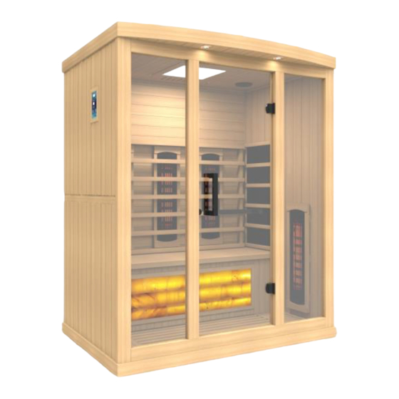
GDI-8030-02
3-Person Saunas
OWNER'S MANUAL
FOR CARBON MODEL SAUNAS
INDOOR USE ONLY
120VAC 20 AMP DEDICATED CIRCUIT REQUIRED
Carefully and thoroughly read this Owner's Manual before using/operating the
sauna. We recommend keeping this Owner's Manual for regular review and future
reference. Parts and accessories may vary and are subject to change.
1
Advertisement

Related Manuals for GoldenDesigns GDI-8030-02


Summary of Contents for GoldenDesigns GDI-8030-02
- Page 1 GDI-8030-02 3-Person Saunas OWNER’S MANUAL FOR CARBON MODEL SAUNAS INDOOR USE ONLY 120VAC 20 AMP DEDICATED CIRCUIT REQUIRED Carefully and thoroughly read this Owner’s Manual before using/operating the sauna. We recommend keeping this Owner’s Manual for regular review and future...
- Page 2 TABLE OF CONTENTS Packing List Visual Assembly Diagrams Parts Description Assembly Instructions Operating the Sauna Tips for Using Your Sauna Safety Instructions Safeguards for Your Sauna Troubleshooting Guide Warranty Warranty Card WARNING: Visually inspect all heaters before assembly to make sure they are not damaged.
- Page 3 What Are Infrared Rays? Infrared is the band of light we perceive as heat. We cannot see this band of light with the naked eye, but we can feel this type of light in the form of heat. Our sun produces most of its energy output in the infrared segment of the spectrum.
- Page 4 EMF Levels from Common Homes Sources After many years and numerous studies on EMF exposure, no government body including the Occupational Safety and Health Administration (OSHA) have established permissible exposure limits (PEL). Currently, there is no consensus on the potential health hazard from any exposure to EMF.
- Page 5 HOW IT WORKS Infrared Saunas differ from traditional saunas in that they use infrared radiant energy to directly penetrate into the body's tissue to produce perspiration. Traditional saunas use steam to heat the air inside the sauna, which then heats your body until you begin to perspire.
- Page 6 *PLEASE READ INSTRUCTIONS BEFORE ASSEMBLY* GDI-8030-02 *The above assembly diagram i s for a quick reference visual guide only. All sauna models are not shown. Parts and accessories may vary and are subject to change. Near Infrared Heaters and backrests are sold separately.
- Page 7 PARTS DESCRIPTION GDI-8030-02 NOTE: The pictures and diagrams shown within this owner’s manual are representations of this model. Actual model may vary. Design and Construction are subject to change. Backrests are sold separately.
- Page 8 Power Supply (Control Box) The POWER SUPPLY is the control center of the sauna room. It is installed on the topside of the ROOF PANEL and has inputs/outputs connected to it. (see Figure 1) Figure 1 POWER IN - main power of the sauna room HT1, HT2, HT3, HT4, HT5, HT6 –...
- Page 9 HT1, HT2, HT3, HT4, HT5, HT6 – Heater cords connect the heat emitters to the POWER SUPPLY at these ports (HT5 & HT6 are not used on most models) Lighting – Connects the interior lighting to the POWER SUPPLY at this port LampRoof –...
- Page 10 Side moldings may not be apparent on 2-person models. (see Figure 4) Floor Heater Cord Notch Cutouts Figure 4 Front V. Panel Descriptions For easier installation, please understand and distinguish the differences between each panel. A. Floor Panel When you place the FLOOR PANEL at its designated location, leave enough space so that you are able to move around the FLOOR PANEL in order to install the sauna wall panels.
- Page 11 the front glass door and stationary glass panels. (see Figure 6 and Figure Figure 6 Figure 6a C. Roof Panel The ROOF PANEL houses the power supply, speakers, MP3 AUX jack, and reading lamp. Once installed, all the wiring harnesses, plugs, and connections will sit on the exterior side of the roof panel.
- Page 12 B. Installing the FLOOR PANEL 1. Place the FLOOR PANEL on the floor. Make sure the front side of the FLOOR PANEL is facing the correct direction. Please note the heater cord coming out of the topside of the floor panel at the rear right. (see Panel Descriptions) (see Figure 7) Figure 7 Front of Sauna Room...
- Page 13 2. To install the DOOR HANDLE, first locate the DOOR HANDLE. It may need to be dismantled in order to install. Next, place the long handle section horizontally and install it on the glass door from the inside. You will need to secure the side of the long horizontal handle closest to the hinge side of the glass door by screwing it to the glass door.
- Page 14 Figure 11 E. Installing the HIMALAYAN SALT BLOCK PANEL and BENCH 1. Installing the HIMALAYAN SALT BLOCK PANEL can be done by sliding it downward between the two side wall panels. (see Figure 12) 2. Plug in the FLOOR HEATER cord and light connection (for the HIMALAYAN SALT BLOCK illumination) into the corresponding wall outlets.
- Page 15 F. Installing the ROOF PANEL 1. The side of the ROOF PANEL with the power supply (control box) is the top of the roof panel. 2. The edge with the curve is the front of the ROOF PANEL. Be careful of the wires coming from the SIDE and REAR PANELS when you set the ROOF PANEL down onto the panels.
- Page 16 Before Connecting After Connecting Figure 14 Figure 15 Figure 16 H. Installing the TEMPERATURE SENSOR and optional accessories (varies by model) 1. Enter the sauna and remove the protective covering (masking tape) from the TEMPERATURE SENSOR. Situate the TEMPERATURE SENSOR so that it is vertical and pointing downward.
- Page 17 Figure 18 Figure 19 Figure 20 Figure 21 Figure 22 I. Installing RADIO HOUSING BOX and RADIO (radio model subject to change) 1. If your RADIO HOUSING BOX is already assembled, then proceed to step 4. Locate the wood sides for the RADIO HOUSING BOX. There is one for the front, side, and bottom.
- Page 18 RIGHT REAR PANEL. The front opening (the small opening and where the radio is inserted) on the Radio Housing Box will face the LEFT SIDE PANEL 5. Locate the RADIO and remove it from any packaging. (see Figure 27) Be sure to remove the transport screws from the top of the radio. 6.
- Page 19 Figure 27 Figure 28 Antenna Connection Figure 29 J. Putting on the ROOF COVER (Optional) 1. Place the ROOF COVER over the top of the sauna. Be cautious when pulling the power cord through the hole in the roof cover. Gently place the ROOF COVER onto the ROOF PANEL.
- Page 20 Operating the Sauna NOTE: Before the sauna is turned on, remove plastic protective covering from the CONTROL PANELS. Please check and confirm that the connections to the POWER SUPPLY (including the power cord), HEAT EMITTERS, CD/RADIO, and TEMPERATURE SENSOR are connected properly and are snug and tight. The power supply voltage and frequency must match the requested voltage and frequency of the sauna (120VAC 20AMP Dedicated Circuit).
- Page 21 1. Plug the sauna into the wall outlet. 2. Press the POWER button once. The POWER light will come on, the TIME DISPLAY will show 90 (minutes), the TEMPERATURE DISPLAY will show 151 C, and the control panel will flash. 3.
- Page 22 8. Color Lighting can be operated as follows: First, you will need to install the battery. Once the battery has been inserted into the remote, you are ready to operate the color therapy lighting system . Press the READING LIGHT button on the sauna control panel.
- Page 23 Tips for using Your Sauna 1. If you take a hot/warm shower or bath before using your sauna, you may perspire more and experience more comfort. 2. Drink water prior to, during, and after your sauna session to replenish body fluids. 3.
- Page 24 unless prescribed or advised by their medical doctor. 4. Do not use the sauna immediately following strenuous exercises. Wait at least 30 minutes to allow the body to cool down completely. 5. Pregnant or possibly pregnant women should contact their medical physician prior to using the sauna.
- Page 25 operate the sauna with wet hands or wet feet to avoid the risk of electrical shock or injury. Never touch the metal prongs of the plug. 19. Do not attempt to make any repairs yourself unless authorized by the manufacturer or its agent. If a problem occurs with the sauna, please contact the manufacturer or its agent immediately to avoid safety risks.
- Page 26 Troubleshooting Before any troubleshooting of the sauna, make sure to unplug the sauna’s power cord from the wall outlet. If the sauna is hard wired straight to the breaker in the Electric Panel, turn the breaker to the “OFF” position. 1.
- Page 27 harness and firmly reconnect the “CTRL” wire harness making sure it is snug and tight. Attempt to turn the sauna on at the control panel and check to see if the buttons are now responding. Contact the Customer Service for any additional troubleshooting. Solution: If the control panel is showing no signs of power, then there could be a connection issue of the “CTRL”...
- Page 28 wires labeled “TEMP SENSOR”, disconnect them. Connect the spare temperature sensor. For testing purposes, insert the “TEMP SENSOR” (you just connected) down the vent on the roof so that it is now inside the sauna. Then go to the control panel and press the power button. If the heat emitters now heat, then the temperature sensor was the cause of the problem.
- Page 29 connection is snug and tight. Leave the control panel hanging from the wall panel (do not replace with the wood frame as of yet). 4. Next, you can plug the sauna room back into the wall outlet or turn the breaker back “ON”.
- Page 30 sound can no longer be heard, then this confirms that the control panel(s) will need to be replaced. Please contact Customer Service. Solution: If you hear static noises from the speakers when no music is playing, then be sure that the MP3 AUX wire is not plugged into the ceiling port.
- Page 31 working correctly, the sauna room will struggle to get above 130 degrees F within the average allotted time. The next test would be to enter the sauna room and to cautiously place your hand on the back side of the bench heat emitter in the center (this would normally be covered by the bench which you already removed).
- Page 32 Limited Lifetime Warranty 7 Year Limited Warranty: Golden Designs, Inc. under the Dynamic brand name and other brand names warranties the wood, structure, heating elements, and electronics against defects in material and workmanship for a period of 1 to 5 years from the original date of purchase.
- Page 33 Normal wear and tear or weathering Use of product not in accordance with instructions Worn out receptacle Surface cracks are not considered defects in material or workmanship, as they are normal characteristics of all woods. This includes minor cracks due to wood expansion and contraction.
- Page 34 THIS PAGE IS INTENTIONALLY LEFT BLANK...
- Page 35 WARRANTY CARD Congratulations on your purchase of an Infrared Sauna from Golden Designs, Inc. Please take the time to complete the following Warranty Card and mail it back to: Golden Designs, Inc. 3550 Jurupa Street, Unit B Ontario, CA 91761 Please include a copy of your sales receipt showing date of purchase as this will serve as proof of purchase.
Need help?
Do you have a question about the GDI-8030-02 and is the answer not in the manual?
Questions and answers