Advertisement
Quick Links
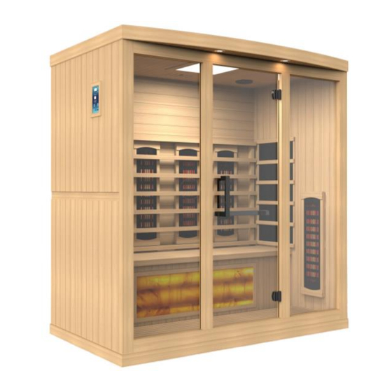
GDI-8010-02 / GDI-8020-02 / GDI-8030-02 / GDI-8040-02
1-2, 2, 3, & 4 Person Saunas
OWNER'S MANUAL
FOR CARBON MODEL SAUNAS
INDOOR USE ONLY
120VAC 15AMP DEDICATED CIRCUIT REQUIRED (GDI-8010-02 / GDI-8020-02)
120VAC 20AMP DEDICATED CIRCUIT REQUIRED (GDI-8030-02 / GDI-8040-02)
Carefully and thoroughly read this Owner's Manual before using/operating the
sauna. We recommend keeping this Owner's Manual for regular review and future
reference. Parts and accessories may vary and are subject to change.
1
Advertisement

Subscribe to Our Youtube Channel
Related Manuals for GoldenDesigns GDI-8010-02


Summary of Contents for GoldenDesigns GDI-8010-02
- Page 1 OWNER’S MANUAL FOR CARBON MODEL SAUNAS INDOOR USE ONLY 120VAC 15AMP DEDICATED CIRCUIT REQUIRED (GDI-8010-02 / GDI-8020-02) 120VAC 20AMP DEDICATED CIRCUIT REQUIRED (GDI-8030-02 / GDI-8040-02) Carefully and thoroughly read this Owner’s Manual before using/operating the sauna. We recommend keeping this Owner’s Manual for regular review and future...
- Page 2 TABLE OF CONTENTS Packing List Visual Assembly Diagrams Parts Description Assembly Instructions Operating the Sauna Tips for Using Your Sauna Safety Instructions Safeguards for Your Sauna Troubleshooting Guide Warranty Warranty Card WARNING: Visually inspect all heaters before assembly to make sure they are not damaged.
- Page 3 What Are Infrared Rays? Infrared is the band of light we perceive as heat. We cannot see this band of light with the naked eye, but we can feel this type of light in the form of heat. Our sun produces most of its energy output in the infrared segment of the spectrum.
- Page 4 EMF Levels from Common Homes Sources After many years and numerous studies on EMF exposure, no government body including the Occupational Safety and Health Administration (OSHA) have established permissible exposure limits (PEL). Currently, there is no consensus on the potential health hazard from any exposure to EMF.
- Page 5 HOW IT WORKS Infrared Saunas differ from traditional saunas in that they use infrared radiant energy to directly penetrate into the body's tissue to produce perspiration. Traditional saunas use steam to heat the air inside the sauna, which then heats your body until you begin to perspire.
- Page 6 *PLEASE READ INSTRUCTIONS BEFORE ASSEMBLY* GDI-8010-02 *The above assembly diagram i s for a quick reference visual guide only. All sauna models are not shown. Parts and accessories may vary and are subject to change. Near Infrared Heaters and backrests are sold separately.
- Page 7 *PLEASE READ INSTRUCTIONS BEFORE ASSEMBLY* GDI-8020-02 *The above assembly diagram i s for a quick reference visual guide only. All sauna models are not shown. Parts and accessories may vary and are subject to change. Near Infrared Heaters and backrests are sold separately.
- Page 8 *PLEASE READ INSTRUCTIONS BEFORE ASSEMBLY* GDI-8030-02 *The above assembly diagram i s for a quick reference visual guide only. All sauna models are not shown. Parts and accessories may vary and are subject to change. Near Infrared Heaters and backrests are sold separately.
- Page 9 *PLEASE READ INSTRUCTIONS BEFORE ASSEMBLY* GDI-8040-02 *The above assembly diagram i s for a quick reference visual guide only. All sauna models are not shown. Parts and accessories may vary and are subject to change. Near Infrared Heaters and backrests are sold separately.
- Page 10 PARTS DESCRIPTION GDI-8010-02 NOTE: The pictures and diagrams shown within this owner’s manual are representations of this model. Actual model may vary. Design and Construction are subject to change. Backrests are sold separately.
- Page 11 PARTS DESCRIPTION GDI-8020-02 NOTE: The pictures and diagrams shown within this owner’s manual are representations of this model. Actual model may vary. Design and Construction are subject to change. Backrests are sold separately.
- Page 12 PARTS DESCRIPTION GDI-8030-02 NOTE: The pictures and diagrams shown within this owner’s manual are representations of this model. Actual model may vary. Design and Construction are subject to change. Backrests are sold separately.
- Page 13 PARTS DESCRIPTION GDI-8040-02 NOTE: The pictures and diagrams shown within this owner’s manual are representations of this model. Actual model may vary. Design and Construction are subject to change. Backrests are sold separately.
- Page 14 Power Supply (Control Box) The POWER SUPPLY is the control center of the sauna room. It is installed on the topside of the ROOF PANEL and has inputs/outputs connected to it. (see Figure 1) Figure 1 POWER IN - main power of the sauna room HT1, HT2, HT3, HT4, HT5, HT6 –...
- Page 15 HT1, HT2, HT3, HT4, HT5, HT6 – Heater cords connect the heat emitters to the POWER SUPPLY at these ports (HT5 & HT6 are not used on most models) Lighting – Connects the interior lighting to the POWER SUPPLY at this port LampRoof –...
- Page 16 Floor Heater Cord Notch Cutouts Figure 4 Front of Sauna Room V. Panel Descriptions For easier installation, please understand and distinguish the differences between each panel. A. Floor Panel When you place the FLOOR PANEL at its designated location, leave enough space so that you are able to move around the FLOOR PANEL in order to install the sauna wall panels.
- Page 17 Figure 6 Figure 6a C. Roof Panel The ROOF PANEL houses the power supply, speakers, MP3 AUX jack, and reading lamp. Once installed, all the wiring harnesses, plugs, and connections will sit on the exterior side of the roof panel. Assembly Instructions A.
- Page 18 B. Installing the FLOOR PANEL 1. Place the FLOOR PANEL on the floor. Make sure the front side of the FLOOR PANEL is facing the correct direction. Please note the heater cord coming out of the topside of the floor panel at the rear right. (see Panel Descriptions) (see Figure 7) Figure 7 Front of Sauna Room...
- Page 19 D. Installing the REAR WALL PANEL 1. Remove the protection paper/tape (if present) from the buckles on the REAR WALL PANEL. Place the REAR WALL PANEL up onto the FLOOR PANEL. Next, attach the REAR WALL PANEL to the LEFT SIDE WALL PANEL and use the buckles to latch together.
- Page 20 Figure 11 E. Installing the HIMALAYAN SALT BLOCK PANEL and BENCH 1. Installing the HIMALAYAN SALT BLOCK PANEL can be done by sliding it downward between the two side wall panels. (see Figure 12) 2. Plug in the FLOOR HEATER cord and light connection (for the HIMALAYAN SALT BLOCK illumination) into the corresponding wall outlets.
- Page 21 F. Installing the ROOF PANEL 1. The side of the ROOF PANEL with the power supply (control box) is the top of the roof panel. 2. The edge with the curve is the front of the ROOF PANEL. Be careful of the wires coming from the SIDE and REAR PANELS when you set the ROOF PANEL down onto the panels.
- Page 22 Before Connecting After Connecting Figure 14 Figure 15 Figure 16 H. Installing the TEMPERATURE SENSOR and optional accessories (varies by model) 1. Enter the sauna and remove the protective covering (masking tape) from the TEMPERATURE SENSOR. Situate the TEMPERATURE SENSOR so that it is vertical and pointing downward.
- Page 23 Figure 18 Figure 19 I. Installing RADIO HOUSING BOX and RADIO (radio model subject to change) 1. If your RADIO HOUSING BOX is already assembled, then proceed to step 4. Locate the wood sides for the RADIO HOUSING BOX. There is one for the front, side, and bottom. (see Figure 20, Figure 21, and Figure 22) 2.
- Page 24 Figure 21 Figure 22 Figure 23 Figure 24 Figure 25 Figure 26 Antenna Connection Figure 27...
- Page 25 J. Putting on the ROOF COVER (Optional) 1. Place the ROOF COVER over the top of the sauna. Be cautious when pulling the power cord through the hole in the roof cover. Gently place the ROOF COVER onto the ROOF PANEL. When the edges are aligned, screw the ROOF COVER to the roof panel.
- Page 26 Control Panel Power On/Off: Press to control the main power of the sauna Power Indicator: Indicates the status of the sauna’s main power Work Start/Stop: Press to control the working functions of the sauna Work Indicator: Indicates the working status of the sauna Heat Indicator: Indicates the status of heating function Light: Press to control the lighting function Time Display: Displays the heating time of the sauna in...
- Page 27 5. Heating times do vary. Generally, it will take approximately twenty to thirty minutes to preheat the sauna to the average used temperature range of approximately 118 degrees Fahrenheit / 48 degrees Celsius. When the ambient temperature is low, heating requires additional time. For the first few times of use, you may use 115 degrees Fahrenheit / 46 degrees Celsius as a reference starting point for a time period of about 20 to 30 minutes (this represents the actual time you are in the sauna at the desired temperature).
- Page 28 (depending on sauna model) *35-40 minutes to reach about 125-130 degrees Fahrenheit/52-54 degrees Celsius (depending on sauna model) *45-60 minutes to reach up to approximately 135 degrees Fahrenheit/57 degrees Celsius (depending on sauna model) Please keep in mind that you can either preheat the sauna to the set temperature before entering or sit inside the sauna as the temperature rises.
- Page 29 8. To treat your ankles and feet more effectively, you can elevate them and move them close to one of the heat emitters to achieve a deep heating effect. 9. To utilize the sauna’s heat therapy effect, put oil and treatment into your hair and wrap it with a towel.
- Page 30 the sauna. Some medications may induce drowsiness while other may affect the heart rate, blood pressure, and/or blood circulation. 10. Use care when exercising before and after sauna use. 11. Never sleep inside the sauna 12. Do not use any type of cleaning agents on the interior of the sauna. Only wipe down the sauna room with water and a damp cloth.
- Page 31 Safeguards For Your Sauna 1. Do not install the sauna near water, near a bathtub (if water will splash on the sauna), near a shower (if water will splash on the sauna), in a wet basement, or near a swimming pool (if water will splash on the sauna). 2.
- Page 32 Check that the heat emitter cords are properly connected snug and tight. If the issue continues, then the particular heat emitter may be damaged. Do not continue to operate. Contact the manufacturer for replacement parts. Solution: If the heat emitters are not working and there is a “-L” for the temperature reading, then the temperature sensor may not be plugged in properly or it may be damaged or the power supply may be defective.
- Page 33 Before contacting Customer Service, remove the wood frame holding the control panel in place to gain access to the “CTRL” connection behind the control panel. Once you remove the control panel from the wall panel, you can disconnect and reconnect the connection making sure it is snug and tight.
- Page 34 interior ceiling above your head as you sit on the bench. Disconnect the connection and reconnect to make sure the connection is snug and tight. 4. The individual watching the control panel can let you know if the "-L" ever changed. If the "-L" is still displayed on the control panel, then we need to rule out a control panel issue.
- Page 35 outlet. You will need to contact Customer Service if the power supply cord is damaged as the power supply will need to be replaced. 6. Bluetooth Solution: Please note that you can only have a single device connected to the Bluetooth at any given time. You must unpair your device before connecting with another device.
- Page 36 other receptacles when the sauna is in operation. Both of these options are acceptable. 10. Lower Heat Emitters Solution: With regards to the lower heat emitters under the bench and on the floor, these heat emitters operate a bit different than the wall heat emitters.
- Page 37 person inside the sauna room and pushing on the rear wall panel outward, a second person should be able to latch the buckles. Make sure that the wall is fitting together like a puzzle as one wall panel fits into the other. Work your way down from top to bottom.
- Page 38 Limited Lifetime Warranty 7 Year Limited Warranty: Golden Designs, Inc. under the Dynamic brand name and other brand names warranties the wood, structure, heating elements, and electronics against defects in material and workmanship for a period of 1 to 5 years from the original date of purchase.
- Page 39 ▪ Normal wear and tear or weathering ▪ Use of product not in accordance with instructions ▪ Worn out receptacle Surface cracks are not considered defects in material or workmanship, as they are normal characteristics of all woods. This includes minor cracks due to wood expansion and contraction.
- Page 40 THIS PAGE IS INTENTIONALLY LEFT BLANK...
- Page 41 WARRANTY CARD Congratulations on your purchase of an Infrared Sauna from Golden Designs, Inc. Please take the time to complete the following Warranty Card and mail it back to: Golden Designs, Inc. 3550 Jurupa Street, Unit B Ontario, CA 91761 Please include a copy of your sales receipt showing date of purchase as this will serve as proof of purchase.
Need help?
Do you have a question about the GDI-8010-02 and is the answer not in the manual?
Questions and answers