FAAC 770 Manual
In-ground swing gate operator
Hide thumbs
Also See for 770:
- Manual (44 pages) ,
- Quick start manual (16 pages) ,
- Installation manual (11 pages)
Table of Contents
Advertisement
Advertisement
Table of Contents

Related Manuals for FAAC 770


Summary of Contents for FAAC 770
- Page 1 In-ground Swing Gate Operator UL325 - UL991 FAAC International Inc. FAAC International Inc. Headquarter & East Coast Operations West Coast Operations 3160 Murrell Road 357 South Acacia Avenue Rockledge, FL 32955 Fullerton, CA 92831 Tel. 800 221 8278 www.faacusa.com...
-
Page 2: Table Of Contents
INSTALLATION 2.1. Preliminary Checks 2.2. Installing the foundation box 2.3. Setting up the gate 2.4. Installing the Operator POSITIVE STOPS MANUAL OPERATION 4.1. Restoring Normal Operation MAINTENANCE AND REPAIRS SPARE PARTS DIAGRAM E024U CONTROL BOARD 770 Rev. B September 2016... -
Page 3: Important Safety Information
Locate one or more non-contact sensors where the risk of entrapment or obstruction exists, such as at the reachable perimeter of a moving gate or barrier. • Use only “FAAC Photobeam” or “EMX IRB-RET” photo- electric eyes to comply with UL325. -
Page 4: General Safety Precautions
Install devices such as reversing edges and photo conditions. beams to provide better protection for personal • Use only FAAC MSE MO, CN60 or M60 edge sensors. property and pedestrians. Install reversing devices that are appropriate to the gate design and application. -
Page 5: Ul325 Gate Operator Classifications
Installing the Warning Signs This FAAC swing gate operator is supplied with two warning signs to alert people that a possible hazard exists and that appropriate actions should be taken to avoid the hazard or to reduce exposure to it. -
Page 6: Description & Specifications
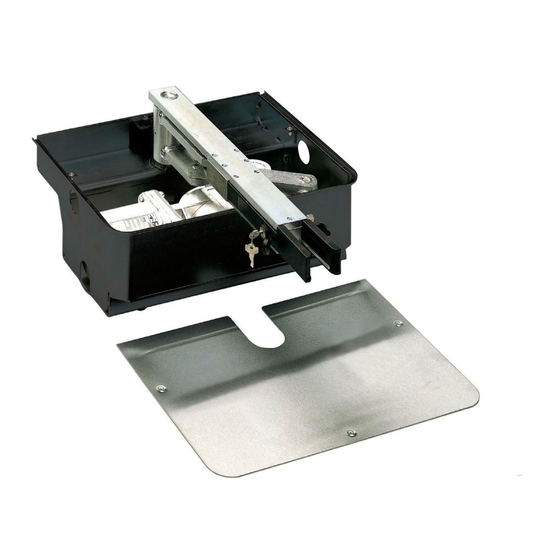
770 OPERATOR 1.2 Electrical Setup 1. DESCRIPTION AND SPECIFICATION The FAAC 770 is an electromechanical operator for swing gates. It is designed for in-ground installation and therefore does not alter the appearance of the gate. The supplied support box allows you to setup the gate before actually installing the operator. -
Page 7: Installing The Foundation Box
Installing the foundation box Dig a hole for the foundation box as shown in Fig. 5. 2. Place the foundation box in the hole, refer to the dimen- sions provided in Figs. 6a and 6b. The center of the pivot on the foundation box must be per- fectly aligned with the leaf’s axis of rotation (Figs 6a and 6b). -
Page 8: Installing The Operator
• Determine the correct location of the leaf on the “U” profile with reference to the axis of rotation (Fig. 10a and 10b); • Close the “U” profile on the post side with a small plate, as shown in Figs. 10a and 10b. Fig. -
Page 9: Positive Stops
4. Turn the key in the direction of the post, as far as it will go manual operation. (Fig. 16 - Ref. 3). REPAIRS 5. Pull the lever out (Fig. 16 - Ref. 4). For repairs, refer to an authorized FAAC service center. 6. Operate the leaf manually. -
Page 10: Spare Parts Diagram
5. SPARE PARTS DIAGRAMS Part Part Number Description 770770 770 24V Motor 716078 Gear Box 727158 Gear Box Cover 718075 Secondary Shaft 718076 Internal Shaft Group 719165 Slow Shaft 390451 Seal Kit 63000452 63000590 V-Ring Seal And Spacer... - Page 11 Part Part Number Description 63000422 Release Levers Kit With Locks 63003015 Steel Ball 7271985 Cover Plug 727157 Box Cover 390477 Articulated Lever 424010 Manual Release Assembly...
-
Page 12: E024U Control Board
1. E024U CONTROL BOARD DESCRIPTION & CHARACTERISTICS This manual refers to board version SETTING DL14 DL15 DL16 DL17 DL18 DL19 DL20 DL21 DL22 Fig. A1 1.1 TECHNICAL SPECIFICATIONS 1.2 LAYOUT AND COMPONENTS RADIO Main power supply Connector for the radio receiver 115 V~ 60 Hz BATTERY Secondary power... - Page 13 2. INPUT / OUTPUT DESCRIPTION Encoder 24 VDC Maglock B STP CL OP OPEN Fig. A2 LABEL FUNCTION 2 EASY 2 EASY 2easy BUS input for encoders (S800H and S450H only), XIB and loop detector boards OPEN A N.O. Contact for total opening command OPEN B: N.O.
- Page 14 3. SAFETY DEVICE CONNECTIONS Entrapment protection To comply with the UL325 standard for gate operators every Connection of One Pair of Monitored Closing Photocells entrapment zone, as defined in ASTMF2200, must be pro- tected by two independent entrapment protection devices. One of the devices is inherent in the E024U control boards design, the other can be external, like a photocell or an edge sensor.
- Page 15 Only one monitored photocell can be connected to the Connection of One Pair of Closing Photocells Closing or Opening safety inputs. More than one photocell (monitored), One Pair of Opening Photocells or other device can be connected to the safety inputs, but (monitored) and One pair of Opening/Closing they will not be monitored.
-
Page 16: Operating Logic
4. PROGRAMMING 4.1 DIP SWITCH DS1 SETTINGS FOR OPERATING LOGIC OPERATING LOGIC DS 1: SW 1 - SW 2 - SW 3 PAUSE LOGIC SW 1 SW 2 SW 3 DESCRIPTION TIME E (default) One command opens, the next one closes. A command during opening stops the gate Semiautomatic 0 - 4... - Page 17 4.2 ADJUSTING TRIMMERS – FORCE ADJUSTMENT MOTOR 1 Turn clockwise to increase the opening and closing force TR 2 – FORCE ADJUSTEMENT MOTOR 2 Turn clockwise to increase the opening and closing force TR 3 – SPEED ADJUSTMENT FOR MOTOR1 AND MOTOR 2 Turn clockwise to increase the opening and closing speed TR 4 –...
- Page 18 4.3 DIP SWITCH DS1 SETTINGS FOR BOARD SETUP BOARD SETUP DS 1: SW 4 to SW 12 The opening of leaf 2 is delayed after the opening of leaf 1. This is to avoid SW 4 OPENING DELAY the gate leafs interfering with each other during the initial part of the move- 0 sec (default) ment.
- Page 19 SW 4 S450H, S800H Active only for 3 sec. after an open impulse (from gate closed) S418 Active always except 3 sec. before an opening 415, 390, 770 5. LED DIAGNOSTICS SETTING Reserved DL14 DL15 DL16 DL17 DL18 DL19 DL20 DL21...
- Page 20 LED STATUS In BOLD the normal state with gate closed and working DESCRIPTION ON STEADY BLINKING Board working on AC Board working on LED BATTERY Battery charging power battery power or ext supply LED +24 Main power present Main power OFF SLOW BLINK (1 sec.
- Page 21 The diagnostic LED shows only one error condition at a time, with the priority of the below table. In case there is more than one error once one is eliminated the LED will show the next LED ERROR DISPLAY NUMBER OF ERROR CONDITION SOLUTION FLASHES...
- Page 22 At the point where you want the slowdown to start give an This is a more detailed description of what happens after an OPEN A command with the push button or the remote that obstacle detection: is already stored in memory. Leaf 2 starts to slow down and Gate opening, obstacle detected: stops when it reaches the mechanical stop or FCA2.
- Page 23 On the back panel there are: the control board, the power supply AC POWER CONNECTION and additional accessories. To connect AC power to the controller: 1. Turn the circuit breaker for the AC gate operator power OFF before connecting the AC input wires. Power outlet AC connection and switch...
- Page 24 For the upgrade you need a USB Flash Drive, where you have BLACK 12VDC, 8 amp Battery to copy the file supplied by FAAC. Then follow these steps: JUMPER Disconnect the batteries if they are present. 12VDC, 8 amp Turn the AC power off and insert the Flash Drive into the...
- Page 25 11. FUNCTION LOGICS LOGIC “E” PULSES SYSTEM STATUS OPEN A OPEN B STOP FSW OP FSW CL FSW CL/OP no effect no effect no effect CLOSED opens the leaves opens leaf 1 no effect (OPEN disabled) (OPEN disabled) (OPEN disabled) stops and opens at release immediately stops operation...
- Page 26 LOGIC “EP” PULSES SYSTEM STATUS OPEN A OPEN B STOP FSW OP FSW CL FSW CL/OP no effect no effect no effect CLOSED opens the leaves opens leaf 1 no effect (OPEN disabled) (OPEN disabled) (OPEN disabled) stops and opens at release immediately OPENING stops operation (1) stops operation...
- Page 27 LOGIC “B” PULSES SYSTEM STATUS OPEN A OPEN B STOP FSW OP FSW CL FSW CL/OP no effect no effect no effect CLOSED opens the leaves no effect no effect (OPEN disabled) (OPEN disabled) (OPEN disabled) stops and, at release, closes OPENING no effect closes leaves...
- Page 28 12. ACCESSORIES 12.1 SHADOW LOOP INTERFACE (p/n 790062) XIB board connections with no opening safety Through the use of the XIB interface board you can connect an additional loop detector (center or shadow) to the E024U board to keep the gate open if vehicles are obstructing the Interface closing path.
- Page 29 XIB board connections and second opening safety XIB board connections and only one opening safety Interface Interface N.C. N.C. Encoder N.O. Encoder N.O. Detector Detector Open Safety Open Safety 2 Open Safety 1 Receiver Fig. A12a Fig. A13a Receiver Receiver TRANSMITTER PHOTOCELL 1 TRANSMITTER...
- Page 30 The face board will blink briefly and then will stay ON solid if the board is designed to fit in the FAAC standard 16” x 14” enclo- BUS connection is working correctly. sure on the existing DIN rail. To connect the interface board:...
- Page 31 FAAC S.p.A. or FAAC International, Inc. The warranty herein FAAC International, Inc.’s obligations under above set forth shall not be deemed to cover...
- Page 32 © 2016, FAAC International, Inc. - All Rights Reserved Published in Sept. 2016...
Need help?
Do you have a question about the 770 and is the answer not in the manual?
Questions and answers