Table of Contents
Advertisement
Quick Links
I N S T R U C T I ON MA N U A L
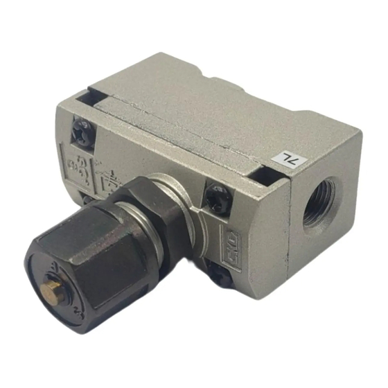
S P E E D C O N T R O L L E R
S C 1 −6 N ・ 8 N ・ 1 0 N ・ 1 5 N
Please read this instruction manual
●
carefully before using this product, par-
ticularly the section describing safety.
Retain this instruction manual with the
●
product for further consultation whenever
necessary.
S M−3 0 8 4 7 1 −A
Advertisement
Table of Contents

Related Manuals for CKD SC1-6N


Summary of Contents for CKD SC1-6N
- Page 1 S M−3 0 8 4 7 1 −A I N S T R U C T I ON MA N U A L S P E E D C O N T R O L L E R S...
- Page 2 F o r S a f e t y U s e To use this product safety, basic knowledge of pneumatic equipment, including materials, piping, electrical system and mechanism, is required (to the level pursuant to JIS B 8370 Pneumatic System Rules).
- Page 3 INDEX SC1-6N・ 8N・ 10N・ 15N Speed Controller Manual No. SM-308471-A 1. PRODUCT Specification ・・・・・・・・・・・・・・・・・・・・・・・・・・・・・・・・・・・・・・・・ External Dimension , Internal structure and J I S Symbol ・・・・・・・・・・・・・・・・ Fundamental Circuit Diagram ・・・・・・・・・・・・・・・・・・・・・ 2. CAUTION Fluid ・・・・・・・・・・・・・・・・・・・・・・・・・・・・・・・・・・・・・・・・・・・・・・・ 3. OPERATION ・・・・・・・・・・・・・・・・・・・・・・・・・・・・・・・・・・・・・・・・・・・ 4. INSTALLATION Piping ・・・・・・・・・・・・・・・・・・・・・・・・・・・・・・・・・・・・・・・・・・・・・・...
-
Page 4: Specifications
Connecting port diam 6N : Rc1/8 8N : Rc1/4 10N : Rc3/8 15N : Rc1/2 Mounting screws 2-M4 Depth 6 (SC1-6N・8N) 2-M5 Depth6 (SC1-10N・15N) Markings Model code SC1-6N, 8N SC1-10N, 15N ―3― [SM‑308471‑A] ... - Page 5 1 PRODUCT 2) Internal structure and major parts list Part name Material Remark ① Needle C3604BD E type snap ring ② Knob ZDC2 However, for the ③ high-temperature Needle guide ADC12 ④ type, the mate- Lock nut ZDC2 rial (NBR) ⑤...
- Page 6 2 CAUTION 2. CAUTION 2.1 Fluid 1) Use the compressed air, filtrated and dehumidified. Carefully select a filter Compressed air Filtrated air of an adequate filtration rate (5μm or lower preferred), flow rate and its mounting location (asclosest to direc- tional control valve as possible) 2) Be sure to drain out the accumulation Upper limit of...
-
Page 7: Operation
3 OPERATION 3. OPERATION Open Close JIS symbol marking Setting the cylinder speed Turning the handle ① clockwise re- duces the speed of cylinder, finally closing the controller, while turning it counterclockwise increases the speed of cylinder. To build a meter out cir- cuit, close the controller first by turn- ing its handle ①... -
Page 8: Installation
4 INSTALLATION 4. INSTALLATION 4.1 Piping 1) For piping beyond the filter, use pipes that are tough against corrosion such as galvanized pipes, nylon tubes, rubber tubes, etc. (Refer to Selection Guide Table for Related Equipment.) 2) See to it that the pipe connecting cylinder and solenoid valve has effective sectional area which is needed for the cylinder to drive at the specified speed. - Page 9 4 INSTALLATION 7) For the prevention of the leakage and breakage, tighten the screw within the limits of the adequate tightening torque mentioned below. Tightening torque Connection screw Tightening torque N・m NPT 1/8 3 to 5 NPT 1/4 6 to 8 NPT 3/8 13 to 15 NPT 1/2...
-
Page 10: Maintenance
5 6 MA I NT E NANCE HOW TO ORDER 5. MAINTENANCE 5.1 Trouble shootig Trouble Causes Remedies 1. The controller is installed in Reaffirm the direction of flow and the erroneous direction per correct it if found the connection is Turning the handle of control- specified on the schematics.
Need help?
Do you have a question about the SC1-6N and is the answer not in the manual?
Questions and answers