
Related Manuals for Inficon Sensistor Sentrac SEN.122.164


Summary of Contents for Inficon Sensistor Sentrac SEN.122.164
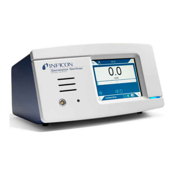
- Page 1 Operating Instructions ® ® Sensistor Sentrac Hydrogen Leak Detector Catalog No. Type number: SEN.122.164, SEN.122.165, SEN.122.166 From software version 3.01.01 nind65en1-01-(2304)
- Page 2 INFICON AB Wahlbecksgatan 25A SE-582 13 Linköping Sweden...
-
Page 3: Table Of Contents
INFICON Table of Contents Table of Contents 1 General Information ............................ 7 1.1 About this Document.......................... 7 1.1.1 Document History ......................... 7 1.2 Introduction to the Instrument ........................ 7 1.2.1 Intended Use.......................... 7 1.2.2 Available Models........................... 8 1.3 Warnings .............................. 9 2 Equipment and Storage .......................... - Page 4 Table of Contents INFICON 8 Menu System .............................. 25 8.1 Instrument Display .......................... 25 8.1.1 Menu Navigation ......................... 25 8.1.2 Menu Buttons.......................... 27 8.1.3 Navigation and Other Buttons..................... 27 8.2 Passwords and Menu Overview...................... 27 9 Operating the Instrument .......................... 30 9.1 Preparation.............................
- Page 5 17.1 Interfaces and Connectors ........................ 55 17.1.1 USB-C Port .......................... 55 17.1.2 Probe Control Port ........................ 55 17.1.3 INFICON I/O Module........................ 56 17.1.4 Probe Connection Port........................ 56 17.1.5 Power Input (Desktop Model) ..................... 56 17.1.6 Power Input (Portable Model) ..................... 56 17.1.7 Power input (Panel model)......................
- Page 6 INFICON 19 Support from INFICON.......................... 61 19.1 How to Contact INFICON........................ 61 19.2 Returning Components to INFICON ...................... 61 20 Declarations of Conformity ......................... 62 21 Removal of the Battery (Portable Model) .................... 64 22 Disposing of the Instrument........................ 66 23 Appendix ...............................
-
Page 7: General Information
INFICON General Information | 1 1 General Information Read this Manual carefully before putting your instrument into service. When reading, pay particular attention to the WARNINGS, CAUTIONS and NOTICES found throughout the text. DANGER To prevent injury or death, use the product only as instructed and use only the accessories that have been supplied or recommended. -
Page 8: Available Models
1 | General Information INFICON 1.2.2 Available Models Fig. 1: Available Models Sensistor Sentrac Part no. Sensistor Sentrac, desktop model For stationary use 590-970 Sensistor Sentrac, portable model 12 hours operating time on 590-971 batteries Sensistor Sentrac, panel model For panel mounting... -
Page 9: Warnings
INFICON General Information | 1 1.3 Warnings DANGER Imminent threat resulting in death or serious injuries WARNING Hazardous situation resulting in potential death or serious injuries CAUTION Hazardous situation resulting in minor injuries NOTICE Hazardous situation resulting in damage to property or the environment... -
Page 10: Equipment And Storage
2 | Equipment and Storage INFICON 2 Equipment and Storage When receiving the equipment, check that it has not been damaged during transport. 2.1 Desktop Model Setup Pos. Part Part no. Instrument Unit Desktop Model 590-970 Hand Probe P60 or Strix... -
Page 11: Portable Model Setup
INFICON Equipment and Storage | 2 2.2 Portable Model Setup Pos. Part Part no. Instrument Unit Portable Model 590-971 Hand Probe P60 or Strix 590-890, 590-730 Probe Cable (3, 6 or 9 m) 590-161, 590-175, 590-165 Battery Charger 591-795 Sample Kit Probe Tip... -
Page 12: Panel Model Setup
2 | Equipment and Storage INFICON 2.3 Panel Model Setup Pos. Part Part no. Instrument Unit Panel Model 590-972 Hand Probe P60 or Strix 590-890, 590-730 Probe Cable (3, 6 or 9 m) 590-161, 590-175, 590-165 External DC Power Cable Assembly... -
Page 13: Peripheral Equipment
INFICON Equipment and Storage | 2 2.4 Peripheral Equipment Pos. Part Tracer gas Compressed Air Tracer Gas Filler Two-Step Gas Regulator Calibration Leak with Certificate Calibration Gas with Certificate Compressed Air Filter For more information, see “Spare Parts [} 58]”. Sensistor_Sentrac_Combined_Operating_Manual_nind65en1-01-(2304) -
Page 14: Storage Environment Sensistor Sentrac
2 | Equipment and Storage INFICON 2.5 Storage Environment Sensistor Sentrac Desktop Model (590-970) Temperature: 0°C - 45°C (32°F - 113°F) Humidity Range: 10% to 75% RH (non-condensing) Portable Model (590-971) Temperature: 0°C - 45°C (32°F - 113°F) Humidity Range:... -
Page 15: Instrument Description
INFICON Instrument Description | 3 3 Instrument Description The instrument is manually controlled by the touchscreen menu system. The screen also shows results and sequence graphically and in plain text. 3.1 Front View Pos. Port/Interface Port Earphone Jack Probe Connector... -
Page 16: Rear View
External 24 V DC power supply Panel Model) Probe Control Port PLC I/O, e.g. AP29ECO. Note: The Probe Control Port is not active on the Portable model INFICON I/O Module Port INFICON I/O Module Probe Connector Port Probe Power Input (Desktop Model) Power Cable... -
Page 17: Labels
INFICON Instrument Description | 3 3.3 Labels At the rear side of the instrument, a label indicates the electrical specifications of the instrument and its serial number. Pos. Labels Label Desktop Model Label Portable Model Label Panel Model Connections Label SEN. -
Page 18: Hand Probe
4 | Hand Probe INFICON 4 Hand Probe NOTICE Connection and disconnection of the sensor cable must be done with power off. Sensor can be damaged if power is on. The Hand Probe is a no-flow probe. Gas sensing takes place in the replaceable sensor located in the tip of the probe. -
Page 19: Description Of Strix Hand Probe
INFICON Hand Probe | 4 NOTICE Do not expose the probe to a hydrogen concentration as large as 5% when the instrument is not powered on, as this could damage or destroy the probe gas sensor. For more information see “Spare Parts [} 58]”. -
Page 20: System Examples
5 | System Examples INFICON 5 System Examples 5.1 Desktop Model Pos. Description Sensistor Sentrac Desktop Model Compressed Air Tracer Gas Tracer Gas Filler e. g. TGF11 Hand Probe Test Object Evacuation and Gas Filling 20 / 72 Sensistor_Sentrac_Combined_Operating_Manual_nind65en1-01-(2304) -
Page 21: Portable Model
INFICON System Examples | 5 5.2 Portable Model Pos. Description Sensistor Sentrac Portable Model Hand Probe Test Object Sensistor_Sentrac_Combined_Operating_Manual_nind65en1-01-(2304) 21 / 72... -
Page 22: Panel Model
5 | System Examples INFICON 5.3 Panel Model Pos. Description Sensistor Sentrac Panel Model COMBOX 60 AP29ECO Accumulation Chamber 22 / 72 Sensistor_Sentrac_Combined_Operating_Manual_nind65en1-01-(2304) -
Page 23: Setup
Connect the Hand Probe to the instrument using the probe cable. If you have purchased another type of probe than the hand probes Strix or P60, contact INFICON for help. Adaptation equipment between probe and instrument may be required. Plug the power cable into the power inlet of the instrument and into the nearest power socket. -
Page 24: Settings
• The log file is stored on the Internal Memory. See “Export [} 42]”: “Info > Export/Import > Export” how to export log files. • The INFICON I/O module port can be activated in the check box in the Bus Module tab. -
Page 25: Menu System
8.1 Instrument Display 8.1.1 Menu Navigation NOTICE Do not cause any damage by sharp objects on the instrument touchscreen. INFICON recommends using the fingertip for touching the touchscreen. Icon colors Grey Shows top screen in current menu. clickable Light blue Clickable Click to enter menu. - Page 26 8 | Menu System INFICON Settings Screen RECIPE CALIBRATION GENERAL LOCATING MODE COMMUNICATION MEASURING MODE PROBE PASSWORD Settings Info Screen STATISTICS ABOUT EXPORT / IMPORT Info Diagnosis Screen WARNINGS RESET FILES SERVICE SCREEN Diagnosis 26 / 72 Sensistor_Sentrac_Combined_Operating_Manual_nind65en1-01-(2304)
-
Page 27: Menu Buttons
INFICON Menu System | 8 8.1.2 Menu Buttons Icon Description Icon Description Settings Combined Mode Operation Audio Info Mute Diagnosis Sensitivity Measuring Mode Calibration Locating Mode Recipe 8.1.3 Navigation and Other Buttons Icon Description Icon Description Start Load Stop, Close... - Page 28 8 | Menu System INFICON If the password is not set, the user can operate, calibrate, change settings, edit or review logs as an Advanced user. Passwords and Menu Overview All menus except the service menu is available when the use of passwords is not activated.
- Page 29 INFICON Menu System | 8 Menu Menu Tabs Access level Basic Inter- Advanced Level 1 Level 2 mediate Info Statistics Run Time Export/Import Export Import About Diagnosis Warnings Warnings Service screen Signals Graph Tools Test Board Reset Factory Default Calibration...
-
Page 30: Operating The Instrument
9 | Operating the Instrument INFICON 9 Operating the Instrument 9.1 Preparation NOTICE Do not expose the probe to a hydrogen concentration as large as 5% when the instrument is not powered, as this could damage or destroy the probe sensor. -
Page 31: Settings
INFICON Operating the Instrument | 9 The battery charger will not restart automatically when the battery runs low if you leave battery charger connected. For stationary operation you must do the following: When battery is low, connect the battery charger. -
Page 32: How To Detect Leaks
9 | Operating the Instrument INFICON Click the Sensitivity icon on the Operation Screen and set the Sensitivity. The Sensitivity setting can be set to change automatically to lower sensitivity, when exposed to larger leaks, by clicking the Auto Locating Range Enable check box in the Settings / Locating mode menu. -
Page 33: Measuring Leaks
INFICON Operating the Instrument | 9 cc/s Air Measuring Mode Calibrate the probe. See “Calibration [} 38]”. Click the measuring Mode icon on the Operation Screen. Default unit in Measuring Mode is cc/s. To set it to other units click “Settings >... -
Page 34: Hands On
9 | Operating the Instrument INFICON 9.4 Hands On It is important to have a correct calibration when measuring the size of a leak in Measuring Mode and Combined Mode. Calibrate the probe before measuring, see “Calibration [} 38]”. Ensure that the test object is pressurized properly before performing a test. - Page 35 INFICON Operating the Instrument | 9 Combined Mode screen by clicking the Show Reject Level check box in the Settings / General menu. Operation without a Reject Level is achieved by setting it to 0, which is the default setting.
-
Page 36: Recipes
10 | Recipes INFICON 10 Recipes A recipe is a collection of settings suited for a particular test setup. This is used for having different settings for different test objects. Calibration settings are not saved in the recipe. A calibration leak or calibration gas is normally used to calibrate the instrument. -
Page 37: Select An Existing Recipe
INFICON Recipes | 10 10.2.3 Select an Existing Recipe Click “Settings > Recipe” to enter the Recipe menu. Check the Recipes active check-box to activate the use of recipes. Select a recipe in the list. Click the Load icon to load the recipe. -
Page 38: Calibration
• Calibration gas: Available at gas suppliers and has a known concentration of hydrogen (10 ppm hydrogen in synthetic air is recommended). • Calibration leak: Available at INFICON and has a fixed leak rate (mbar l/s or g/y). Both methods take less than 2 minutes to perform. -
Page 39: How To Calibrate
For more information see “Spare Parts and Accessories [} 58]”. 11.2 How to Calibrate INFICON support two types of Calibration Leak. The one with large leaks must be connected to tracer gas pressure to work. The small leak is connected to a small fillable gas container. -
Page 40: Calibration Procedure
11 | Calibration INFICON Example, Calibration Leak: Calibration Leak Rate is 4.2E-05 mbar l/s (95% N - 5% H Calibration Unit = mbar l/s Calibration Value = 4.2E-05 Calibration Leak Gas = 95% N - 5% H Example, Calibration Gas: Calibration Gas containing 10 ppm Hydrogen in synthetic air. - Page 41 INFICON Calibration | 11 Click the Start button or the Probe button. Expose the Probe to the Calibration Leak or the Calibration Gas. Keep it in exposed position while the Calibration in progress bar is moving. Remove the Probe when the display shows Remove probe and gives a sound signal.
-
Page 42: Info
12 | Info INFICON 12 Info 12.1 Statistics 12.1.1 Run Time ► To see the current operation time, click “Info > Statistics > Run Time”. 12.2 Export/Import 12.2.1 Export Backup of all useful settings, including recipes, can be exported to a USB memory stick. -
Page 43: About
INFICON Info | 12 Settings can only transferred between instruments with SW version 3.01.01 or later. 12.3 About ► To shown the serial number and software version of the instrument and probe, click “Info > About”. Sensistor_Sentrac_Combined_Operating_Manual_nind65en1-01-(2304) 43 / 72... -
Page 44: Diagnosis
13 | Diagnosis INFICON 13 Diagnosis 13.1 Warning ► To see a list of all occurred warnings, click “Diagnosis > Warnings”. This list can only be reset by authorized service personnel. 13.2 Service Screen This screen is used for servicing and repair. -
Page 45: Troubleshooting
INFICON Troubleshooting | 14 14 Troubleshooting 14.1 Fault Fault Symptom Fault Measures No sound in Detection Sound set low. Click the speaker icon to Mode and Analysis Mode. increase the volume Broken speaker or speaker Send in for repair. cable loose. -
Page 46: Warning Messages
14 | Troubleshooting INFICON Fault Symptom Fault Measures No picture on probe Probe PCB broken or Send in for repair. display probe display cable loose Low or no gas sensitivity. Old or broken gas sensor. Replace sensor. Probe broken. Send in probe for repair. -
Page 47: Maintenance Instructions
Electrical shock Do not open the instrument needlessly! Service of this equipment may only be carried out by service organizations authorized for this purpose by INFICON. Changing the battery is the only time when opening the instrument is needed and allowed. -
Page 48: Changing Probe Tip Filter (P60)
15 | Maintenance Instructions INFICON 15.2 Changing Probe Tip Filter (P60) Part Part no. Qty. Consumables Probe Tip Filter 591-234 Disassemble ► Remove the Probe Filter (A) using a needle. Assemble ► Install the new Probe Filter. 15.3 Changing Probe Tip Filter (Strix) Part Part no. -
Page 49: Changing Probe Protection Cap (P60)
INFICON Maintenance Instructions | 15 Assemble ► Install the new Probe Filter. 15.4 Changing Probe Protection Cap (P60) Part Part no. Qty Consumable Probe Tip Protection Cap 591-273 (set of 50) 590-625 (set of 500) Disassemble Attach the supplied Sensor Key at the bottom of the Probe Tip Protection Cap (A) and pull with one finger on each side of the probe tip. -
Page 50: Changing Probe Protection Cap (Strix)
15 | Maintenance Instructions INFICON 15.5 Changing Probe Protection Cap (Strix) Part Part no. Qty Consumable Probe Tip Protection Cap 590-300 (set of 50) 590-305 (set of 500) Disassemble 1. Attach the supplied Sensor Key at the bottom of the Probe Tip Protection Cap (A) and pull with one finger on each side of the probe tip. -
Page 51: Changing Probe Sensor (Strix)
INFICON Maintenance Instructions | 15 Disassemble Loosen the safety nut (A) using the Sensor Key. Remove the Sensor (B) by pulling it straight out. Assemble Carefully install the new Sensor. Make sure that the Probe Pipe (C) and Sensor connects correctly. -
Page 52: Software Update
15 | Maintenance Instructions INFICON Assemble Carefully install the new Sensor. Make sure that the Probe Pipe (C) and Sensor connects correctly. Use the markers on Probe Pipe and Sensor for correct alignment. Reinstall the safety nut (A). 15.8 Software Update Download the update folder containing two update files to a USB memory stick. -
Page 53: Service
CAUTION If the instrument suffers external damage, it must be checked and repaired by a service organization authorized by INFICON. In case of required service or repair, contact nearest INFICON service center. Please visit www.inficon.com for further information. Sensistor_Sentrac_Combined_Operating_Manual_nind65en1-01-(2304) 53 / 72... -
Page 54: Technical Data
17 | Technical Data INFICON 17 Technical Data Electrical Data Power supply (Desktop Model) 100-240 V (ac), 50/60 Hz, 67 W max. load Internal rechargeable battery (Portable Li-Ion, 14.5 V / 102 Wh (7000 mAh) Model) External 24 V DC power supply (Panel 24 VDC, 2.2 A... -
Page 55: Interfaces And Connectors
INFICON Technical Data | 17 Electrical Data Panel Model IP40 (front), IP20 (back) 17.1 Interfaces and Connectors CAUTION The outputs will be destroyed Outputs are not relay types. Do not connect external drive source such as 24 VDC or 100/230 VAC. -
Page 56: Inficon I/O Module
17 | Technical Data INFICON 17.1.3 INFICON I/O Module Connector: M12 8-pin 17.1.4 Probe Connection Port Cable: C21 Probe Cable 17.1.5 Power Input (Desktop Model) Cable: Power Cable 17.1.6 Power Input (Portable Model) Cable: Battery Charger 56 / 72 Sensistor_Sentrac_Combined_Operating_Manual_nind65en1-01-(2304) -
Page 57: Power Input (Panel Model)
WARNING The supplied External DC Power Cable (598-469) must be used. The 24 V DC power supply must be of SELV* type. INFICON can recommend TDK- Lambda DRB120-24-1 (560-324) or MeanWell EDR 75-24. * The International Electrotechnical Commission (IEC) defines a SELV system as "an electrical system in which the voltage cannot exceed 120 V DC (ELV) under normal conditions, and under single-fault conditions, including earth faults in other circuits". -
Page 58: Spare Parts And Accessories
18 | Spare Parts and Accessories INFICON 18 Spare Parts and Accessories 18.1 Spare Parts Pos. Part Type Description Part no. Hand Probe With a rigid neck 590-890 Strix With a rigid neck 590-730 C21 Probe Cable 590-161 590-175 590-165... - Page 59 INFICON Spare Parts and Accessories | 18 Pos. Part Type Description Part no. Strix set of 50 590-300 set of 500 590-305 Probe Tip Filter set of 50 591-234 Strix set of 50 590-234 Fuse, 2A T slow Desktop Model...
-
Page 60: Accessories
18 | Spare Parts and Accessories INFICON 18.2 Accessories Pos. Part Type Description Part no. Tracer Gas Filler TGF11 Contact INFICON for further information Calibration Leak For calibration and Contact INFICON function tests of probes for further information Calibration Gas... -
Page 61: Support From Inficon
Customer Service Representative. You must obtain a Return Material Authorization (RMA) number from the Customer Service Representative. If you deliver a package to INFICON without an RMA number, your package will be held and you will be contacted. This will result in delays in servicing your instrument. -
Page 62: Declarations Of Conformity
20 | Declarations of Conformity INFICON 20 Declarations of Conformity 62 / 72 Sensistor_Sentrac_Combined_Operating_Manual_nind65en1-01-(2304) - Page 63 INFICON Declarations of Conformity | 20 Sensistor_Sentrac_Combined_Operating_Manual_nind65en1-01-(2304) 63 / 72...
-
Page 64: Removal Of The Battery (Portable Model)
21 | Removal of the Battery (Portable Model) INFICON 21 Removal of the Battery (Portable Model) DANGER Electrical shock ► Always switch off the instrument before opening it. To change the battery remove the cover first. Removing the Cover Disconnect the mains connector. - Page 65 INFICON Removal of the Battery (Portable Model) | 21 Removal of Battery Remove the four screws (A) holding the battery bracket (C). Disconnect the battery cables from the push wire connector. Remove the battery (B) and battery bracket (C). Sensistor_Sentrac_Combined_Operating_Manual_nind65en1-01-(2304)
-
Page 66: Disposing Of The Instrument
According to EU legislation, this product must be recovered for separation of materials and may not be disposed of as unsorted municipal waste. If you wish you can return this INFICON product to the manufacturer for recovery. The manufacturer has the right to refuse taking back products that are inadequately packed and thereby presents safety and/or health risks to the staff. -
Page 67: Parameter Index
INFICON Appendix | 23 23 Appendix 23.1 Parameter index Parameter Range Factory Default Language English Operation Mode Combined Mode Unit cc/s Calibration Value >0 <1E+30 2.20E-5 Calibration Sampling Time (s) >2 Leak Gas Viscosity (uPas) >0 <1E+30 18.2 Density (g/l) >0 <1E+30... - Page 68 23 | Appendix INFICON Parameter Range Factory Default Probe Button Function No function Probe Lamp Recipes active Brightness 1-10 Screen saver 5 min Base frequency (Hz) 200, 300, 400, 500, 600, 700 Mute Speaker if Headphone Mute Speaker in Screen Save Mode...
-
Page 69: Index
19 Leak Communication Detection 34 Settings 24 Leak Detection 32, 34 connection Detection 32 instrument to hand probe 23 Leak 32 Contact INFICON 61 Location 31 Measuring 33 Range 34 Requirement 30 Diagnosis Reset 44 Service Screen 44 Warning 44... - Page 70 Index INFICON Operation Battery 30 Mobile 30 Panel Model supplied equipment 12 Part no. supplied equipment 10 passwords 27, 28 placement 23 Portable Model supplied equipment 11 Recipe Delete 37 Export 42 Import 42 Modify 36 36 Overview 36 Select 37...
Need help?
Do you have a question about the Sensistor Sentrac SEN.122.164 and is the answer not in the manual?
Questions and answers