
Related Manuals for Inficon Sensistor Sentrac


Summary of Contents for Inficon Sensistor Sentrac
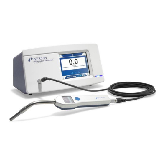
- Page 1 Service Instructions Sensistor Sentrac Hydrogen Leak Detector Catalog No. SEN.122.160, SEN.122.161 From software version nip65en1-05-(1901)
- Page 2 INFICON AB Westmansgatan 47F S-58216 Lingköping Sweden...
-
Page 3: Table Of Contents
5.7 Changing Main PCB .......................... 36 5.8 Changing Front Panel.......................... 38 5.9 Changing Display............................ 41 5.10 Changing LED Lamp .......................... 44 5.11 Changing Speaker .......................... 46 5.12 Changing Rubber Foot ........................... 48 5.13 Open Probe P60 Cover .......................... 49 5.14 Changing Probe PCB with Display ...................... 51 Sensistor Sentrac-Leak Detector-ServiceManual-nip65en1-05-(1901) - Page 4 5.19.2 Changing Probe neck O-ring ...................... 58 5.20 Changing Sensor ............................ 59 5.21 Functional Verification .......................... 60 5.21.1 Functional Verification of Sensitor Sentrac ................. 60 5.21.2 Visual verification of Sensistor Sentrac Battery surface finish ............ 62 6 Software ................................. 63 6.1 Software update............................ 63 6.2 Warning List............................ 63 6.3 Service Screen ............................ 64...
-
Page 5: Safety During Service
Failure to observe the following precautions could result in serious personal injury: WARNING Electrical hazard When service or maintenance is performed on an open instrument, there is a risk of electrical shock. Failure to observe the following precautions could result in damage to the equipment: Sensistor Sentrac-Leak Detector-ServiceManual-nip65en1-05-(1901) 5 / 76... - Page 6 On Customers site, during exchange or maintenance of electronic card, the service personnel must wear an ESD coat and use disposable wristband. NOTICE Check that all relevant legislation and safety standards are complied with before the Sensistor Sentrac is taken into service. 6 / 76 Sensistor Sentrac-Leak Detector-ServiceManual-nip65en1-05-(1901)
-
Page 7: General Information
Read this Manual carefully before putting your instrument into service. When reading, pay particular attention to the WARNINGS, CAUTIONS and NOTICES found throughout the text. 2.1 About this Document This document is only intended for INFICON service personnel working with the Sensistor Sentrac Leak Detector. 2.2 Document History Revision... -
Page 8: Components
3 | Components INFICON 3 Components 3.1 Exploded View (Desktop Model) 8 / 76 Sensistor Sentrac-Leak Detector-ServiceManual-nip65en1-05-(1901) - Page 9 INFICON Components | 3 Sensistor Sentrac-Leak Detector-ServiceManual-nip65en1-05-(1901) 9 / 76...
- Page 10 3 | Components INFICON 10 / 76 Sensistor Sentrac-Leak Detector-ServiceManual-nip65en1-05-(1901)
- Page 11 597-008 KB1016 Probe cable 591-770 Sentrac Main Input Kit 597-009 Torx screw M3x6 MRT 8.8 FZB 591-485 Sentrac Special Tools Kit 597-012 Torx screw M3x4 MRT 8.8 FZB 591-831 Sensistor Sentrac Software 591-964 Installer Sensistor Sentrac-Leak Detector-ServiceManual-nip65en1-05-(1901) 11 / 76...
-
Page 12: Exploded View (Portable Model)
3 | Components INFICON 3.2 Exploded View (Portable Model) 12 / 76 Sensistor Sentrac-Leak Detector-ServiceManual-nip65en1-05-(1901) - Page 13 INFICON Components | 3 Sensistor Sentrac-Leak Detector-ServiceManual-nip65en1-05-(1901) 13 / 76...
- Page 14 3 | Components INFICON 14 / 76 Sensistor Sentrac-Leak Detector-ServiceManual-nip65en1-05-(1901)
- Page 15 Conductive profile 591-829 Sign Serial Number 598-256 KB1114 speaker 591-826 Sign Manufacturing Year 598-255 Speaker gasket 598-205 Screen protector, Sensistor Sentrac 598-436 KB1112 Blue LED 591-827 Sentrac Display Kit 597-005 Environment gasket 598-206 Sentrac Main PCB Kit 597-006 KB1018 headphone cable...
-
Page 16: Exploded View (Hard Neck)
3 | Components INFICON 3.3 Exploded View (Hard Neck) 16 / 76 Sensistor Sentrac-Leak Detector-ServiceManual-nip65en1-05-(1901) - Page 17 Adhesive Display glass 598-260 Adhesive Display glass 598-260 TGF11/P60 Display Glas Kit 597-001 TGF11/P60 Display Glas Kit 597-001 P60 Display Kit 597-000 P60 Display Kit 597-000 Sensistor Sentrac Software 591-964 Sensistor Sentrac Software 591-964 Installer Installer Sensistor Sentrac-Leak Detector-ServiceManual-nip65en1-05-(1901) 17 / 76...
-
Page 18: Interior View (Desktop Model)
3 | Components INFICON 3.4 Interior View (Desktop Model) Description Slot for Expansion Module Slot for SD Card USB Port Communication Port Device Port Speaker Front Panel Instrument Casing LED Lamp Power Supply 18 / 76 Sensistor Sentrac-Leak Detector-ServiceManual-nip65en1-05-(1901) -
Page 19: Interior View (Portable Model)
INFICON Components | 3 Description Display Accessories Plate Main PCB Fuses 3.5 Interior View (Portable Model) Sensistor Sentrac-Leak Detector-ServiceManual-nip65en1-05-(1901) 19 / 76... - Page 20 3 | Components INFICON Description Slot for Expansion Module Slot for SD Card USB Port Device Port Connection Port Speaker Front Panel Instrument Casing LED Lamp Power Supply Display Accessories Plate Main PCB 20 / 76 Sensistor Sentrac-Leak Detector-ServiceManual-nip65en1-05-(1901)
-
Page 21: Troubleshooting
Change probe PCB. Display not lit or is only partially Broken display or probe PCB. Change probe PCB. working. Nothing appears on the display. Display broken or lamp cable loose. Check cable and/or Change Display. Sensistor Sentrac-Leak Detector-ServiceManual-nip65en1-05-(1901) 21 / 76... -
Page 22: Hardware Error Messages
Sensor signal Broken sensor or Change sensor or error, voltage window present baseline voltage broken probe. probe. too low. on screen. Blue level too low, Change sensor LED flashing. below 300 mV. or probe. 22 / 76 Sensistor Sentrac-Leak Detector-ServiceManual-nip65en1-05-(1901) - Page 23 Try to on screen, Blue between probe 2) and/or Probe restart the LED flashing. and instrument. CANL (Pin 3) wire instrument or broken. change the probe cable. If the problem remains contact service. Sensistor Sentrac-Leak Detector-ServiceManual-nip65en1-05-(1901) 23 / 76...
- Page 24 PCB. service on screen, Blue recommended. LED flashing. Probe hardware Red measure Probe PCB Probe PCB Change Probe error, service window present broken. broken. PCB. recommended. on screen, Blue LED flashing. 24 / 76 Sensistor Sentrac-Leak Detector-ServiceManual-nip65en1-05-(1901)
-
Page 25: Service Instructions
On Customer site, during exchange or maintenance of electronic card, the service personnel must wear an ESD coat and use disposable wristband. CAUTION Do not tighten screws with too much torque. This can damage threads on aluminum parts. Sensistor Sentrac-Leak Detector-ServiceManual-nip65en1-05-(1901) 25 / 76... -
Page 26: Safety Equipment, Tools And Consumables
Spanner for notched nuts Part no. 598-438 (LEMO Part no. DCH.91.161.PA) Torx TX10 Torx TX20 Sensor Key Part no. 598-147 Heat Gun Thread locking and adhesive LOCTITE® 2700 or 2701, 2400, 406 and 222 Scissor 26 / 76 Sensistor Sentrac-Leak Detector-ServiceManual-nip65en1-05-(1901) - Page 27 Calibration Leak/Gas 10 ppm H2 in N2 or calibration leak around 5x10⁻⁴ mbarl/s tracer gas (5% H2 in N2) PC (Windows) USB flash drive. Sensistor Sentrac Software Part no. 591-964 Installer USB flash drive. P60 software Installer Part no. 591-964 Display glass adhesive alignment tool Part no.
-
Page 28: Remove The Cover
Check the resistance between the ground pin in the mains socket and the outside of the probe cable connector, should be 9 ohm or lower. If not, check the lock washer on the Probe Connection Port. 28 / 76 Sensistor Sentrac-Leak Detector-ServiceManual-nip65en1-05-(1901) -
Page 29: Remove Accessories Plate
Remove the five screws (A) holding the Accessories Plate (B). Remove the Accessories Plate (B) Assemble Place the Accessories Plate (B). Reinstall and tighten the five screws (A). Reinstall the cover, see Assemble in Remove the Cover [} 28]. Sensistor Sentrac-Leak Detector-ServiceManual-nip65en1-05-(1901) 29 / 76... -
Page 30: Changing Fuses (Desktop Model)
6.3x32 mm Disassemble Disconnect the mains connector. Remove the lid (A) containing the fuses. Remove the fuses. Assemble Install the new fuses. The upper fuse is spare. Reinstall the lid (A) containing the fuses. 30 / 76 Sensistor Sentrac-Leak Detector-ServiceManual-nip65en1-05-(1901) -
Page 31: Changing Power Supply (Desktop Model)
Install the new Power Supply. Connect the power supply cabling according to the drawing below. Reinstall and tighten the two screws, 4 mm, (A) holding the Power Supply. Reinstall the cover, see Assemble in Remove the Cover [} 28]. Sensistor Sentrac-Leak Detector-ServiceManual-nip65en1-05-(1901) 31 / 76... - Page 32 5 | Service Instructions INFICON 32 / 76 Sensistor Sentrac-Leak Detector-ServiceManual-nip65en1-05-(1901)
- Page 33 INFICON Service Instructions | 5 Sensistor Sentrac-Leak Detector-ServiceManual-nip65en1-05-(1901) 33 / 76...
-
Page 34: Changing Battery (Portable Model)
Remove the Battery cabling from the power switch panel and main PCB. Assemble Install the new Battery. Mount the Battery cabling according to drawing below. Reinstall and tighten the four screws (A) holding the Battery. Reinstall the cover, see Assemble inRemove the Cover [} 28]. 34 / 76 Sensistor Sentrac-Leak Detector-ServiceManual-nip65en1-05-(1901) - Page 35 INFICON Service Instructions | 5 Sensistor Sentrac-Leak Detector-ServiceManual-nip65en1-05-(1901) 35 / 76...
-
Page 36: Changing Main Pcb
5.7 Changing Main PCB Part Part no. Consumables Main PCB Sensistor 591-823 Sentrac CAUTION Be very cautions when removing the locking on connector J2 (FFC cable, LCD data, on main PCB). See Drawings [} 71]. 36 / 76 Sensistor Sentrac-Leak Detector-ServiceManual-nip65en1-05-(1901) - Page 37 ð SD-card reader is working. If any of the above tests fails, see Troubleshooting [} 21]. Reinstall the Accessories Plate (B), see Assemble in Remove Accessories Plate [} 29]. Reinstall the cover, see Assemble in Remove the Cover [} 28]. Sensistor Sentrac-Leak Detector-ServiceManual-nip65en1-05-(1901) 37 / 76...
-
Page 38: Changing Front Panel
When function test is performed on an open instrument, there is a risk of electrical shock. CAUTION Be very cautions when removing the locking on connector J2 (FFC cable, LCD data, on main PCB). See Drawings [} 71]. 38 / 76 Sensistor Sentrac-Leak Detector-ServiceManual-nip65en1-05-(1901) - Page 39 Connect all cables between the new Front Panel and the PCB. Pay special attention to J2. Do not use force! Perform a function test before the assembly continues. Ensure the following functions, check that the: Sensistor Sentrac-Leak Detector-ServiceManual-nip65en1-05-(1901) 39 / 76...
- Page 40 (the shield) and one of the screws in the back. The resistance should be 9 ohm or lower. If any of the above tests fails, see Troubleshooting [} 21]. Reinstall the cover, see Assemble in Remove the Cover [} 28]. 40 / 76 Sensistor Sentrac-Leak Detector-ServiceManual-nip65en1-05-(1901)
-
Page 41: Changing Display
Be very cautious when removing the locking on connector J2 (FFC cable, LCD data, on main PCB). See Drawings [} 71]. Disassemble Disconnect the mains connector. Remove the cover, see Disassemble in Remove the Cover [} 28]. Remove the four screws (A) holding the Front Panel (B). Sensistor Sentrac-Leak Detector-ServiceManual-nip65en1-05-(1901) 41 / 76... - Page 42 Perform a function test before the assembly continues. Ensure the following functions, check that the: ð Display is centered in the Front Panel. If not, loosen the screws holding the display and align it. 42 / 76 Sensistor Sentrac-Leak Detector-ServiceManual-nip65en1-05-(1901)
- Page 43 (the shield) and one of the screws in the back. The resistance should be 9 ohm or lower. If any of the above tests fails, see Troubleshooting [} 21]. Reinstall the cover, see Assemble in Remove the Cover [} 28]. Sensistor Sentrac-Leak Detector-ServiceManual-nip65en1-05-(1901) 43 / 76...
-
Page 44: Changing Led Lamp
When function test is performed on an open instrument, there is a risk of electrical shock. CAUTION Be very cautious when removing the locking on connector J2 (FFC cable, LCD data, on main PCB). See Drawings [} 71]. 44 / 76 Sensistor Sentrac-Leak Detector-ServiceManual-nip65en1-05-(1901) - Page 45 (the shield) and one of the screws in the back. The resistance should be 9 ohm or lower. If any of the above tests fails, see Troubleshooting [} 21]. Reinstall the cover, see Assemble in Remove the Cover [} 28]. Sensistor Sentrac-Leak Detector-ServiceManual-nip65en1-05-(1901) 45 / 76...
-
Page 46: Changing Speaker
J2. Carefully tap the screwdriver / locking alternately left/right to loosen the cable from the connector. Do not use force! Remove the Front Panel. Remove the four screws (C) holding the Speaker (D). 46 / 76 Sensistor Sentrac-Leak Detector-ServiceManual-nip65en1-05-(1901) - Page 47 (the shield) and one of the screws in the back. The resistance should be 9 ohm or lower. If any of the above tests fails, see Troubleshooting [} 21]. Reinstall the cover, see Assemble in Remove the Cover [} 28]. Sensistor Sentrac-Leak Detector-ServiceManual-nip65en1-05-(1901) 47 / 76...
-
Page 48: Changing Rubber Foot
2400 Disassemble Remove the screw (A) holding the Rubber Foot (B). Remove the Rubber Foot (B). Assemble Install the new Rubber Foot. Reinstall the screw (A) holding the Rubber Foot. Use thread locking compound. 48 / 76 Sensistor Sentrac-Leak Detector-ServiceManual-nip65en1-05-(1901) -
Page 49: Open Probe P60 Cover
LOCTITE 2400 Lower Part Disassemble Disconnect the Probe from the Sensistor Sentrac. Use a Spanner for notched nut and slightly loosen the C21 connection port nut (A). Remove the two screws and the lock washers (B). Carefully remove the lower part of the Probe handle (C). - Page 50 Measure the resistance between the Probe tip and the C21 connection port. Resistance should be lower than 9 ohm. Re-tension the C21 connection port nut if necessary. Connect the Probe to the Sensistor Sentrac. Start the Probe and make sure that it works properly, check: ð Sensitivity ð...
-
Page 51: Changing Probe Pcb With Display
LOCTITE 2400 display Disassemble Disconnect the Probe from the Sensistor Sentrac. Open the Probe Cover, see Disassemble in Open Probe P60 Cover [} 49]. Remove all cables on the Probe PCB (A). Remove the screw (B) holding the Probe PCB (A). -
Page 52: Changing Probe P60 Display Glass
From dec 2017 glass P60 Disassemble Disconnect the Probe from the Sensistor Sentrac. Open the Probe Cover, see Disassemble in Open Probe P60 Cover [} 49]. Remove all cables on the Probe PCB (A). Remove the screw (B) holding the Probe PCB (A). - Page 53 Firmly apply the OLED-display seal (E) on the Probe Display Glass (C). Use a scalpel and gently remove the center piece in the OLED-display seal. Reinstall the Probe PCB (A). See Assemble in Changing Probe PCB with Display [} 51]. Sensistor Sentrac-Leak Detector-ServiceManual-nip65en1-05-(1901) 53 / 76...
-
Page 54: Changing Probe P60 Led Lamps
591-801 LOCTITE Disassemble Disconnect the Probe from the Sensistor Sentrac. Open the Probe Cover, see Disassemble in Open Probe P60 Cover [} 49]. Remove the LED Lamps connector from the PCB (B). Remove the LED Lamps (A). Carefully tap them out of their sockets. -
Page 55: Changing Probe P60 Button
Part Part no. Consumables Button 598-181 Disconnect the Probe from the Sensistor Sentrac. Disassemble Open the Probe Cover, see Disassemble in Open Probe P60 Cover [} 49]. Remove the screw (B) holding the Probe PCB (A). Loosen the Probe PCB (A). -
Page 56: Changing Probe Neck
LOCTITE 2700 or 2701 Disassemble Disconnect the Probe from the Sensistor Sentrac. Open the Probe Cover, see Disassemble in Open Probe P60 Cover [} 49]. Remove the Probe Sensor (A) from the Probe Neck (B) using a Sensor Key. Remove the Probe PCB (D). -
Page 57: Changing Probe O-Rings
O-ring 8x1 NBR70 591-284 Disassemble Disconnect the Probe from the Sensistor Sentrac. Use a Sensor Key to remove the Probe Sensor Nut (A) from the Probe Neck (B). Use a small slotted screw driver to remove the O-ring inside the Probe Sensor Nut (A). -
Page 58: Changing Probe Neck O-Ring
Consumables O-ring 8x1 NBR70 591-284 Disassemble Disconnect the Probe from the Sensistor Sentrac. Use a Sensor Key to remove the Probe Sensor Nut (A) from the Probe Neck (B). Remove the Probe Neck O-ring (C) from the Probe Neck (B). -
Page 59: Changing Sensor
Part no. Consumables Sensor 590-292 Disassemble Disconnect the Probe from the Sensistor Sentrac. Use a Sensor Key to remove the Probe Sensor Nut (A) from the Probe Neck (B). Pull out the Sensor (C) from the Probe Neck (B). Assemble Insert the new Probe Sensor (C) into the Probe Neck (B). -
Page 60: Functional Verification
Turn the Sensistor Sentrac unit on. Verify that the Hand Probe P60 has the same software version number as stated in the Sensistor Sentrac Software Installer. If not: update the probe via USB cable. Desktop Model: connect the power cable and verify that the plug is properly mounted. - Page 61 ð Connect the headphones ð Listen to verify that audio quality sounds ok. ð Turn down the volume on the Sensistor Sentrac unit to verify that the headphone volume decreases as well. Expose the hand probe to 10 ppm hydrogen. Verify that the bar is increasing.
-
Page 62: Visual Verification Of Sensistor Sentrac Battery Surface Finish
If model is battery operated: ð Charge battery. ð Verify that battery is fully charged. 5.21.2 Visual verification of Sensistor Sentrac Battery surface finish ► Verify that the surface finish looks good. Pay extra attention to the paint finish around the headphone outlet. -
Page 63: Software
Connect the probe to the instrument if the probe-software is to be updated. Double click on the icon on the desktop. Check that the Sensistor Sentrac serial number appear in the COM port window. If the serial number is present, the communication between the computer and the Sentrac is set up. -
Page 64: Service Screen
• Time counter in ms (milli seconds) • A/D value (sensor signal) raw (24 bit) or in mV (depending on settings) • Locating Value • Measuring Value in mV/s (uncalibrated and unconverted) • Data Checksum Output frequency 1-50 Hz. 64 / 76 Sensistor Sentrac-Leak Detector-ServiceManual-nip65en1-05-(1901) -
Page 65: Test Board
Conversion value is set to 1 when ppm is selected as calibration unit and/or measuring Unit. Measure Unit less Measuring Mode or Measuring result value Diagnosis / Service Screen / Signals / Measuring value Sensistor Sentrac-Leak Detector-ServiceManual-nip65en1-05-(1901) 65 / 76... - Page 66 Use full when adjustment have to be done due to environmental circumstances, e.g. accumulation measuring. Displayed measuring unit / Displayed measuring unit value / Calibration Unit Calibrating unit value cc/s Cc/min SCCM 31536000 oz/yr 1112400 66 / 76 Sensistor Sentrac-Leak Detector-ServiceManual-nip65en1-05-(1901)
- Page 67 Measuring displayed unit: Mass flow rate (e.g. g/yr. oz/yr) is selected as Calibration unit and Measuring displayed unit Mass flow rate is selected as Calibration Unit and when normalized flow rate as Measuring displayed unit: Sensistor Sentrac-Leak Detector-ServiceManual-nip65en1-05-(1901) 67 / 76...
- Page 68 Output signal from processed signal signal Locating value Diagnosis / Service Screen / Signals / Locating result Locating value (numeric unit less) Locating graph Diagnosis / Service Screen / Locating Locating result Graph (Graphic diagram) 68 / 76 Sensistor Sentrac-Leak Detector-ServiceManual-nip65en1-05-(1901)
-
Page 69: Settings Reset
See the diagram 1. 6.5 Settings Reset CAUTION All settings affecting measurements will be reset to factory defaults. Click Diagnosis >> Reset >> Settings Click the green Reset button. Wait for the Sensistor Sentrac to restart. Sensistor Sentrac-Leak Detector-ServiceManual-nip65en1-05-(1901) 69 / 76... -
Page 70: Reset To Factory Default
Click Diagnosis >> Reset >> Factory Default. Click the green Reset button. Fill in the service password. Click the green Reset button. Restart the Sensistor Sentrac. 6.7 Reset Calibration To reset an erroneous calibration: Click Diagnosis >> Reset >> Calibration. -
Page 71: Drawings
INFICON Drawings | 7 7 Drawings Sensistor Sentrac-Leak Detector-ServiceManual-nip65en1-05-(1901) 71 / 76... - Page 72 7 | Drawings INFICON 72 / 76 Sensistor Sentrac-Leak Detector-ServiceManual-nip65en1-05-(1901)
- Page 73 INFICON Drawings | 7 Sensistor Sentrac-Leak Detector-ServiceManual-nip65en1-05-(1901) 73 / 76...
-
Page 74: Index
Index INFICON Index 74 / 76 Sensistor Sentrac-Leak Detector-ServiceManual-nip65en1-05-(1901)
Need help?
Do you have a question about the Sensistor Sentrac and is the answer not in the manual?
Questions and answers