
Related Manuals for Delta HYPERSPROUT


Summary of Contents for Delta HYPERSPROUT
- Page 1 HYPERSPROUT™ / HYPERHUB™ SMARTHUB ACCESS POINT INSTALLATION & USER MANUAL Product Name: DEC-H-H-003-10 / DEC-H-H-005-10 Document Revision: A0-01 Date: 20 April 2022...
- Page 2 Neither Delta Energy & Communications, Inc. nor any of its affiliates or subsidiaries shall be responsible or liable for misuse of the information contained herein. If you have any suggestions for improvements or amendments or have found errors in this publication, please notify us.
- Page 3 OBTAINING SERVICE UNDER THIS MANUFACTURER‘S WARRANTY 4.10 STEP 9. CONNECT VOLTAGE TAPPING CABLING GENERAL EXCLUSIONS AND LIMITATIONS OF LIABILITY OPERATIONS & TROUBLESHOOTING POWERING ON OPERATION TROUBLESHOOTING LOCAL GUI LOCAL GUI HYPERSPROUT™/HYPERHUB™ 6.2.1 Set-Up Page 6.2.2 Backhaul Selection 6.2.3 Radio Configuration 6.2.4 Mesh Configuration 6.2.5 Hotspot Configuration 6.2.6...
-
Page 4: Table Of Contents
TABLES FIGURES Table 1: Abbreviations Figure 1: Delta Smart Grid Network (DSGN™) Table 2: Product Specifications Figure 2: Product label located on side of device Table 3: Dos and Don‗ts Figure 3: Product label incl. serial number Table 4: LED Indications... - Page 5 Figure 58: Wi-Fi Status Mesh Figure 29: Connecting sensor cabling Figure 59: Wi-Fi Status Station Figure 1: Delta Smart Grid Network (DSGN™) Figure 30: Representation of sensor & Rogowski cabling Figure 60: System Logs Figure 2: Product label located on side of device...
- Page 6 Delta‘s novel and patented approach brings connective technology wherever there is electricity. In doing so, Delta helps utilities realize the benefits of data analytics to identify and mitigate both technical losses and non-technical losses while aiding in enterprise-wide utility optimization strategies and revenue enhancement.
-
Page 7: Table 1: Abbreviations
1.1.4 deltaLINK™ The Delta Smart Grid Network (DSGN™) couples a Wi-Fi based WWAN mesh with an advanced power metering solution to deliver electrical distribution monitoring and pioneering analytics within a robust and secure, cloud-based network. Delta understands that addressing utility grid management and connectivity concerns mandates the Through this same network, the DSGN™... - Page 8 Acronym Definition Global Positioning System Graphical User Interface hyperSPROUT™ Delta 5G comparable Wi-Fi smarthub hyperHUB™ Delta 5G comparable Wi-Fi access point Internet of Things IP67 Ingress Protection or International Protection Intelligent Transformer Module Light Emitting Diode Long Term Evolution Printed Circuit Board...
-
Page 9: Table 2: Product Specifications
2.1 PRODUCT SPECIFICATION Features Parameters The following table gives an overview of all product specifications. MECHANICAL Dimensions (without antennas) 451 (L) x 350 (W) x 170 (H) mm Table 2: Product Specifications 17.75 (L) x 13.77 (W) x 6.69 (H) in Weight 8.3kgs (18lbs) Features... -
Page 10: Figure 2: Product Label Located On Side Of Device
- Next two digits correspond to the month of manufacturing CCCC - Customer and device-specific, 4-digit code The hyperSPROUT™ smarthub & hyperHUB™ access point serial numbers are on the side of the devices as noted in Figure SSSSS - Serial number of that month 2 and Figure 3. - Page 11 3. SAFETY Rev.A0-01 Rev.A0-01 | 20 | | 21 |...
-
Page 12: Table 3: Dos And Don‗Ts
The hyperSPROUT™ smarthub or hyperHUB™ access point shall not pose any danger when operating under rated • Installation, adjustment, repair, and maintenance must be performed by qualified personnel. - Page 13 This section contains important information on personal protective equipment. Read and understand these instructions before performing any installation procedure. FCC CAUTION STATEMENT FOR MODIFICATIONS CAUTION: Any changes or modifications not expressly approved by Delta Energy and Communication, Inc. could void the user’s authority to operate the equipment 3.3.1 Importance of Personal Protective Equipment To make the workplace safe, you must provide instructions, training, supervision, and procedures.
-
Page 14: Figure 4: Personal Protective Equipment Usage
3.3.3 Personal Protective Equipment Usage Figure 4 provides further information on when to use gloves and/or wear a helmet. DO wear gloves whenever working with your hands (raising ladders, testing wires, or working with wires). DO wear your helmet whenever working with ladders or wire (training, testing, or managing). - Page 15 4. INSTALLATION Rev.A0-01 Rev.A0-01 | 26 | | 27 |...
-
Page 16: Figure 5: Installation Flow
4.1 INSTALLATION FLOW The following steps show the proposed process for installing the hyperSPROUT™ smarthub & hyperHUB™ access point represented in Figure 5: Step 1 Unpack the box Step 2 Verify the package contents Step 3 Install the antennas Step 4... -
Page 17: Figure 7: Package Content
Figure 10: Antenna installation a. Locate the antennas (Item-F). Connect the antenna to the panel mount N-type connector on the hyperSPROUT™ smarthub or hyperHUB™ access point as shown in Figure 10. Tighten it by hand. Figure 8: External dimensions Rev.A0-01 Rev.A0-01... -
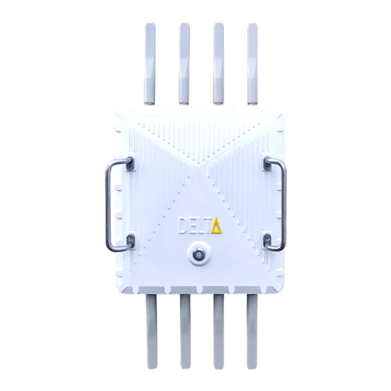
Page 18: Figure 11: Representation Of Antennas After Installation
+ fiber Optic or cellular + Ethernet. A The hyperSPROUT™ smarthub or hyperHUB™ access point may be mounted to an electrical power pole or to a flat surface customer cannot choose both fiber optic and Ethernet. -
Page 19: Figure 15: Installation Of Mounting Bracket On Pole
Figure 17. 4.6.2 Install the Mounting Bracket to a Post or Wall Follow below instructions for mounting the hyperSPROUT™ smarthub or hyperHUB™ access point to a post or wall. Item-G 4 x M10 x 16 Bolt a. Identify the location for installation. Place the mounting bracket against the surface with the flanges facing away from the pole as shown in the following Figure 16. -
Page 20: Figure 18: Device Locking Mechanism
Align the 4 bolts in the back of the hyperSPROUT™ smarthub or hyperHUB™ access point to the 4 slots in the c. After the hyperSPROUT™ smarthub or hyperHUB™ access point bolts are in the mounting bracket slots and locked, mounting bracket. -
Page 21: Figure 21: Representation Of Full Cable Assembly
4.8.1 Connect Cabling to Fiber Cable Directly Follow below instructions when connecting the hyperSPROUT™ smarthub or hyperHUB™ access point to fiber cable. 4.8 STEP 7. CONNECT FIBER BACKHAUL CABLING a. Locate the optical cable mount assembly (Item-B). Feed the end of the optical cable through the optical gland main body (1), optical rubber part (3), and optical gland end cap (4), as shown in Figure 23. -
Page 22: Figure 23: Connecting Fiber Optic Cabling
Connect Cabling to Ethernet 4.9 STEP 8. CONNECT SENSOR CABLING Follow below instructions when connecting the hyperSPROUT™ smarthub or hyperHUB™ access point to Ethernet using an RJ-45 cable. The sensor connector and wire bundle contains 20 individual wires. 10 wires are connected to the temperature sensors a. -
Page 23: Figure 27: Rtd Temperature Sensor
Route and secure the temperature sensor connector cabling from the transformer to the hyperSPROUT™ smarthub d. Connect the sensor connector to the hyperSPROUT™ smarthub as shown in Figure 29. See Figure 30 for final connector. See Figure 30. Note that the hyperHUB™ access point does not include a sensor cabling. - Page 24 Figure 31: Connecting voltage tapping connector to power input c. Twist and tighten the connector by hand to lock the connector in place. d. Route and secure the voltage tapping cable from the hyperSPROUT™ smarthub or hyperHUB™ access point to the transformer secondary. Adjust for length as necessary.