Jasic MIG200PFC Manual
Igbt inverter welder
Hide thumbs
Also See for MIG200PFC:
- Operator's manual (12 pages) ,
- Operator's manual (36 pages) ,
- Manual (70 pages)

Subscribe to Our Youtube Channel
Related Manuals for Jasic MIG200PFC


Summary of Contents for Jasic MIG200PFC
- Page 1 MIG200PFC/MIG250PFC MIG200PFC LCD/MIG250 IGBT INVERTER WELDER Copyright©2022 Shenzhen JASIC Technology Co., Ltd.
- Page 2 JASIC website at www.jasictech.com. Disclaimer Shenzhen JASIC Technology Co., Ltd. solemnly promises that this product is manufactured according to relevant domestic and international standards, and that this product conforms to EN60974-1 International Safety Standard. Patents protect the relevant design scheme and manufacturing technology adopted in this product.
-
Page 3: Table Of Contents
Contents 1. Safety precautions ......................5 1.1. General safety ........................ 5 1.2. Other precautions ......................8 2. Description of symbols ....................... 9 3. Product overview ......................11 4. Technical parameters ....................... 13 5. Installation ........................16 5.1. External interface description ..................16 5.2. - Page 4 For your safety, please read this manual carefully before installing and operating this JASIC equipment. Pay extra attention to all content marked with " ". All operations must be carried out by professional, suitably qualified persons! Page 4...
-
Page 5: Safety Precautions
1. Safety precautions 1.1. General safety SAFETY INSTRUCTION These general safety norms cover both arc welding machines and plasma cutting machines unless otherwise noted. It is important that users of this equipment protect yourselves and others from harm or even death. - Page 6 Arc rays——May injure the eyes and burn the skin. The arc rays from all processes produce intense, visible and invisible (ultraviolet and infrared) rays that can burn eyes and skin. ·Wear an approved welding helmet fitted with an appropriate shade of filter lens to protect your face and eyes when working or watching.
- Page 7 If you still do not fully understand or cannot solve the problem after reading the instructions in this manual, you should contact the supplier or JASIC's service center immediately for professional help.
-
Page 8: Other Precautions
1.2. Other precautions Warning! Location The machine should be located in a suitable position and environment. Care should be taken to avoid moisture, dust, steam, oil or corrosive gases. Place on a secure level surface and ensure that there is adequate clearance around the machine to ensure natural airflow. -
Page 9: Description Of Symbols
2. Description of symbols Warning! Read the Manual Electric shock risk warning WEEE tag Current unit "A" Wire feed speed unit "m/min" Thickness of welding base metal "mm" Voltage unit "V" "Inductance" of MIG / "Arc force" of MMA MIG burn back time unit "ms" Overheat protection indicator Overcurrent protection indicator VRD function indicator... - Page 10 Welding wire diameter MIG/Lift TIG 2T operation MIG/Lift TIG 4T operation MIG push torch MIG push-pull torch MIG spool torch Other function switching Remote control function Synergic MIG function Inching function Gas check function Page 10...
-
Page 11: Product Overview
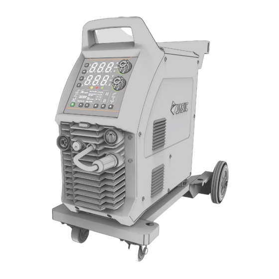
3. Product overview HD digital screen version Touchless LCD version This series of GMAW welder features rich functions, easy operation, advanced technology, excellent performance and high quality. It supports three welding modes, i.e. DC MIG, DC MMA and Lift TIG, and can be widely used for welding various metal materials. In DC MIG, the machine has the "Synergic"... - Page 12 ◆ MMA hot start function: Makes MMA arc ignition easier and more reliable. ◆ Lift TIG is controlled by the torch switch. ◆ On-demand fan: Prolongs the fan lifespan and reduces internal dust accumulation. ◆ Parameters are automatically saved before shutdown, and the settings are restored after starting again.
-
Page 13: Technical Parameters
4. Technical parameters Item Unit MIG250 Model MIG250 Input voltage 230±15% Input frequency 50/60 45.5@MIG Rated input current 40.0@TIG (AC230V) 45.5@MMA 10.5@MIG Rated input power 9.2@TIG (AC230V) 10.5@MMA Output voltage range 11~30 (MIG) Wire feed speed range (MIG) m/min 2~18 Output current range 30~250 (MIG) - Page 14 Dimensions L*W*H 920*480*755 Net weight 41.3 Overall total weight 53.8 Idle state power <50 Characteristics CC/CV Pollution level Level 3 Item Unit MIG250PFC/MIG200PFC Parameters Model MIG250PFC MIG200PFC Input voltage 95~265 95~265 Input frequency 50/60 50/60 33.6@MIG 24.5@MIG Rated input current 26.4@TIG 19.3@TIG...
- Page 15 Arc force current range 0~100 0~100 Hot start current range 0~60 0~60 No-load voltage VRD voltage 26.5@MIG 24@MIG Rated operating voltage 20@TIG 28.8@MMA 18@TIG 27.2@MMA Efficiency (%) >80% >80% Duty cycle (%) Power factor 0.99 0.99 Insulation class Protection class IP23S IP23S Dimensions L*W*H...
-
Page 16: Installation
5. Installation Warning! All connections shall be made after the power supply is turned off. Warning! Electric shock may cause death; after power failure, there is still a high voltage on the equipment, do not touch the live parts on the equipment. Warning! Incorrect input voltage may damage the equipment. -
Page 17: Power Installation
5.2. Power installation Warning! The electrical connection of equipment shall be carried out by suitably qualified personnel. Warning! All connections shall be made after the power supply is turned off. Warning! Incorrect voltage may damage the equipment. 1) Ensure the input voltage value is within the specified input voltage range. 2) Ensure that the power switch is turned off. -
Page 18: Mig Welding Torch And Earth Cable Connection
5.3. MIG welding torch and earth cable connection Pay attention to the polarity of the wiring before MIG. Generally, there are two wiring methods for DC welder: DCEP and DCEN. DCEP: The polarity changeover connector is connected to the positive polarity, and the workpiece is connected to the negative polarity;... - Page 19 the other end to the gas regulator outlet, and secure it with a clamp. 5.3.2 DCEN 1) Ensure that the welder power switch is turned off. 2) Insert the torch plug into the central socket on the front panel of the welder and tighten it clockwise.
-
Page 20: Mma Electrode Holder And Earth Cable Connection
5.4. MMA electrode holder and earth cable connection (MMA wiring diagram: DCEP) (MMA wiring diagram: DCEN) Pay attention to the polarity of the wiring before MMA. Generally, there are two wiring methods for DC welder: DCEP and DCEN. DCEP: The electrode holder is connected to the positive polarity, and the workpiece is connected to the negative polarity;... -
Page 21: Lift Tig Welding Torch And Earth Cable Connection
1) Ensure that the welder power switch is turned off. 2) Insert the cable plug with electrode holder into the corresponding socket on the front panel of the welder and tighten it clockwise. 3) Insert the cable plug with earth clamp into the corresponding socket on the front panel of the welder and tighten it clockwise. -
Page 22: Wired Handheld Remote Controller/Foot Pedal Controller Connection (Optional)
in order to reduce the voltage drop due to the cable length. 5.6. Wired handheld remote controller/foot pedal controller connection (optional) (Wiring diagram of wired remote controller) Insert the 9-pin aviation plug of the handheld remote controller/foot pedal controller directly into the corresponding 9-pin aviation socket of the machine. -
Page 23: Installation Of Wireless Receiver Module (Optional)
5.7. Installation of wireless receiver module (optional) (Installation of wireless receiver module) 1) Remove the wireless remote controller plug cover shown in the above left figure (a). Refit into the wireless receiver module shown in the above right figure (b). 2) Remove the screws on the left side cover of the machine and remove the side panel. -
Page 24: Control Panel
6. Control panel The operation panel for this series of models supports HD digital screen and touchless LCD screen, which can be selected or replaced as needed, without needing to replace the main program of the welder. 6.1. HD digital screen 6.1.1 Overview a.Parameter display a b.Parameter display b... - Page 25 a. Parameter display a "Parameter display a" is used to display the current, welding speed, plate thickness and error code. 1) When not welding, the preset value of current parameter will be displayed. If no operation is performed for a long time, the default parameters are displayed. 2) When welding, the actual output current value is displayed.
- Page 26 d. Selection of MIG welding wire type and gas 1) In MIG mode, press the keys to select the welding wire type and gas. 2) If the corresponding indicator is on, it indicates that the welding wire type and gas has been selected.
- Page 27 g. Selection of push/push-pull/spool torch In MIG mode, press the corresponding function switching key to select the push torch or spool torch. 1) If the indicator is on, it indicates that the MIG is in push torch state. 2) If the indicator is on, it indicates that the MIG is in push-pull torch state.
- Page 28 After successful pairing, the parameters can be adjusted by the wireless remote controller. (2) Disconnect wireless remote controller After the remote controller has been successfully paired, press and hold the remote control function key on the panel or the pairing key on the wireless remote controller for 2s, and the connection of the wireless remote controller will be disconnected.
- Page 29 valve is open; if the indicator is off, it indicates that the gas check function is disabled and the gas valve is closed. Note: The gas check function automatically stops after 20s to avoid gas waste. l. Parameter adjustment knob A 1) In MIG mode, if the "Synergic"...
- Page 30 professional maintenance personnel of the company. o. VRD function indicator 1) The VRD function only works in MMA mode. When the VRD function is not enabled, the VRD indicator is off. 2) When the VRD function is enabled and no welding is performed, the VRD indicator displays green , indicating that the VRD function is normal.
- Page 31 X and Y represent the 20th and 21st digits/letters of the digital barcode 8.XY respectively X and Y represent the 22nd and 23rd digits/letters of the digital barcode 9.XY respectively The 12th-19th digits in the digital barcode are the company's internal fixed numbers, which are not displayed in the window.
- Page 32 6.1.4 Welding engineer mode function The Welding Engineer Mode function allows users to set/modify the default parameters /functions as follows: 1) Press and hold "Parameter Adjustment Knob A" for 5s in startup state. 2) After pressing and holding the "Parameter Adjustment Knob" for 2s, the machine will count down from 3s;...
- Page 33 2)If the "Welding Mode" is MIG, set the MIG post-flow time, with range of 0-5.0, accuracy of 0.5, and unit of seconds. 2) If the "Welding Mode" is Lift TIG, set the Lift TIG post-flow time, with range of 0-10.0, accuracy of 0.5, and unit of seconds.
-
Page 34: Touchless Lcd Screen
6.2. Touchless LCD screen 6.2.1 Overview (LCD screen operation panel) LCD screen Display all human-computer interaction information Press the key to directly return to Home page. Home key This key is invalid on Home page. Adjust most of the parameters and select options on the LCD screen: Master The knob can be used to adjust all parameters, switch among pages or encoder... - Page 35 6.2.2 LCD screen functions 1. Home page The Home page includes the following content: 1) There are 6 options in this page, which are displayed in order from: Synergic MIG (SynMIG), MIG, MMA, Lift TIG, Settings and User Manual. When entering the Home page, the SynMIG is selected by default.
- Page 36 4) The connection symbol on the top right indicates the connection state of welder with wireless remote controller. 6.2.3 Welding mode selection and entrance In the Home page, rotate the master encoder to select the welding mode, and press the master encoder to enter the mode.
- Page 37 SynMIG page MIG page Page 37...
- Page 38 MMA page Lift-TIG page When not welding, the working page displays the preset welding parameters; when welding, it displays the actual current and voltage values. During welding, the user can press the master encoder to select parameters and rotate the encoder to set parameters, and then the screen will enter the corresponding page and display the parameters according to your selection;...
- Page 39 6.2.5 Selection and adjustment of welding parameters The master encoder can switch and adjust all parameters. If the numbers or options on the LCD screen display green, it indicates the parameter can be adjusted with the master encoder; if they display gray, it indicates the parameter cannot be adjusted. 1.
- Page 40 time Inductance -10~+10 Burn back 10.0~20.0V voltage Arc force 0~100A current parameters Hot start 0~60A current Pre-flow 0~5.0S time Post-flow Lift TIG 0~10.0S time parameters Current downslope 0~5.0S time To select parameters, the user needs to first rotate the encoder to select "Parameter Settings"; then press the encoder to enter the "Parameter Settings"...
- Page 41 6.2.6 Storage channel function The storage channel function is only available in the LCD screen version. HD digital screen does not support such function. The storage channel is used to store the four groups of welding parameters in the current welding mode. All four welding modes are provided with four storage channels.
- Page 42 Note: Due to the limited area of the LCD screen, only the most commonly used welding parameters are displayed. At this time, you can save the set welding parameters to the channel, or call/delete the existing welding parameters in the channel. Press the master encoder to perform save/read/delete operation of the current channel, as shown in the following figure: 1)...
- Page 43 2) Read: Read the welding parameters saved in the channel and have parameters displayed on the LCD screen. 3) Delete: Reset all parameters in the channel to the default values. 6.2.7 Inching/gas check function In the SynMIG or MIG page of LCD screen, the user can select the option on the operation page to enter the "Inching"...
- Page 44 Gas check Note: 1) To use "Inching" function, the master encoder shall be pressed and held; if the encoder is released, the inching function will stop. 2) To use "Gas Check" function, press the master encoder once to start gas check, and press it again to stop gas check;...
- Page 45 For special functions, please refer to the following section: 2. Control Mode The wireless remote function includes three options: Wireless Remote, Wired Remote, and Local. Page 45...
- Page 46 (1) Wireless Remote Wireless pairing connection The optional wireless remote control devices for this series of models include wireless foot pedal controller and wireless handheld remote controller. After entering "User Parameter Setting", set the remote control function to "Wireless Remote" and return to "User Parameter Setting";...
- Page 47 Disconnecting wireless remote control device Select "Local" for the wireless remote control function to disconnect the wireless remote control device. (2) Wired Remote The optional wired remote control devices for this series of models include wired foot pedal controller and wired handheld remote controller. Set the remote control function to "Wired Remote", and the connected wired remote control device can be used.
- Page 48 as operation mode, welding torch, etc. functions, please refer to Section 6.1.3. ① The welding parameters in all welding modes; Factory reset For the default values of all welding ② The function options in all welding modes, such parameters and as operation mode, welding torch, etc.
- Page 49 6. System Information The "System Information" on the "Settings" page includes: Rated welder current, LCD software version, welder software version and barcode information. 6.2.9 Main menu page The "Main Menu" function is unique to the LCD screen. In "Main Menu", the user can view the User Manual, Accessory Guide, Alarm and Solutions of the welder.
- Page 50 6.2.10 Other functions and operations 1. Protection/malfunction display In case of protection/malfunction, the welder will stop working immediately, and the LCD screen will display the protection or malfunction code. At this time, the welder cannot work or operate until the protection or malfunction is released. Note: The above figure is an example of overheat protection.
- Page 51 automatically; · The overcurrent protection cannot be automatically released; unless the welder is turned off and restarted. If the overcurrent protection remains after restarting, please contact the sales department of the company. 2. VRD function display In MMA mode, the VRD function can be enabled or disabled: if VRD is enabled, the VRD icon will be displayed;...
-
Page 52: Welding Function Operation
7. Welding function operation Warning! Before turning on the power supply make sure that the equipment is disconnected to the output. Otherwise, an unexpected arc may be started when the power is turned on. This can cause damage to the work piece and to personnel. - Page 53 7.1.2 Select MIG mode HD digital screen: 1) Press the "Welding Mode Selection" key to select MIG mode. 2) Use the corresponding function switching key to select the welding type, wire diameter, operation method and welding torch type. 3) Enable/disable the "Synergic" function. 4) Use "Parameter Adjustment Knob A/B"...
- Page 54 (Setting wire feed speed and voltage) (Setting inductance) (Setting burn back) 1) Use "Parameter Adjustment Knob A" to set the "Wire Feed Speed". 2) Use "Parameter Adjustment Knob B" to set the "Welding Voltage". 3) Press "Parameter Adjustment Knob B" to switch display of "Welding Voltage", "Welding Inductance", and "Burn Back Time"...
- Page 55 MIG250PF MIG200P MIG250 Wire feed 2~14 2~12 speed (m/min) Welding voltage 11~25 11~23 Inductance -10~10 -10~10 Burn back time 0~800 0~800 (ms) Burn back 10.0~20. 10.0~20.0 10.0~20.0 voltage (V) 7.1.4 Set welding parameters with "Synergic" enabled HD digital screen: (Setting welding current) (Setting wire feed speed) (Setting plate thickness) 1) Press "Parameter Adjustment Knob A"...
- Page 56 1) Both the "Parameter Adjustment Knob A" and the master encoder can be used to adjust the welding current. When the current is adjusted, the wire feed speed and plate thickness also change with it. 2) The "Parameter Adjustment Knob B" can be used to adjust the welding voltage. When the voltage is adjusted, the arc length also changes with it.
- Page 57 "Welding Voltage". For details about panel operations, see sections 7.12-7.14. NOTE! If the digital torch is used, select the welding torch type of "Spool torch". The parameters can be adjusted by both the adjustment knobs on the operation panel and adjustment keys on the digital torch.
- Page 58 (Select spool torch on HD digital screen) (Select spool torch on LCD screen) The welder can select push-pull torch in both "Non-synergic" and "Synergic" MIG modes. 7.1.6 Start welding Description of MIG 2T/4T operation 2T operating mode 4T operating mode Step 1: Press the torch trigger to Step 1: Press the torch trigger for the first start welding.
- Page 59 Welding sequence of MIG 2T/4T operation Mode Schematic diagram Pre-flow Torch trigger No-load voltage Gas supply Anti-stick time Post-flow supply time Output terminal voltage Wire feed Slow wire feed Welding current Welding Torch trigger Pre-flow No-load voltage Gas supply Anti-stick time Post-flow supply time Output terminal voltage...
-
Page 60: Mma Operation
7.1.7 Turn off the power supply after welding The power switch is located on the rear panel of the machine and set it to the "OFF" position. After a time delay, the panel indicator is off and the welder stops working. 7.2. - Page 61 3) Hot start current: Stronger hot start current is conducive to arc start and reduces sticking between the welding electrode and workpiece during arc start. Setting range of "Arc Force" and "Hot Remarks Start Current" Parameter Name MIG250PF MIG200PFC HD digital MIG250 LCD screen screen Adjustable on Enter the Arc force...
-
Page 62: Lift Tig Operation
Hot start Adjustable on Settings" 0~60A current user menu page to adjust 7.2.4 Start welding During DC welding, the heat on the positive and negative polarities of the welding arc is different. When welding using DC power supply, there are DCEP and DCEN connections. The DCEP connection refers to the welding electrode connected to the positive polarity of the power supply and the workpiece connected to the negative polarity of the power supply. - Page 63 (Select Lift TIG mode in HD digital screen) (Select Lift TIG mode in LCD screen) 7.3.3 Set welding parameters For HD digital screen, use the "Parameter Adjustment Knob A" to set the "Welding Current"; for LCD screen, use the master encoder to set the "Welding Current"; (as shown in above figure) Choose the appropriate welding current, tungsten electrode and shielding gas flow based on the actual situation.
-
Page 64: Standby
Short circuit Arcing (LIft TIG mode) NOTE! When starting the arc if the short-circuit time exceeds 2 seconds the welder turns off the output current. Lift the welding torch clear of the work piece. Restart the process as above (7.3.2) to start the arc again. NOTE! During welding, if there is short circuit between tungsten electrode and the work piece, the welder will immediately reduce the output current;... -
Page 65: Functions And Use Of Wireless/Wired Remote Controller
operations for a long time. The default standby response time is 10 minutes. 2) Exit standby state: In standby state, any operation on the welder will cause it to exit standby state, including welding, key/knob operation, pressing the torch trigger, or operating the paired and valid remote controller, etc. -
Page 66: Maintenance
8. Maintenance Warning! The following operation requires sufficient professional knowledge on electric aspects and comprehensive safety knowledge. Make sure the input cable of the machine is disconnected from the electricity supply and wait for 5 minutes before removing the machine covers. Please note: The following should only be carried out by an authorised electrical technician. -
Page 67: Troubleshooting
9. Troubleshooting Warning! Before arc welding machines are dispatched from the factory, they have already been checked thoroughly. The machine should not be tampered with or altered. Maintenance must be carried out carefully. If any wire becomes loose or is misplaced, it maybe potentially dangerous to user! Only professional maintenance personnel should repair the machine! Ensure the power is disconnected before working on the machine. - Page 68 · The welding wire is of poor quality Please contact the maintenance Other malfunction personnel of Shenzhen JASIC Technology Co., Ltd. Elimination of general problems in MMA Symptom Reasons Troubleshooting When the temperature is too low, leave The ambient the machine to operate for a while.
- Page 69 · Use different power cords to connect Serious interference equipment that could seriously interfere from other electrical with welder. equipment. Please contact the maintenance Other malfunction personnel of Shenzhen JASIC Technology Co., Ltd. Page 69...
-
Page 70: Alarm And Solutions
9.2. Alarm and solutions Error Category Possible cause Countermeasure code Continuously Restart the welder. If it is still in overcurrent output the protection, contact the after-sales department Overcurrent maximum capacity of the company. protection current of the welder Turn off and restart the machine. If this the alarm cannot be eliminated and the grid voltage remains too low, check the power grid Undervoltage... -
Page 71: Common Mig Malfunction
9.3. Common MIG malfunction When the welding conditions do not meet the requirements, the phenomena described in the following table will occur: Table 9.3 Common MIG malfunction Unsuitable Unsuitable Welding Result Result Welding Condition Condition The arc is unstable, The arc is too long and the resulting in welding fusion spatter increases. -
Page 72: Packaging, Transportation, Storage And Waste Disposal
10. Packaging, transportation, storage and waste disposal 10.1. Transportation requirements In the process of handling the equipment, it should be handled with care, and should not be dropped or severely impacted. Avoid moisture and rain during transportation. 10.2. Storage conditions Storage temperature:-25 ℃... -
Page 73: After-Sales Service
Perform preliminary troubleshooting or record malfunction according to the common malfunction analysis and solution checklist. To repair or replace the device, contact a local dealer. Please use accessories or consumables provided by Shenzhen JASIC Technology Co., Ltd. The warranty of this machine is subject to the date of sale on the warranty card or sales contract. -
Page 74: Appendixes
Appendixes Appendix 1: Wiring diagram Wiring diagram 1 - MIG200PFC/MIG250PFC Page 74... - Page 75 Wiring diagram 2 - MIG250 Page 75...
-
Page 76: Appendix 2: List Of Common Spare Parts
Appendix 2: List of common spare parts List of spare parts Material Code SN Name Quantity MIG200PFC MIG250PFC MIG250 HD digital display 51001082 51001082 51001082 board LCD screen 51001159 components Wireless receiver 51001250 51001250 51001250 module Euro MIG welding 51000333... - Page 77 17 Inverter board 10083048 10083048 10083048 22 Large fan 51000334 51000334 51000334 PFC board (plus) 51001142 51001140 PFC board 51001769 51001807 (standard) Rectifier filter board 28 Small fan 10044009 51001180 10044009 30 Gas valve 10007277 10007277 10007277 33 Power switch 10084286 10084286 10084286...
-
Page 78: Appendix 3. Packaging And Parts
9-16mm 10057339 1 (plus) Φ6.5x3 (without fastening nut Waterproof socket 10038768 and washer) (standard) Wire feed roller 0.6-0.8 (V type) 10016540 Standard parts of MIG200PFC Quantity Classification Name Material code Unit Earth clamp 300A-16mm2-DKJ35-50(3M) 10043956 MIG welding torch MB-15(3M) 51000535... - Page 79 Page 79...
Need help?
Do you have a question about the MIG200PFC and is the answer not in the manual?
Questions and answers