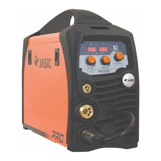
Jasic MIG Series User Manual

Jasic MIG Series User Manual

Mig/mag inverter welder
Hide thumbs Also See for MIG Series:

Advertisement

Quick Links

MIG/MAG inverter welder
USER'S MANUAL
Original instructions
MIG90\MIG100\M100\M110\MIG120\MIG130\MIG140(N2A1 Series)
& MIG90\MIG100\MIG120(N2A2 Series)
SHENZHEN JASIC TECHNOLOGY CO.,LTD.
NO.3, QINGLAN 1ST ROAD, PINGSHAN DISTRICT, SHENZHEN, P. R. CHINA
BJ 2020
1

Advertisement

Table of Contents
loading
Need help?

Need help?

Do you have a question about the MIG Series and is the answer not in the manual?

Questions and answers

Subscribe to Our Youtube Channel

Summary of Contents for Jasic MIG Series

  • Page 1 MIG/MAG inverter welder USER’S MANUAL Original instructions MIG90\MIG100\M100\M110\MIG120\MIG130\MIG140(N2A1 Series) & MIG90\MIG100\MIG120(N2A2 Series) SHENZHEN JASIC TECHNOLOGY CO.,LTD. NO.3, QINGLAN 1ST ROAD, PINGSHAN DISTRICT, SHENZHEN, P. R. CHINA BJ 2020...
  • Page 2 : 1. Jasic make every effort to achieve the full accuracy and data integrity of this manual’s content; Jasic assume no liability and responsibility for any nonconforming operation to this manual.
  • Page 3 SAFETY INSTRUCTIONS The welding devices conform to international safety standards. Safety is an important issue in equipment design and manufacturing. There are, however, always certain hazards involved in using welding equipment. Therefore, to ensure your personal safety and the safety of your working environment, carefully read the safety instructions below and respect them.
  • Page 4 immediately as they can be lethal and may cause electrocution or fire.  Remember that the cable, plugs and other electric devices may be installed or replaced only by an electrical contractor or engineer authorized to perform such operations.  Turn off the welding machine when it is not in use. Fume ——...
  • Page 5 with adequate fire fighting equipment.  In special welding jobs, be prepared for hazards such as fire or explosion when welding container type work pieces.  Never direct the spark spray or cutting spray of a grinder toward the welding machine or flammable materials.
  • Page 6 2 Key points of safety This welding machine is furnished with overvoltage, overcurrent and overheating protection circuit. When electric grid voltage, output current and interior temperature exceed the setting standard, welding machine will stop automatically ; but overuse(such as overvoltage) may damage welding machine, therefore, you should pay attention to the following points:...
  • Page 7 Warning When output exceed duty cycle grade, the temperature in equipment will rise up, at this moment, the protective circuit will work and disconnect the power source output, the equipment will not resume work until it cools to normal temperature. Notice: Persistent overload may damage welding power source.
  • Page 8 possible throughout their length. Straighten any loops in the cables. This minimizes your exposure to harmful magnetic fields, which may interfere with a pacemaker, for example. 5) Do not wrap the cables around the body. 6) In environments classified as dangerous, only use S-marked welding devices with a safe idle voltage level.
  • Page 9 4) Don’t conduct the welding in the dust area or under the environment of corrosive gas. 5) Don’t conduct the gas shielded welding work under the environment of stronger air flow. 6) Inclination between placement of welding machine and horizontal plane is ≤10°. 7) The welding power source is not suitable for use in rain or snow, although it can be used and stored outdoors.
  • Page 10 7 Other information about the machine: 1、 Cooling method: fan cooling Shoulder Strap 2、 for moving 3、 Characteristics of welding machine: flat characteristic Only qualified personnel can operate this machine! Please use welding protection appliances approved by national safety  supervision department.
  • Page 11 When trouble strikes in installation and operation, please resort to  this manual for according contents. If you are still in lost, or you still cannot solve the problem, please  contact the JASIC dealer or the service center for professional support.
  • Page 12 GRAPHIC SYMBOLS AND INDICATIONS Warning in operation Read this operation manual carefully before use It’s forbidden to dispose electric waste with other ordinary waste. Please take care of our environment. Do not use outdoors Insulation class Symbol of Metal inert and active gas welding Single-phase static frequency converter-transformer rectifier Symbol of single-phase AC power supply and rated frequency Can be used in the environment which has high risk of electric shock.
  • Page 13: Table Of Contents

    TABLE OF CONTENTS 1. INTRODUCTION........................1 1.1 How To Use This Manual....................1 1.2 Receipt Of Equipment......................1 1.3 Description........................... 1 1.4 User Responsibility......................1 1.5 Packaged Items........................1 1.6 Specifications ........................2 2. INSTALLATION........................4 2.1 Environment and Location....................4 2.2 Input Power Connection.....................5 2.3 Features..........................7 2.4 Wire Loading and Threading...................8 3.
  • Page 14: Introduction

    This equipment or any of its parts should not be altered from standard specification without prior written approval of JASIC. The user of this equipment shall have the sole responsibility for any malfunction which results from improper use of unauthorized modification from standard specification, faulty maintenance, damage or improper repair by anyone other than appropriately qualified persons approved by JASIC.
  • Page 15: Specifications

    1.6 Specifications N2A2 Series machines N2A1 Series machines Items MIG90 MIG100 MIG120 MIG90 MIG100 M100 M110 MIG120 MIG130 MIG140 Rated input Single-phase AC110~AC120V Single-phase AC220~AC240V 50Hz/60Hz voltage 50Hz/60Hz Rated input power (KVA) Steel 0.6\0.8\ Applicable wire (mm) Steel flux cored 0.8\0.9 Power 0.68 factor(COSφ)
  • Page 17: Installation

    2. INSTALLATION Read this entire installation section before you start installation. 2.1 Environment and Location Safety Precautions Do not attempt to use this equipment until you have thoroughly read all installation, operating and maintenance information supplied with your equipment. They include important safety precautions and detailed operating and maintenance instructions.
  • Page 18: Input Power Connection

    other electronic equipment. These problems may be the result of radiated interference. Proper grounding methods can reduce or eliminate this. Radiated interference can develop in the following ways 1.Direct interference from welder power source 2.Direct interference from the welding leads 3.Direct interference radiated from feedback into power lines 4.
  • Page 19 The mains supply voltage should be within ±5% of the rated mains supply voltage. Too low a voltage may cause poor welding performance. Too high a supply voltage will cause components to overheat and possibly fail. CODE REQUIREMENTS FOR ELECTRICAL INPUT CONNECTIONS This welding machine must be connected to a power source in accordance with applicable electrical codes.
  • Page 20: Features

    2.3 FEATURES [1] Front Panel Layout Description MIG/MAG WITH GAS SERIES MACHINES MIG/MAG WITH GAS LESS SERIES MACHINES 1.Negative Welding Terminal(-) 3.MIG Torch Polarity Lead 5.Work LED 7.MIG Torch 2.Positive Welding Terminal(+) 4. Synergic knob 6.Work Lead 8.Gas IN 9.FAN 10.Power Input Cable 11.Power Switch 12.Power LED...
  • Page 21: Wire Loading And Threading

    2.4 Wire Loading and Threading Turn machine power switch to the OFF(“0”)position before working inside the wire feed enclosure. Make sure that the wire feed drive roll and the contact tip of the gun match the diameter and type of wire used.
  • Page 22 WARNING When feeding the welding wire through the gun, the drive roll, the gun connector block and the gun contact tip are always energized relative to work and ground. WIRE STICKOUT 10. Remove the contact tip and nozzle from the gun. 11.
  • Page 23: Operation

    3. OPERATION Read and understand this entire section before operating your machine. Safety Precautions Do not attempt to use this equipment until you have thoroughly read all operating and maintenance manuals supplied with your equipment and any related welding machine it will be used with. They include important safety precautions, operating and maintenance instructions and parts lists.
  • Page 24: Installation Setup For Mig With Gas Less

    3.1 Installation Setup For MIG with Gas less [1] Switch the Power Source ON/OFF switch located on the rear of the power source to the OFF position. [2] Connect the weld power cable to the Negative socket and tighten it. [3] Connect the earth cable plug into the Positive socket and tighten it.
  • Page 25 [5]Fit the correct sized Knurled Driver roller [6]Place wire onto spool holder(spool retaining for Gas Less Flux Cored wire nut is top thread) Feed the wire through the inlet guide tube on to the drive roller [10]Remove the gas nozzle [7-9]Close down the top roller bracket and [13/14]Fit the correct size and contact tip from the...
  • Page 26: Installation Setup For Mig With Gas

    3.2 Installation Setup For MIG with Gas [1] Insert the earth cable plug into the negative socket on the front of the machine and tighten it. [2] Connect the weld power cable to the positive socket. IMPORTANT: When connecting the torch be sure to tighten the connection. A loose connection can result in the connector arcing and damaging the machine and gun connector.
  • Page 27 [5] Fit the correct sized Knurled Driver roller [6] Place wire onto spool holder(spool retaining nut is top thread) Feed the wire through the inlet for Gas wire or Solid Hard wire guide tube on to the drive roller Remark:V Groove Drive Roller for Steel Wire U Groove Drive Roller for Soft Wire [10] Fit the correct size [12] Fit the gas...
  • Page 28 GMAW/FCAW Basic Welding Technique Two different welding processes are covered in this section (GMAW and FCAW), with the intention of providing the very basic concepts in using the MIG mode of welding, where a welding gun is hand held, and the electrode (welding wire) is fed into a weld puddle, and the arc is shielded by an inert welding grade shielding gas or inert welding grade shielding gas mixture.
  • Page 29 situation it is recommended to open the cylinder valve, set the flow rate to 8-10L/min, close the cylinder valve and check after a minimum of 15minutes. [5] If there is a gas loss then check all connectors and clamps for leakage by brushing or spraying with soapy water, bubbles will appear at the leakage point.
  • Page 30: Basic Mig Welding

    For practicing MIG welding, secure some pieces of 1.5mm or 2.0mm mild steel plate 150X 150mm. Use 0.8mm flux cored gas less wire or a solid wire with shielding gas. 3.3 Basic MIG Welding Good weld quality and weld profile depends on gun angle, direction of travel, electrode extension (stick out), travel speed, thickness of base metal, wire feed speed (amperage) and arc voltage.
  • Page 31 Travel angle is the right to left angle relative to the direction of welding. A travel angle of 5°- 15° is ideal and produces a good level of control over the weld pool. A travel angle greater that 20° will give an unstable arc condition with poor weld metal transfer, less penetration, high levels of spatter, poor gas shield and poor quality finished weld.
  • Page 32: Travel Speed

    3.4 Travel Speed Travel speed is the rate that the gun is moved along the weld joint and is usually measured in mm per minute. Travel speeds can vary depending on conditions and the welders skill and is limited to the welders ability to control the weld pool.
  • Page 33: Maintenance

    MAINTENANCE 4.1 Safety Matters Risk of injury from electric shock! Cleaning machines that are not disconnected from the mains can lead to serious injuries! ◎ Disconnect the machine completely from the mains. ◎ Remove the mains plug. ◎ Wait for 5 minutes until the capacitors have discharged. ELECTRIC SHOCK can kill ◎...
  • Page 34: Periodic Check

    3) In order to ensure the high performance of the machine, please choose components provided or recommended by Shenzhen Jasic Technology Co., Ltd. when replacing components. Table 4-1: Daily checking of the welding machine Items Checking requirements Remarks Whether any of the components are damaged or loosely connected;...
  • Page 35: Customer Assistance Policy

    We respond to our customers based on the best information in our possession at that time. JASIC Electric is not in a position to warrant or guarantee such advice, and assumes no liability, with respect to such information or advice, We expressly disclaim any warranty of any kind, including any warranty of fitness for any customer’s particular purpose, with respect to such information or advice.
  • Page 36: Troubleshooting

    JASIC Electric is a responsive manufacturer, but the selection and use of specific products sold by JASIC Electric is solely within the control of, and remains the sole responsibility of the customer. Many variables beyond the control of JASIC Electric affect the results obtained in applying these types of fabrication methods and service requirements.
  • Page 37 Observe all Safety Guidelines detailed throughout this manual Problem Possible areas of Recommended course of action (symptoms) mis-adjustment Travel speed is slow and/or Increase and maintain a constant travel speed. Bead is too inconsistent thick(intermittently) Output heat range is too high. Set the knob to low Bead does not Travel speed is inconsistent.
  • Page 38 When the torch trigger The earth cable is not well Reconnect it. is pushed, there is gas connected with the workpiece. output, but there is no output current, and the alarm indicator does The torch trigger fails. Repair or replace the welding torch. not illuminate.
  • Page 39 Electric block diagram(N2A1 & N2A2 series)
  • Page 40 GENERAL ASSEMBLY WITH GAS N2A1 Series 1.Strap 9. Control board 2.Spool cover latch 10.Knob 3.Spool spindle assembly 11.Work clamp 4.Wire drive assembly 12.MIG torch 5.Power input cable 13.IGBT 6.Power switch 14.Diode(F80D22U) 7.Solenoid valve 15.Main board 8.Fan...
  • Page 41 GENERAL ASSEMBLY WITH GAS LESS N2A2 Series 1.Strap 8.Control board 2.Spool cover latch 9.Work clamp Knob 3.Spool spindle assembly 10.MIG torch Work clamp 4.Wire drive assembly 11.Knob 5.Power input cable 12.IGBT 6.Power switch 13.Diode(F80D22U) 7.Fan 14.Main board...
  • Page 42 DISPOSAL •Do not dispose of electrical equipment with normal waste! •In observance of European Directive on waste electrical and electronic 2012/19/EU equipment, and its implementation in accordance with national law, electrical equipment that has reached the end of its life must be collected separately and taken to an appropriate environmentally responsible recycling facility.

Table of Contents