Table of Contents
Advertisement
Quick Links
Advertisement
Table of Contents

Related Manuals for Jasic MIG250P


Summary of Contents for Jasic MIG250P
-
Page 3: Table Of Contents
CONTENTS SAFETY --------------------------------------------------------------------------------------------------------------------------- 5 PRODUCT OVERVIEW ------------------------------------------------------------------------------------------------------- 6 SCHEMATIC BLOCK DIAGRAM ------------------------------------------------------------------------------------------- 7 MAIN WELDER TECHNICAL PARAMETERS -------------------------------------------------------------------------- 8 EXTERNAL CHARACTERISTIC CURVE -------------------------------------------------------------------------------- 9 PANEL STRUCTURE AND DESCRIPTION --------------------------------------------------------------------------- 10 MIG INSTALLTION, DEBUGGING AND OPERATION ------------------------------------------------------------- 14 MMA INSTALLATION, DEBUGGING AND OPERATION --------------------------------------------------------- 23 DESCRIPTION OF FAULT ALARM AND FAULT CODE ON FRONT PANEL ------------------------------- 26 ATTENTION -------------------------------------------------------------------------------------------------------------------- 26 REPAIR AND MAINTENANCE -------------------------------------------------------------------------------------------- 27... - Page 4 GB/T 15579-1、 IEC60974-1、 EN60974-1、 AS60974-1、 UL60974-1. Relevant design plans and manufacturing technologies of this product are patented. Free warranty is provided by Shenzhen Jasic Technology Co., Ltd for products purchased for three years date from being purchased.
-
Page 5: Safety
1. SAFETY Welding may result in injury to you and others, so please implement protection during welding. See more details in Safety Protection Guidebook for Operator which meets the requirements to manufacturers on accident prevention. Operate this equipment by trained professional only! ·Use welding labor protection supplies with approval of safety supervisory authority! ·Operators must be the special workers with valid work permits of “Metal... -
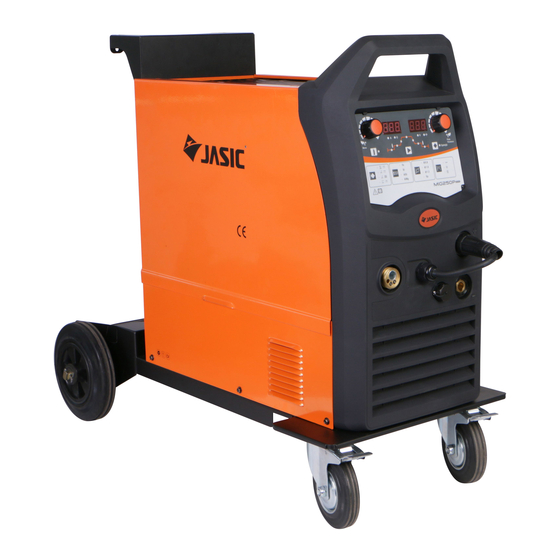
Page 6: Product Overview
·When trouble strikes in installation and operation, please inspect according to related contents in this manual. ·If you still cannot understand fully, or you still cannot solve the problem, please contact the dealer or the service center of JASIC to obtain professional support. 2. PRODUCT OVERVIEW 2.1. -
Page 7: Schematic Block Diagram
2.2.2. Unique control circuit of welding dynamic characteristic, stable welding arc, excellent spot welding, less spatter, nice shape, high welding efficiency. 2.2.3. Molten globule can be removed after welding. With high no-load voltage and slow wire feeding on striking arc, arc striking success rate can be increased. 2.3. -
Page 8: Main Welder Technical Parameters
4. MAIN WELDER TECHNICAL PARAMETERS Model MIG250P(N24901) Input power AC230V single-phase ±15% 50/60Hz Input Rated input capacity 9.13KVA Power factor 0.76 Rated no-load voltage MMA 250A/30V Rated maximum output Lift TIG 250/20V MIG 250A/26.5V Rated duty cycle 40%@AC230V Single-phase Output Welding voltage 13.5V~36V@AC230V Single-phase... -
Page 9: External Characteristic Curve
5. EXTERNAL CHARACTERISTIC CURVE Welding Welding voltage voltage Welding current I/A Welding current I/A External characteristic for MMA External characteristic for MIG/MAG... -
Page 10: Panel Structure And Description
6. PANEL STRUCTURE AND DESCRIPTION 6.1. Panel structure Component Component function name description Display welding current and Segment display welding function Welding function selection Adjusting knob welding parameters setting check Welder gas check button Welding mode MMA, TIG, MIG and pulse button MIG selection Carbon steel/stainless steel/... - Page 11 Component Component function name Power switch Switch power on and off Power cord Connected to external junction box Heater power Connected to heating socket plug of gas meter Gas valve To control gas input Heat dissipation for welder inside Picture 2 Back panel 6.2.
- Page 12 Picture 1-4 Welding wire diameter selecting Picture 1-3 Welding operation selecting zone zone Gas indicator and selection button are included. Welding wire indicator and selection button are Operation methods including spot, 2T and 4T can included. be selected by pressing the button. Corresponding Φ...
- Page 13 Picture 1-6 Current parameters selecting zone Picture 1-7 Voltage parameters selecting zone There current parameters display There voltage parameters display indicator. Current parameters including current (A), indicator. System information and actual welding wire feed speed (m/min) and secondary menu can voltage can be displayed.
-
Page 14: Mig Installtion, Debugging And Operation
6.2.2. Description of welding function and secondary menu 6.2.2.1. MMA mode 1)VRD is on or off by welding operation button corresponding to VRD indicator (VRD is off by default); 2)Secondary menu includes hot start current and arc-force current; It indicates 123A hot start current It indicates 123A arc-force current 6.2.2.2. - Page 15 Diagram: Distribution box connection (for reference) 1 Power switch of distribution box 2 Fuse of 60A or more. 3 Welder cable: Single-phase 230V, copper cable of or more is adopted. 4 Olivine ground wire (connected to GND! instead of null line), copper cable of 4 or more is adopted;...
- Page 16 Distribution box Gas cylinder Cable Torch Earth clamp Weldment 7.2.1. After installation is finished without problems, welder can work when breaker on the back panel is turned on. On-demand fan can work automatically when welding begins or temperature is too high; fan stops working after 30S when there is no current and inverter temperature is lower than 40℃.
- Page 17 speed. Under pulse MIG, welding voltage and pulse parameters can be also automatically selected by adjusting wire feed speed. “Inductance” button on the panel is adjusted to realize soft or hard welding arc characteristic; when it 7.2.4. is rotated anticlockwise, arc becomes hard with low inductance and explosive arc; when it is rotated clockwise, arc becomes soft with high inductance and less spatter.
- Page 18 焊枪开关 Torch trigger Pre-flow 提前送气 空载电压 防粘时间 No-load voltage Anti-stick time 送 气 Gas supply 滞后送气时间 Post-flow time 输出端子间电压 Voltage between output terminals 送 丝 慢送丝 Wire feeding Welding current 焊接电流 Slow wire feeding Crater current 收弧电流 焊接电流 Welding current 焊接中...
- Page 19 40~200 60~100 70~250 80~120 7.4.2. Welding speed selection Welding quality and productivity are main consideration. If welding speed is too fast with poor protective effect which accelerates cooling speed, welding toughness is lowered which is not good for weld shaping; if welding speed is too slow, it is easy to burn through weldment that results in large welding bead.
- Page 20 Welding Board Welding Welding Welding wire Gas flow Number of thickness current voltage speed (L/min) g(mm) diameter layers (A) (V) (cm/min) t(mm) φ(mm) 60~70 17~18 45~55 70~90 18~19 45~55 80~90 18~19 45~55 8~10 45~55 90~110 19~20 8~10 40~55 8~10 0~0.5 80~90 18~19 50~55...
- Page 21 Board Dimension of Welding wire Welding Welding Welding Gas flow thickness fillet weld diameter current voltage speed (L/min) φ(mm) (A) (V) (cm/min) I(mm) t(mm) 2.5~3.0 80~90 19~20 50~60 5~8 2.5~3.0 50~60 90~110 20~21 5~8 3.0~3.5 50~60 5~8 90~100 19~20 2.5~3.0 50~60 8~10 100~110...
- Page 22 7.5.1.4. Stitch welding parameters Board Welding wire Welding Welding Welding Welding Gas flow thickness diameter current voltage speed (L/min) position φ(mm) (A) (V) (cm/min) t(mm) 45~55 70~90 18~19 80~90 18~19 45~55 8~10 A or B 90~110 19~20 45~55 8~10 8~10 80~90 18~19 45~50...
-
Page 23: Mma Installation, Debugging And Operation
8. MMA INSTALLATION, DEBUGGING AND OPERATION Attention: Please install and debug according to following steps! Electrical connection cannot be conducted until distribution box is turned off. Due to IP21S protection class, this machine should not be operated in the rain. Please refer to No.7 “connection of distribution box”. - Page 24 Distribution box Cable Earth clamp Electrode holder Weldment Note: Above is DCRP. Please exchange quick plug of electrode holder and that of earth clamp to plug into the output quick socket of the welder.
- Page 25 8.3. Operation: 8.3.1. After installation, breaker on back panel is turned on to activate the welder. Panel first displays version number of the machine and then current setting value which varies between minimum and maximum by adjusting welding current knob. 8.3.2.
-
Page 26: Description Of Fault Alarm And Fault Code On Front Panel
9. DESCRIPTION OF FAULT ALARM AND FAULT CODE ON FRONT PANEL 9.1. Fault indicator Fault indicator is on and segment display shows fault code with flicker under abnormal circumstance. 9.2. Description of fault code Fault code table Fault code Fault name Description Over-current Unacceptable welder current or low driving voltage... -
Page 27: Repair And Maintenance
original gas meter. If output current of heater is too high caused by unsuitable gas meter, 5A fuse of heater on median septum may be burnt. 10.5. Toppling prevention Prevent welding source from being toppled if it is put on slope. 11. -
Page 28: Failure And Maintenance
FAILURE AND MAINTENANCE Safety warning: T he following operation requires sufficient professional knowledge on electric aspect and comprehensive safety knowledge. Operators should be holders of valid qualification certificates which can prove their skills and knowledge. Make sure the input cable of the machine is disconnected from the electricity utility before uncovering the welding machine. -
Page 29: Feeder
There is open circuit on the fuse of heating source; rated current Electrode holder is hot electrode holder is lower than Replace it with one of bigger rated current; its actual working current; Please contact with Jasic maintenance Other failure personnel. - Page 30 MAIN CIRCUIT SCHEMATIC DIAGRAM AND WIRING DIAGRAM FOR CONTROL WIRE OF WIRE FEEDER This product is being improved, thus other parts may be different except for function and operation. Your understanding would be greatly appreciated.