
Related Manuals for Jasic MIG160PFC


Summary of Contents for Jasic MIG160PFC
- Page 1 MIG160PFC/MIG160 MIG200PFC/MIG200 MIG250PFC/MIG250 IGBT INVERTER WELDER Copyright©2022 Shenzhen JASIC Technology Co., Ltd.
- Page 2 2. JASIC reserves the right to change the manual at any time without prior notice. 3. Though contents in this manual have been carefully checked, there might be inaccuracies. Please contact us in case of inaccuracy.
-
Page 3: Table Of Contents
Contents 1. Safety precautions ......................6 1.1. General safety ........................ 6 1.2. Other precautions ......................9 2. Description of symbols ..................... 10 3. Product overview ......................12 4. Technical parameters ....................... 14 5. Installation ........................17 5.1. External interface description ..................18 5.2. - Page 4 For your safety, please read this manual carefully before installing and operating this JASIC equipment. Pay extra attention to all content marked with " ". All operations must be carried out by professional, suitably qualified persons! Page 4...
-
Page 6: Safety Precautions
1. Safety precautions 1.1. General safety SAFETY INSTRUCTION These general safety norms cover both arc welding machines and plasma cutting machines unless otherwise noted. It is important that users of this equipment protect yourselves and others from harm or even death. - Page 7 Arc rays——May injure the eyes and burn the skin. The arc rays from all processes produce intense, visible and invisible (ultraviolet and infrared) rays that can burn eyes and skin. ·Wear an approved welding helmet fitted with an appropriate shade of filter lens to protect your face and eyes when working or watching.
- Page 8 If you still do not fully understand or cannot solve the problem after reading the instructions in this manual, you should contact the supplier or JASIC's service center immediately for professional help.
-
Page 9: Other Precautions
1.2. Other precautions Warning! Location The machine should be located in a suitable position and environment. Care should be taken to avoid moisture, dust, steam, oil or corrosive gases. Place on a secure level surface and ensure that there is adequate clearance around the machine to ensure natural airflow. -
Page 10: Description Of Symbols
2. Description of symbols Warning! Read the Manual Electric shock risk warning WEEE tag Current unit "A" Wire feed speed unit "m/min" Thickness of welding base metal "mm" Voltage unit "V" Inductance of MIG/arc force of MMA MIG burn back time unit "ms" Overheat protection indicator Overcurrent protection indicator VRD function indicator... - Page 11 Welding wire diameter MIG/Lift TIG 2T operation MIG/Lift TIG 4T operation MIG push torch MIG spool torch Other function switching Remote controller MIG synergic function Inching wire feeding function Gas check function Page 11...
-
Page 12: Product Overview
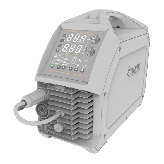
3. Product overview MIG160/MIG200 series MIG250 series This series are digital multi-process inverter DC MIG welders featuring advanced technology with excellent performance. They can be used to weld carbon steel, low-alloy steel, aluminum magnesium alloy and stainless steel, etc. The MIG mode of the welder features preset wire feed speed and welding voltage. - Page 13 accurate. ◆ Anti-stick function: Prevents the welding electrode from sticking to the work piece during welding. ◆ MMA hot start function: Makes MMA arc ignition easier and more reliable. ◆ Lift TIG is controlled by the welding torch. ◆ On-demand fan: Prolongs the life span of fan and reduces accumulation of dust inside the machine.
-
Page 14: Technical Parameters
4. Technical parameters Item Unit MIG160/MIG200/MIG250 Parameters Model MIG250 MIG200 MIG160 Input voltage AC230V±15% AC230V±15% AC230V±15% Input frequency 50/60 50/60 50/60 46.3@MIG 46@MIG 46@MIG Rated input current 33.5@TIG 32@TIG 26@TIG (AC230V) 41.3@MMA 36@MMA 29@MMA 10.51@MIG 8.85@MIG 7.28@MIG Rated input power 9.08@TIG 7.53@TIG 5.98@TIG... - Page 15 19.7@ standard Idle state power <50 <50 <50 Characteristics CC/CV CC/CV CC/CV Pollution level Grade 3 Grade 3 Grade 3 Item Unit MIG160PFC/MIG200PFC/MIG250PFC Parameters Model MIG250PFC MIG200PFC MIG160PFC Input voltage AC230V±15% AC230V±15% AC230V±15% Input frequency 50/60 50/60 50/60 43.7@MIG 38.3@MIG...
- Page 16 Output voltage range 11~30@230V 11~28@230V 11~26@230V (MIG) 11~25@115V 11~24@115V 11~22@115V Wire feed speed range 2~18@230V 2~15@230V 2~14@230V m/min (MIG) 2~13@115V 2~13@115V 2~11@115V Output current range 30~250@230V 30~200@230V 30~160@230V (MIG) 30~160@115V 30~140@115V 30~120@115V Output current range 5~250@230V 5~200@230V 5~160@230V (TIG) 5~160@115V 5~140@115V 5~100@115V Output current range...
-
Page 17: Installation
32.8@ plus 21.8@ plus 21.8@ plus Overall total weight 31.2@ standard 21@ standard 20.8@ standard Idle state power <50 <50 <50 Characteristics CC/CV CC/CV CC/CV Pollution level Grade 3 Grade 3 Grade 3 5. Installation Warning! All connections shall be made with the power supply is turned off. Warning! Electric shock may cause death;... -
Page 18: External Interface Description
5.1. External interface description MIG160/MIG160PFC/MIG200/MIG200PFC series (Front panel view) (Rear panel view) a. Power switch b. Input power cord c. Inlet nozzle of gas valve d. Positive polarity e. Negative polarity f. Central socket g. Polarity changeover connector h. 9-pin aviation socket (optional) i. - Page 19 MIG250/MIG250PFC series (Front panel view) (Rear panel view) a. Power switch b. Input power cord c. Inlet nozzle of gas valve d. Positive polarity e. Negative polarity f. Central socket g. Polarity changeover connector h. 9-pin aviation socket (optional) i. Wireless receiver module (optional) Page 19...
-
Page 20: Power Installation
5.2. Power installation Warning! The electrical connection of equipment shall be carried out by suitably qualified personnel. Warning! All connections shall be made after the power supply is off. Warning! Incorrect voltage may damage the equipment. 1) Ensure the input voltage value is within the specified input voltage range. 2) Ensure that the power switch is turned off. -
Page 21: Mig Welding Torch And Earth Cable Connection
5.3. MIG welding torch and earth cable connection 5.3.1 Digital/analog MIG welding torch Junction box Grounding Power cord (Wiring diagram of MIG: DCEP) Pay attention to the polarity of wiring before MIG. Generally, there are two connection methods of DC welder: DCEN and DCEP. DCEN: The workpiece is connected to the positive polarity, and the polarity changeover connector is connected to the negative polarity;... - Page 22 5.3.2 Spool torch Junction box Grounding Power cord (Wiring diagram of spool torch: DCEP) Pay attention to the polarity of wiring before MIG. See section 5.3.1 for details. Take DCEP as an example: 1) Ensure that the power switch of the welder itself is turned off. 2) Insert the torch plug into the central socket on the front panel of the welder and tighten it clockwise.
-
Page 23: Mma Electrode Holder And Earth Cable Connection
5.4. MMA electrode holder and earth cable connection Junction box Grounding Power cord (Wiring diagram of MMA: DCEP) Pay attention to the polarity of the wiring before MMA. Generally, there are two connection methods of DC welding: DCEN and DCEP. DCEN: The electrode holder is connected to the negative polarity, and the workpiece is connected to the positive polarity;... -
Page 24: Lift Tig Welding Torch And Earth Cable Connection
5.5. Lift TIG welding torch and earth cable connection Junction box Grounding Power cord (Wiring diagram of Lift TIG: DCEN) 1) Ensure that the power switch is turned off. 2) Insert the torch plug into the central socket on the front panel of the welder and tighten it clockwise. -
Page 25: Wired Handheld Remote Controller / Foot Pedal Controller Connection (Optional)
5.6. Wired handheld remote controller / foot pedal controller connection (optional) (Wiring diagram of wired remote controller) Insert the 9-pin aviation plug of the handheld remote controller/foot pedal controller directly into the corresponding 9-pin aviation socket of the machine. Note! Please check with the seller whether the hardware and software versions of the machine support wired handheld remote controller before installation. -
Page 26: Control Panel
6. Control panel 6.1. Overview a.Parameter display A b.Parameter display B c.Welding mode selector d.Welding type selector e.Welding wire diameter selector f.MIG/Lift TIG operation mode selector g.Push/spool torch selector h.Enable remote control i.Synergic j.Inching feeding k.Gas check l.Parameter adjustment knob A m.Parameter adjustment knob B n.Alarm/protection indicator... - Page 27 a. Parameter display A Parameter display A is used to display the current, wire feeding speed, and plate thickness parameters and error code. 1) When not welding, the preset value of current parameter will be displayed. If no operation is performed for a long time, the default parameters are displayed. 2) When welding, the actual output current value is displayed.
- Page 28 d. MIG type selection 1) In MIG mode, press the welding type selection keys to switch the welding type. 2) If the corresponding welding type indicator is on, it indicates that the welding type has been selected. e. Selection of MIG welding wire diameter selection 1) In MIG mode, press the corresponding function switching key to select an optional welding wire diameter for the welding type.
- Page 29 spool torch. 1) If the indicator is on, it indicates that the MIG is in push torch state. 2) If the indicator is on, it indicates that the MIG is in spool torch state. h. Selection of remote control function Wired remote controller 1) Enter the Welding Engineer Mode (see section 6.4 for details), set the "F09"...
- Page 30 remote controller types. See the description of remote controller for specific operation. i. MIG synergic function switching 1) In MIG mode, press the "Synergic" function key to enable or disable the function. 2) If the indicator is on, it indicates that the "Synergic" function is enabled. If it is off, it indicates that the function is disabled.
- Page 31 3) Rotate the adjustment knob to adjust the parameters. 4) Rotating the adjusting knob clockwise increases the parameter value, and rotating it counterclockwise decreases the value. 5) When the adjustment knob is rotated, the adjusted parameter is displayed in the parameter display area.
-
Page 32: Barcode Display
6.2. Barcode display 1) Before welding, press and hold the "Welding Mode Selection" key and "Parameter Adjustment Knob A" for 3s at the same time, and the machine barcode will be displayed. 2) Press any key or wait for 20s to exit the barcode display. 3) The barcode is displayed in nine groups of data in the "Parameter Display A"... - Page 33 Restored Restored Restored Parameter Parameter Parameter Parameter Remark Option Name Value Value Value MIG160 series MIG200 series MIG250 series Burn back time 0.2S 0.2S 0.2S Burn back voltage Inductance Pre-flow time 0.1S 0.1S 0.1S Post-flow time 0.5S 0.5S 0.5S parameters Welding voltage 19.0V 19.0V...
-
Page 34: Welding Engineer Mode Functions
6.4. Welding engineer mode functions The Welding Engineer Mode function allows users to set/modify the default parameters/functions as follows: 1) Press and hold "Parameter Adjustment Knob A" for 5s in startup state. 2) After pressing and holding the "Parameter Adjustment Knob" for 2s, the machine will count down from 3s;... - Page 35 Lift TIG: 5 "Welding Mode" when in Welding Engineer Mode . 1) If the "Welding Mode" is MIG, set the MIG post-flow time, with range 0-5.0, accuracy of 0.5, and unit of seconds. 2) If the "Welding Mode" is Lift TIG, set the Lift TIG post-flow time, with range 0-10.0, accuracy of 0.5, and unit of seconds.
-
Page 36: Welding Function Operation
7. Welding function operation Warning! Before turning on the power supply make sure that the equipment is disconnected to the output. Otherwise, an unexpected arc may be started when the power is turned on. This can cause damage to the work piece and to personnel. - Page 37 7.1.2 Select MIG mode (MIG mode: Synergic enabled) 1) Press the "Welding Mode Selection" key to select MIG mode. 2) Use the corresponding function switching key to select the welding type, wire diameter, operation method and welding torch type. 3) Enable/disable the "Synergic" function. 4) Use "Parameter Adjustment Knob A/B"...
- Page 38 (ms) Parameter options or range (Input 115V Parameter MIG250P MIG200P MIG160P Name MIG250 MIG200 MIG160 Wire feed 2~13 2~13 2~11 speed (m/min) Welding 11~25 11~24 11~22 voltage (V) Inductance -10~10 -10~10 -10~10 Burn back time 0~800 0~800 0~800 (ms) 7.1.4 Set welding parameters with Synergic enabled (Setting welding current) (Setting wire feed speed) (Setting plate thickness)
- Page 39 7.1.5 Use of digital torch or spool torch (optional) In addition to the common push torch, these inverter welders also support digital MIG torch and spool torch. The parameters are adjusted through the keys on the digital torch or the adjustment knob on the spool torch.
- Page 40 (Select spool torch) 1) After connecting the spool torch with the welder, select the "Spool Torch" mode of the welding torch type. 2) When the remote control function is enabled, the "Wire Feed Speed" is adjusted by the potentiometer of spool torch. 3) When the remote control function is disabled, the "Wire Feed Speed"...
- Page 41 Welding sequence of MIG 2T/4T operation Mode Schematic diagram Pre-flow Torch trigger No-load voltage Gas supply Anti-stick time Post-flow supply time Output voltage Wire feed Slow wire feed Welding current Welding Torch trigger Pre-flow No-load voltage Gas supply Anti-stick time Post-flow supply time Output voltage Wire feed...
-
Page 42: Mma Operation
7.1.7 Turn off the power supply after welding The power switch is located on the rear panel of the machine and set it to the "OFF" position. After a time delay, the panel indicator is off and the welder stops working. 7.2. - Page 43 Electrode Electrode Welding diameter (mm) diameter (mm) current (A) 25~40 40~65 2.0~3.2 50~80 100~130 100~130 3.2~4.0 160~210 200~270 ≥5 220~300 NOTE! The operator should set the functions that meet the welding requirements. If the selections are incorrect, this may lead to problems such as an unstable arc, spatter, or sticking of the electrode to the work piece.
-
Page 44: Lift Tig Operation
When the short circuit is cleared, the welding current will automatically return to the set current. 7.2.5 Turn off the power supply after welding (Same as section 7.1.7) The power switch is located on the rear panel of the machine and set it to the "OFF" position. After a time delay, the panel indicator is off and the welder stops working. - Page 45 7.3.4 Start welding Description of MIG 2T/4T operation 2T operation mode 4T operation mode Step 1: Press the torch trigger to start Step 1: Press the torch trigger for the first time to welding. start welding. Step 2: Release the trigger to stop Step 2: Release the trigger for the first time to welding.
-
Page 46: Standby
7.4. Standby (Standby state interface) 1) Enter standby state: In both MIG and Lift TIG modes, the machine will enter standby state and close the display window in the operation panel if there are no welding or panel operations for a long time. The default standby response time is 10 minutes. 2) Exit standby state: In standby state, any operation on the welder will cause it to exit standby state, including welding, key/knob operation, pressing the torch trigger, or operating the paired and valid remote controller, etc. -
Page 47: Maintenance
8. Maintenance Warning! The following operation requires sufficient professional knowledge on electric aspects and comprehensive safety knowledge. Make sure the input cable of the machine is disconnected from the electricity supply and wait for 5 minutes before removing the machine covers. Please note: The following should only be carried out by an authorised electrical technician. -
Page 48: Troubleshooting
9. Troubleshooting Warning! Before machines are dispatched from the factory, they have already been checked thoroughly. The machine should not be tampered with or altered. Maintenance must be carried out carefully. If any wire becomes loose or is misplaced, it maybe potentially dangerous to user! Only professional maintenance personnel should repair the machine! Ensure the power is disconnected before working on the machine. - Page 49 · The welding wire is of poor quality Please contact the maintenance Other faults personnel of JASIC Technology Co. Ltd Elimination of general problems in MMA Symptom Reasons Troubleshooting When the temperature is too low, leave the machine work for a while.
- Page 50 · Use different power cords to connect welding grid is poor. equipment that could seriously interfere process Serious interference with welder. from other electrical equipment. Please contact the maintenance Other faults personnel of JASIC Technology Co. Ltd Page 50...
-
Page 51: Alarm And Solutions
9.2. Alarm and solutions Error Possible Category Countermeasure cause code Continuously Restart the welder. If it is still in overcurrent output the protection, contact the after-sales department of the Overcurrent maximum company. capacity protection current of welder Turn it off and on again. If this the alarm cannot be eliminated and the grid voltage remains too low, Input network Undervoltage... -
Page 52: Common Mig Malfunction
9.3. Common MIG malfunction When the welding conditions do not meet the requirements, the phenomena described in the following table will occur: Table 9.3 Common MIG malfunction Unsuitable Unsuitable Welding Result Result Welding Condition Condition The arc is unstable, The arc is too long and the resulting in welding fusion spatter increases. -
Page 53: Packaging, Transportation, Storage And Waste Disposal
10. Packaging, transportation, storage and waste disposal 10.1. Transportation requirements In the process of handling the equipment, it should be handled with care, and should not be dropped or severely impacted. Avoid moisture and rain during transportation. 10.2. Storage conditions Storage temperature:-25 ℃... -
Page 54: After-Sales Service
To repair or replace the device, contact a local dealer. Please use accessories or consumables provided by Shenzhen JASIC Technology Co., Ltd. The warranty of this machine is subject to the date of sale on the warranty card or sales contract. -
Page 55: Appendixes
Appendixes Appendix 1: Wiring diagram Wiring diagram 1 - MIG160/MIG200 Note! Some models do not support PCB2 and 9-pin aviation socket. Please confirm with the seller whether the machine supports this function before purchasing. Page 55... - Page 56 Wiring diagram 2 - MIG160PFC/MIG200PFC Note! Some models do not support PCB2 and 9-pin aviation socket. Please confirm with the seller whether the machine supports this function before purchasing. Page 56...
- Page 57 Wiring diagram 3 - MIG250 Note! Some models do not support PCB2 and 9-pin aviation socket. Please confirm with the seller whether the machine supports this function before purchasing. Page 57...
- Page 58 Wiring diagram 4 - MIG250PFC Note! Some models do not support PCB2 and 9-pin aviation socket. Please confirm with the seller whether the machine supports this function before purchasing. Page 58...
-
Page 59: Appendix 2: List Of Common Spare Parts
Appendix 2: List of common spare parts List of common spare parts 1 - MIG160/MIG200 Page 59... - Page 60 List of spare parts (Plus) Material Material Name Quantity Name Quantity code code 10021855 Quick socket 51000695 Wire feeder 51000684 Quick coupling 51000824 Central socket 9-pin aviation 51000875 Display panel 51000686 socket and cable 10083484 Knob 51000780 Wire feeder 51001033 51001005 Main board light board...
- Page 61 List of common spare parts 2 - MIG160PFC/MIG200PFC Page 61...
- Page 62 Display 9-pin aviation socket 51000875 51000686 panel and cable 10083484 Knob 51000778 Wire feeder Main 51001033 51001006 light board board@MIG160PFC Main control Main 51001014 51001007 board board@MIG200PFC 51000711 Gas valve 51000706 Thermal resistor 51000471 Power switch 51000691 Hall sensor (Standard)
- Page 63 List of common spare parts 3 - MIG250 Page 63...
- Page 64 List of spare parts (Plus) Material Material Name Quantity SN Name Quantity code code 10084286 Knob switch 10021855 Quick socket Main control Wire feeder light 51001027 51001033 board board 51001816 Fan (small) 51000966 Central socket 51000778 Fan (large) 51000967 Wire feeder 51001003 Main board 51000962...
- Page 65 (Standard) Material Material Name Quantity Name Quantity code code 10084286 Knob switch 10021855 Quick socket Main control Wire feeder light 51002079 51001033 board board 51001816 Fan (small) 51000966 Central socket 51000778 Fan (large) 51000967 Wire feeder 51001003 Main board 51000962 Gas valve IGBT thermal 10084574...
- Page 66 List of common spare parts 4 - MIG250PFC Page 66...
- Page 67 List of spare parts (Plus) Material Material Name Quantity Name Quantity code code 10084286 Knob switch 10021855 Quick socket Main control Wire feeder light 51001022 51001033 board board 51001816 Fan (small) 51000975 Central socket 51000778 Fan (large) 51000974 Wire feeder 51001013 Main board 51000962...
- Page 68 (Standard) Material Material Name Quantity Name Quantity code code 10084286 Knob switch 10021855 Quick socket Main control Wire feeder light 51001812 51001033 board board 51001816 Fan (small) 51000966 Central socket 51000778 Fan (large) 51000967 Wire feeder 51001013 Main board 51000962 Gas valve Secondary 10084574...
-
Page 69: Appendix 3 Packaging And Parts
Appendix 3 Packaging and parts Name Unit Quantity Product certificate Copy Warranty card Copy Desiccant Accessories Welder General packaging Parts of MIG160/MIG160PFC/MIG200/MIG200PFC (plus) Material Classification Name Unit Quantity code Earth clamp 300A-16mm2-KDP70A(3M) 10021496 MIG welding torch MB-15(3M) BINZEL 10019692 Hose clamp... - Page 70 Page 70...
Need help?
Do you have a question about the MIG160PFC and is the answer not in the manual?
Questions and answers