Advertisement
NON MAINTAINED EMERGENCY LUMINAIRES
Operation VOLTAGE
MAXIMUM POWER CONSUMPTION
SUPPLY CURRENT
Prated/Irated
Iemergency
WIRE CROSS SECTION
U-OUT
BATTERY (DJWS12-7.0)
MAX. CHARGING VOLTAGE IN NORMAL CYCLE
MAX. VOLTAGE IN STANDBY OPERATION
MIN. - MAX.CHARGE CURRENT / VOLTAGE RANGE
MIN. - MAX. DISCHARGE CURRENT / VOLTAGE RANGE
BATTERY PROTECTION
Rated CURRENT @12V
OPEN CIRCUIT VOLTAGE
CONTROL GEAR FUSE
CONTROL GEAR MAX. TEMPERATURE
CONTROLGEAR MIN/MAX VOLTAGE LOAD OUTPUT
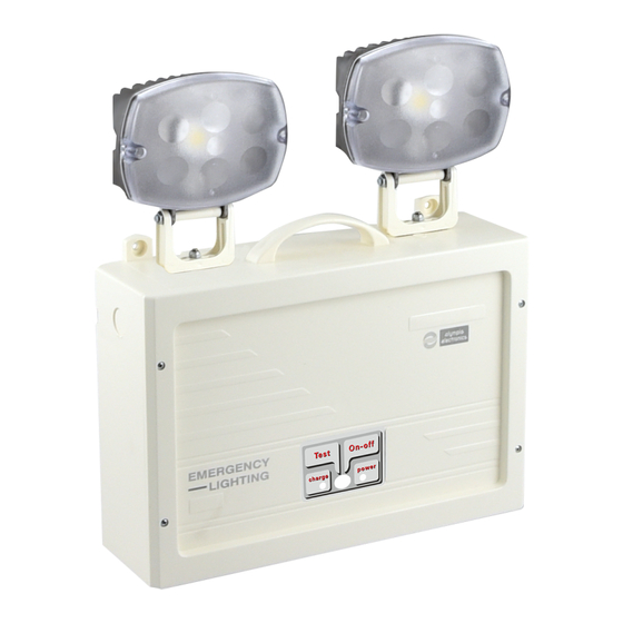
INDICATIONS - CONTROLS
CHARGING TIME
MINIMUM AUTONOMOUS DURATION
LIGHT SOURCE
EMERGENCY ILLUMINATION
DEGREES OF COVER PROTECTION
PRODUCED IN ACCORDANCE WITH
OPERATION TEMPERATURE RANGE
RELATIVE HUMIDITY
CONSTRUCTION MATERIALS
EXTERNAL DIMENSIONS
TYPICAL WEIGHT
GUARANTEE
ELECTRONIC CONTROL GEAR
The lamp controlgear relies upon the luminaire enclosure for protection against accidental contact with live part (7.2 BS EN 61347-2-7)
The controlgear is proof against supply voltage polarity reversal
The controlgear is suitable for LED module only
The controlgear can supply the LED modules only during emergency operation
The controlgear has mains-connected windings of transformer
Manufacturer
Model Number
Voltage Range
Nominal Power
Supply Current
Max Working Voltage for Proper Insulation
LV Supply - Control Conductors Insulation Type
Connections
Temperature (tc)
LED Module Type
NOTE Maintenance of the declared insulation barrier for the luminaire can also be dependent on other external
components/products connected to the same bus. This is the responsibility of the control system designer, not
the luminaire manufacturer.
Page 1 from 3
TECHNICAL CHARACTERISTICS
GRL-21/H/90
Sealed Lead-Acid 12V/7Ah, 0 ~ 40°C
Deep discharge and overcharge protection / the control gear will recharge the battery normally after the test of 22.3
90 min
EN 60598-1, EN 60598-2-22, ΕΝ 55015, ΕΝ 61547, ΕΝ 61000-3-2, ΕΝ 61000-3-3
4100gr
LED MODULE CHARACTERISTICS
Cable connection between main pcb and led module
220-240V AC/50-60Hz
13.3W/14VA
63 mA
21.6W / 1.2A
590mA per Lamp
Power Cables: 0.8-2.5mm
30V
2 x Sealed Lead-Acid 12V/7Ah, 0 ~ 40°C
14.5V
13.8V
230 - 710 mA / 10.5 - 14.5V
1700 - 2300 mA / 13.8 - 10.5
2.15A
23.5V DC
8A/250V FB, 5x20mm
75°C at R11
17 / 23V
Power, Battery Charge / TEST Button
24h
White LEDs
3200lm
IP42
o
5 to 40 C
Up to 95%
Aluminium, ABS/PC, PC
302 x 94 x 350 χιλ.
3 years (1 year for the battery)
Olympia Electronics S.A.
2002163
19-23V
4.9W
590 mA on each lamp
700 V
Basic Insulation
60 °C max. across the board
Built-in
GRL-21/H/180
2
180 min
6300gr.
923021042_09_005
Advertisement
Table of Contents

Related Manuals for olympia electronics GRL-21/H/90


Summary of Contents for olympia electronics GRL-21/H/90
- Page 1 The controlgear is proof against supply voltage polarity reversal The controlgear is suitable for LED module only The controlgear can supply the LED modules only during emergency operation The controlgear has mains-connected windings of transformer LED MODULE CHARACTERISTICS Olympia Electronics S.A. Manufacturer Model Number 2002163 Voltage Range...
- Page 2 Olympia Electronics reserves the right to repair or to replace the returned goods and to or not charge the buyer depending on the reason of defection. Olympia Electronics reserves the right to charge or not the buyer the transportation cost.
- Page 3 INSTALLATION PROCEDURE (For wall mounting only) Mounting holes Fig. 1 Cover retaining screws Power Charge indicator indicator TEST button 1. Use the supplied mounting accessories to mount the device (Fig1). 2. Remove the four cover retaining screws (Fig 1). 3. Install the battery cable connectors to the batteries taking care of the polarity, black cable (-) and red cable (+). 4.
Need help?
Do you have a question about the GRL-21/H/90 and is the answer not in the manual?
Questions and answers