
Related Manuals for Gram bioline BioUltra UL570


Summary of Contents for Gram bioline BioUltra UL570
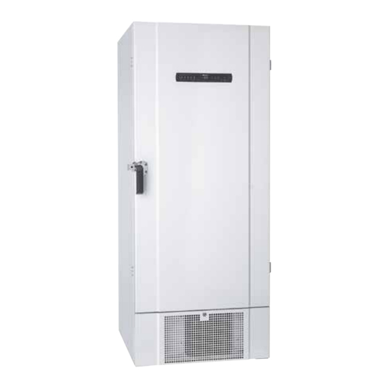
- Page 1 b i o l i n e BioUltra INSTRUCTIONS FOR USE MODEL: UL570 Instructions for use – BioUltra Models: 570 Original Instructions for use Item nr. 765041576 Revision nr. 20230901 English...
-
Page 2: Quick Guide - Bioultra
Quick Guide – BioUltra On/Off Press the button to turn the cabinet on. Press the button for 6 seconds to turn the cabinet off. The software version of the cabinet will be shown when turning the cabinet on, followed by the variant. The cabinet is ready when the temperature is displayed. - Page 3 b i o l i n e Alarms The upper alarm limits, (LHL) alarm is or has been activated Alarm codes The lower alarm limits, (LLL) alarm is or has been activated Acknowledging an acoustic alarm Temperature alarm codes A2 and/or A3: Flashes in the display. Press to acknowledge.
-
Page 4: Table Of Contents
Display sensor ......32 Copyright © 2006- Gram BioLine, a division of Gram Scientific, Denmark. All rights reserved. The content of this publication is owned by Gram BioLine, unless otherwise noted, and is protected by Danish and Manufactured by international copyright laws and provisions. -
Page 5: Safety
Make sure to read the instructions for use through thoroughly before using the cabinet for the first time. In the event of need for product support, do not hesitate to contact us at: support@gram-bioline.com This instructions for use is intended for the following... -
Page 6: Cabinet Components
Cabinet components This part describes the main components pertinent to the user. ATTENTION – In the event of technical difficulties always contact Gram BioLine technical support or a Gram BioLine authorized service partner. - Page 7 Remember to set external alarms (EAL). 12. Pressure equalisation valve Do not use as access port. Keep it as free of ice as possible. ATTENTION – If parts show signs of damage: do not use cabinet and contact Gram Bioline or supplier for further aid.
-
Page 8: Installation
Installation Initial setup This part of the instructions for use describes how to set up the cabinet. I-1*: Due to safety and operating considerations, the cabinet must not be used outdoors. I-2*: The cabinet should be installed in a dry and sufficiently ventilated area. I-3*: To ensure efficient operation, the cabinet should not be installed in direct sunlight or close to heat sources. - Page 9 b i o l i n e This part of the instructions for use describes how to adjust the levelling castors on the cabinet. I-10*: All BioUltra cabinets are equipped with multifunctional levelling castors. These allow for easy positioning, with the added stationary stability of legs once deployed. Turn the dial to either raise or lower the legs.
-
Page 10: Surroundings
Surroundings I-12-13*: The cabinet must always be placed minimum 50 mm from the wall while in use. Allowing warm exhaust from the compressor room to dissipate. And at least a 30 mm between cabinet sides and or/ walls. ≥ 30 mm ≥... - Page 11 b i o l i n e I-14*: Do not cover the holes in the front panel of the cabinet. I-15*: Do not use electrical appliances inside the cabinet. The cabinet is not suited for storing items that emit vapours, as they might corrode the cabinet and its components. All items in the cabinet that are not encapsulated, or wrapped, should be covered to reduce the risk of corrosion of the cabinet and its components.
-
Page 12: Mounting Of Shelves
Mounting of shelves This part of the instructions for use covers mounting and rearranging of the shelving in the cabinet. I-16*: Mount the shelf support clips to the wall rails, using the numbering on the wall rails to determine the right shelf height. Finally placing the shelf on the supports. -
Page 13: Correct Use Of Outer Door Handle
b i o l i n e Correct use of outer door handle This part covers the correct use of the outer door handle. Read the following part thoroughly before using the cabinet. I-17*: It is important for safe operation and performance that the door is closed entirely when items in the cabinet are not being accessed. -
Page 14: Correct Use Of Inner Door Handles
Correct use of inner door handles This part covers the correct use of the inner door handles. Read the following part thoroughly before using the cabinet. The inner doors are designed to operate, close and mount/unmount independently. I-18*: The inner doors are locked when the door lever clicks in place and sits flush up against the inner door. -
Page 15: Voltage-Free Contact
b i o l i n e Voltage-free contact Normally Open (NO) Common This part of the instructions for use covers the voltage-free contact. Common The illustration below shows the three connectors for the relay (used f.ex. in connecting to CTS or other external alarm systems). The three connections, are respectively. -
Page 16: Connection To Power
Connection to power Read the following part thoroughly before connecting the cabinet. Contact a qualified electrician if in doubt. I-19*: When setting up in an ordinary scenario that is not subject to regulations for EN 60079-15 zone 2: The appliance may be connected in accordance with applicable local heavy current regulations. Note that there are special regulations for products that are in accordance with EN 60079-15 zone 2 and EN 60079-14: Explosive atmospheres –... - Page 17 Never use the cabinet if the plug is damaged. The cabinet should be examined by a Gram BioLine service technician in such cases. When setting up in an ordinary scenario that is not subject to regulations for Zone 2: The appliance may be connected in accordance with applicable local heavy current regulations.
-
Page 18: Equipotential Bonding
Equipotential bonding This part of the instructions equipotential bonding For installation in ATEX Cat. 3 Zone 2 areas, it is mandatory to have a equipotential bonding, it is not sufficient to use protective earth through the mains connection. To secure equipotential bonding of the unit – the mounted external bonding conductor must be used in accordance with national installation requirements e.g. -
Page 19: Connection To Water Supply
b i o l i n e Connection to water supply Applicable for water cooled and hybrid cooled (air and water cooled) cabinets. When performing the regular maintenance on the cabinet, please check all connections for the water-cooling system and make sure there are no leaks. Water cooled or hybrid cooled means that a cabinet is connected Connection of the water supply must be done to a water supply whereby the heat generated from the cabinet is... -
Page 20: Start-Up
Start-up The digital display The digital display depicted below, shows the cabinets temperature and indicates if the cabinet is connected to a power source. Key pad On / Off lock Parameter setting Temperature setting Defrost O-1*: On / Off Parameter setting •... -
Page 21: Walkthrough Of Menu
b i o l i n e Walkthrough of menu The menu below gives a quick overview of the parameter settings for the cabinet. User menu Menu Access Local alarm settings [° C] Upper alarm limit. Code for activated alarm [A2] [°... -
Page 22: Error Codes
Error codes The following table covers the different error codes that might occur Display code Explanation: Local upper alarm LHL is or has been activated Local lower alarm LLL is or has been activated External upper alarm EHL is or has been activated External lower alarm ELL is or has been activated Error on the main cabinet sensor. -
Page 23: Examples Of Alarms
b i o l i n e Examples of alarms Acknowledge an acoustic alarm Temperature alarm codes A2 and/or A3: Flashes in the display. Press to acknowledge. The display will continue to flash if the temperature is outside the alarm limits. Latching alarms: A2, A3, A4, A5 Due to the potential implications of alarms, the red alarm triangle icon will turn on along with the corresponding alarm code will flash in the display. -
Page 24: Local Alarms
Local alarms Local high alarm Local low alarm The following part covers the setting of upper and lower temperature alarm limits. O-3*: LHL – Setting the upper alarm limit [° C] Press and hold for more than 3 seconds. “LAL” is shown in display Press to select “LAL”. -
Page 25: Local High Alarm Delay
b i o l i n e b i o l i n e Local high alarm delay Local low alarm delay The following part covers the setting of the delay for the local upper and lower temperature alarm limits. O-5*: LHd –... -
Page 26: Local Acoustic Settings
Local acoustic settings The following part covers the setting of the acoustic local alarms. O-7*: bU – Activation / deactivation of the acoustic local alarms Press and hold for more than 3 seconds. “LAL” is shown in display Press to select “LAL”. “LHL” is now shown in the display Press several times until “bU”... -
Page 27: External Alarms
External alarms b i o l i n e External high alarm External low alarm The following part covers the setting of upper and lower external temperature alarm limits. O-8*: EHL – Setting the external upper alarm limit [° C] Press and hold for more than 3 seconds. -
Page 28: External High Alarm Delay
External high alarm delay External low alarm delay The following parts covers the setting of the delay of the external upper and lower alarms. O-10*: EHd – Setting the delay of the external upper alarm limit [min.] Press and hold for more than 3 seconds. -
Page 29: External Acoustic Settings
b i o l i n e External acoustic settings The following part covers the setting of the acoustic external alarms. O-12*: bU – Activation / deactivation of the acoustic external alarms Press and hold for more than 3 seconds. “LAL” is shown in display Press to proceed to “EAL”... -
Page 30: Parameter Settings
Parameter settings Sensor offset The following part covers the offsetof the A- and E-sensor. Offset of the A-sensor O-13*: The temperature sensors connected to MPC controller can be off-set independently of each other in the parameter cAL. Offset is used in cases where there are deviations in the Press and hold for more than 3 seconds cabinets actual temperature compared to the temperature... -
Page 31: Escorted / Set Alarm Limits
b i o l i n e Escorted / set alarm limits The following part covers the setting of escorted or set alarm limits. ALL – Setting of escorted / set alarm limits Press and hold for more than 3 seconds Press several times until “ALL”... -
Page 32: Display Sensor
Display sensor The following part covers the setting of which sensor to be shown in the display. dPS – Selection of reference sensor for the display Press and hold for more than 3 seconds Press several times until “dPS” is shown in the display Press to select “dPS”... -
Page 33: Regular Maintenance
Regular maintenance b i o l i n e Cleaning Inadequate cleaning can lead to the cabinet not functioning properly or at all. The cabinet must be completely thawed prior to cleaning. The cabinet should be cleaned internally with a mild soap solution (max. 85 °C) at suitable intervals and checked thoroughly before it is put into operation again. -
Page 34: Door Gasket
The door gasket should be cleaned regularly with a mild soap solution and dried off with a dry cloth. If a gasket needs to be replaced, please contact your local Gram BioLine distributor. The illustration below shows the location of the gaskets. -
Page 35: Defrost Inner Doors And Cabinet
b i o l i n e Defrost inner doors and cabinet The following part covers the procedure for manually defrosting inner doors and cabinet. The BioUltra has no automatic defrosting system and requires manual defrosting. In the event of excessive frost and ice build-up, where it hinders performance, general use, and/or item safety, defrosting the chamber and inner doors is needed. -
Page 36: Equalisation Valve
Equalisation valve The equalisation valve may require cleaning depending on use and ambient conditions. Over the duration of some weeks, a small amount of ice can form around the inside of the pressure equalisation valve. If allowed to build up, pressure equalisation will be impeded to the point where the cabinet is not able to equalise through the valve after a door opening. This in turn forces the equalisation to occur over the door gaskets. -
Page 37: General Info
Defective parts must be replaced with original parts from Gram BioLine. Gram BioLine can only guarantee functional and safety requirements on the cabinets, if above mentioned is adhered to. -
Page 38: Type/Number Plate
Type/number plate If refrigeration fails, first look to see whether the cabinet has been unintentionally switched off, or whether a fuse has blown. If the cause of failure cannot be found, contact your supplier quoting Type and S/N. This information can be found on the type/number- plate. -
Page 39: Access Port
b i o l i n e Access port All BioLine cabinets are equipped with an access port on the back of the cabinets, this can be used to easily fit external sensors and the like. The illustration below shows an access port on a BioUltra cabinet. The access ports are constructed in the same fashion, with two conical polystyrene plugs (fitted from the back of the cabinet and the inside of the cabinet). -
Page 40: Boxes And Racks
Boxes and racks This part covers quantity of racks stored in the cabinet. Box size Number of Boxes Number of Racks 2” / 50 mm 24 (4 x 4 racks) 3” / 75 mm 16 (3 x 4 racks) 4” / 100 mm 24 (2 x 4 racks) -
Page 41: Mount / Unmount Door Handle
b i o l i n e Mount / Unmount door handle Mount / Unmount door handle The door handle can easily be unmounted and mounted again. The door handle can easily be unmounted and mounted again. In the case of the handle needing to be taken off, make sure that it is mounted back onto the cabinet prior to starting up again. In the case of the handle needing to be taken off, make sure that it is mounted back onto the cabinet prior to starting up again. -
Page 42: Important
Important IMPORTANT! There may occur sharp edges on the cabinet housing, compressor room, and interior furnishings. Show due diligence when handling the cabinet, neglect of these precautions can lead to injuries. Danger of wedging of body parts in the frame slot between the door and the cabinet, show due diligence when opening and closing the cabinet door. -
Page 43: Disposal
The crossed out wheelie bin symbolizes that waste of this type can not be disposed of with unsorted municipal waste, but must be collected separately. Contact your local Gram BioLine distributor when the cabinet needs to be disposed of. For additional information, see our website:... -
Page 44: Data Sheet
General data: BioUltra UL570 Technical specifications Data Ambient temperature range +10/+30 °C Temperature range -86/-60 °C Control Unit Gram BioLine MPC-46 Alarms Acoustic and visual temperature alarm Alarm ports Voltage free contact (230 VAC/8A) Access port 2 pcs. Ø24 mm Gross volume... - Page 45 b i o l i n e BioUltra UL570H, 50 Hz BioUltra UL570H, 60 Hz Technical Data Technical Data specifications specifications Refrigerant R404A/R508b/R601 Refrigerant R404A/R508b/R601 Refrigerant charge 215/300/30 g Refrigerant charge 425/304/30 g GWP – CO2e R404A/R508b = 844/4019 GWP – CO2e R404A/R508b = 1668/4072 Connection 230 VAC / 50 Hz (16A)
- Page 46 BioUltra UL570G, 50 Hz BioUltra UL570G, 50 Hz – Hybrid Technical Data Technical Data specifications specifications Refrigerant R290/R170/R601 Refrigerant R290/R170 Refrigerant charge 200/105/14 g Refrigerant charge 200/80 g GWP – CO2e GWP – CO2e Connection 230 VAC / 50 Hz (16A) Connection 230 VAC / 50 Hz (16A) SW variant...
- Page 47 b i o l i n e BioUltra UL570H, 50 Hz – Hybrid Technical Data specifications Refrigerant R404A/R508b/R601 Refrigerant charge 215/300/30 g GWP – CO2e Connection 230 VAC / 50 Hz (16A) SW variant Refrigeration capacity 497 Watt at -90°C Energy consumption -80/20* 12.2 kWh/24h Energy consumption –...
-
Page 48: Refrigeration Circuits
Refrigeration circuits UL570H, Air cooled, 50 Hz... -
Page 49: Ul570H, Air Cooled, 60 Hz
b i o l i n e UL570H, Air cooled, 60 Hz UL570G, Air cooled, 50/60 Hz... -
Page 50: Ul570H, Hybrid (Air And Water Cooled)
UL570H, Hybrid (Air and Water cooled) -
Page 51: Ul570G, Air Cooled
b i o l i n e UL570G, Air cooled... -
Page 52: Ul570G, Hybrid (Air And Water Cooled)
UL570G, Hybrid (Air and Water cooled) -
Page 53: Wiring Diagram
Wiring diagram b i o l i n e UL570... -
Page 54: Declaration Of Conformity
Declaration of conformity English EC Declaration of Conformity We, Gram Scientific ApS declare under sole responsibility that the following products: Range: BioUltra Model: UL570 Rerigerant: HC: R290 & R170 (R601 as additive) HFC: R404A & R508B (R601 as additive) Product description:... - Page 55 b i o l i n e...
-
Page 56: Iq & Oq
IQ / OQ Customer: procedures can vary depending on application and items stored in the Gram BioLine cabinet. Deviations from the specifications dictated in the PQ are to be Location of installation: reported in the deviation report. - Page 57 b i o l i n e Instructions on use to starting the cabinet: 1. Training of the responsible party Date: 2. Operational test of the cabinet Date: 3. Responsible party Tel: Instructions to users: The responsible party is trained in use of the cabinet in reference to the user manual General use of cabinet Objections to the mentioned: Service &...
- Page 58 Installation Qualification – IQ Comply Description of installation Reference Attachment Notes in manual Ensure the cabinet is installed indoors. page 8 Ensure the cabinet is installed in a page 8 dry and sufficiently ventilated area. Ensure the cabinet is not in direct contact with sunlight or other heat page 8 sources.
- Page 59 b i o l i n e Installation Qualification – IQ Comply Description of installation Reference Attachment Notes in manual Ensure that the inner doors can I-18 operate in accordance with the page 14 instructions. Ensure the correct electrical I-19 connection (compare local values page 16 with type/nr plate)
- Page 60 Operation Qualification – OQ Comply Description of installation Reference in Attachment Notes manual Turn on the cabinet – Display test page 20 (software version and variant). Set/adjust set-point temperature. page 20 Set/adjust LHL – page 24 Upper alarm limit (local). Set/adjust LLL –...
- Page 61 b i o l i n e Deviation Report Deviations to the criteria of acceptance are to be documented in the deviation report. A separate deviation report shall be made for each deviation. Mark the entry with the relevant “-ID” specified in the left column in the test specifications.
- Page 62 Approval of test results – Installation Qualification (IQ) The steps in the Installation Qualification – IQ were completed with positive results The steps in the Installation Qualification – IQ were completed with negative results ID of steps with negative results: Approval of test results –...
- Page 63 b i o l i n e NOTES: Model:...
-
Page 64: Performance Qualification
Performance Qualification Customer: Location of installation: Model: Item number: (manual) The PQ consists of inspections of Person responsible for the cabinet: the correct operation of the cabinet under predefined conditions and Name: ________________________________________________ procedures. Prerequisites for the Date: ________________________________________________ PQ are IQ (Installation Qualification) Signature: ________________________________________________ and OQ (Operation Qualification), these must be concluded... - Page 65 b i o l i n e Name list – Persons involved in the test procedure and subsequent report Date Name Company Signature Model: ________________________ SN: ________________________...
- Page 66 Deviations from the specifications dictated in the PQ, are to be reported in the deviation report. The PQ is concluded if all criteria of acceptance are approved and the possible deviations are rectified or accepted. Measurement – Prerequisites Description Accepted The cabinet must be empty while conducting tests, ie without interior fittings such as drawers, shelves etc.
- Page 67 b i o l i n e Deviations from the specifications dictated in the PQ, are to be reported in the deviation report. The PQ is concluded if all criteria of acceptance are approved and the possible deviations are rectified or accepted.
- Page 68 Deviations from the specifications dictated in the PQ, are to be reported in the deviation report. The PQ is concluded if all criteria of acceptance are approved and the possible deviations are rectified or accepted. Measurement – Temperature stabilization Description Accepted The test is intended to provide substantiation for the temperature stability inside the cabinet during normal operation.
- Page 69 b i o l i n e Deviations from the specifications dictated in the PQ, are to be reported in the deviation report. The PQ is concluded if all criteria of acceptance are approved and the possible deviations are rectified or accepted. Measurement –...
- Page 70 Deviations from the specifications dictated in the PQ, are to be reported in the deviation report. The PQ is concluded if all criteria of acceptance are approved and the possible deviations are rectified or accepted. Measurement – Pull-down Description Accepted P-11 The test is intended to provide substantiation for the time it takes for the inside of the cabinet to reach the setpoint temperature specified in P-5.
- Page 71 b i o l i n e Deviations from the specifications dictated in the PQ, are to be reported in the deviation report. The PQ is concluded if all criteria of acceptance are approved and the possible deviations are rectified or accepted.
- Page 72 Deviation Report Deviations to the criteria of acceptance are to be documented in the deviation report. A separate deviation report shall be made for each deviation. Mark the entry with the relevant “P-ID” specified in the left column in the test specifications. P-ID: Description of deviation: Extent to which the deviation has been alleviated:...
- Page 73 b i o l i n e Approval of test results – Performance Qualification (PQ) The steps in the Performance Qualification – PQ were completed with positive results The steps in the Performance Qualification – PQ were completed with negative results ID of steps with negative results: Additional notes: Customer / Responsible party:...
- Page 74 NOTES: Model: ________________________ SN: ________________________...
- Page 75 b i o l i n e Appendix: Door opening – Hold-over Model Tolerances Pull-down Hold-over recovery range* time BioUltra UL570 +/- 5K 45 Minutes 300 Minutes -80/-60 °C 150 Minutes * The temperature span between the initial temperature and the end temperature in the hold-over test P-13,14. Name: Signature: Approved...
- Page 76 Gram Scientific ApS Aage Grams Vej 1 · 6500 Vojens · Danmark Tel: +45 73 20 13 00 e-mail: info@gram-bioline.com www.gram-bioline.com...
Need help?
Do you have a question about the bioline BioUltra UL570 and is the answer not in the manual?
Questions and answers